Dell Latitude C840 Service Manual
Dell Latitude C840 Manual
 |
UPC - 609525176179
View all Dell Latitude C840 manuals
Add to My Manuals
Save this manual to your list of manuals |
Dell Latitude C840 manual content summary:
- Dell Latitude C840 | Service Manual - Page 1
Service Manual Dell™ Latitude™ C840 Service Manual Before You Begin Preparing to Work Inside the Computer Recommended Tools Computer Orientation Screw Identification System Components Hard Drive and Fixed Optical Drive Hard Drive Fixed Optical Drive System Upgrades Memory Modules Modem Daughter Card - Dell Latitude C840 | Service Manual - Page 2
You Begin: Dell Latitude C840 Service Manual Back to Contents Page Before You Begin Dell™ Latitude™ C840 Service Manual Preparing to Work Inside the Computer Recommended Tools Computer Orientation Screw Identification Preparing to Work Inside the Computer CAUTION: Only a certified service technician - Dell Latitude C840 | Service Manual - Page 3
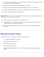
tools: q #1 magnetized Phillips screwdriver q Small flat-blade screwdriver q Microprocessor extractor q Nonmarring plastic scribe q Flash BIOS update floppy disk or CD (provided when needed to upgrade the BIOS) file:///F|/Service%20Manuals/Dell/Latitude/c840/begin.htm (2 of 6) [2/28/2004 8:03:35 AM] - Dell Latitude C840 | Service Manual - Page 4
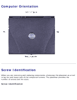
Before You Begin: Dell Latitude C840 Service Manual Computer Orientation Screw Identification When you are removing and replacing components, photocopy the placemat as a tool to lay out and keep track of the component screws. The placemat provides the number of screws and the - Dell Latitude C840 | Service Manual - Page 5
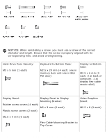
Before You Begin: Dell Latitude C840 Service Manual NOTICE: When reinstalling a screw, you must use a screw of the correct diameter and length. Ensure that the screw is properly aligned with its corresponding hole, and avoid overtightening. Hard-Drive Door Security: M3 x 5 mm (1 each) Keyboard to - Dell Latitude C840 | Service Manual - Page 6
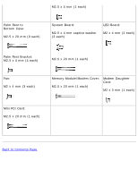
mm (4 each) M2.5 x 20 mm (1 each) Fan: M2 x 4 mm (3 each) Memory Module/Modem Cover: M2.5 x 20 mm (1 each) Modem Daughter Card: M2 x 3 mm (1 each) Mini PCI Card: M2.5 x 20 mm (1 each) Back to Contents Page file:///F|/Service%20Manuals/Dell/Latitude/c840/begin.htm (5 of 6) [2/28/2004 8:03:35 AM - Dell Latitude C840 | Service Manual - Page 7
Before You Begin: Dell Latitude C840 Service Manual file:///F|/Service%20Manuals/Dell/Latitude/c840/begin.htm (6 of 6) [2/28/2004 8:03:35 AM] - Dell Latitude C840 | Service Manual - Page 8
: Dell Latitude C840 Service Manual Back to Contents Page System Components Dell™ Latitude™ C840 Service Manual NOTICE: Unless otherwise noted, each procedure in this document assumes that a part can be replaced by performing the removal procedure in reverse order. file:///F|/Service%20Manuals/Dell - Dell Latitude C840 | Service Manual - Page 9
: Dell Latitude C840 Service Manual 1 display assembly 2 hinge cover 3 microprocessor thermalcooling assembly 4 system board 5 hard drive 6 bottom case 7 main battery 8 device in module bay 9 fixed optical drive 10 palm rest 11 keyboard Back to Contents Page file:///F|/Service%20Manuals/Dell - Dell Latitude C840 | Service Manual - Page 10
Drive and Fixed Optical Drive: Dell Latitude C840 Service Manual Back to Contents Page Hard Drive and Fixed Optical Drive Dell™ Latitude™ C840 Service Manual Hard Drive Fixed Optical Drive NOTICE: Only a certified service technician should perform repairs on your computer. Damage due to servicing - Dell Latitude C840 | Service Manual - Page 11
Drive: Dell Latitude C840 Service Manual 1 bottom of computer 2 M3 x 5-mm screw 3 hard drive door Removing the Hard Drive 1. Follow the instructions in "Preparing to Work Inside the Computer." 2. Remove the M3 x 5-mm screw. 3. Pull the hard drive out. Replacing the Hard Drive 1. Push the hard drive - Dell Latitude C840 | Service Manual - Page 12
Optical Drive: Dell Latitude C840 Service Manual 2. Push down on the drive until it snaps into place. 3. Replace the M3 x 5-mm screw in the hard drive door. Fixed Optical Drive NOTICE: Disconnect the computer and attached devices from the electrical outlet and remove any installed batteries. NOTICE - Dell Latitude C840 | Service Manual - Page 13
Hard Drive and Fixed Optical Drive: Dell Latitude C840 Service Manual Removing the Fixed Optical Drive 1. Follow the instructions in "Preparing to Work Inside the Computer." 2. Loosen the captive screw on the bottom of the computer. 3. Turn the computer over (to keep the captive - Dell Latitude C840 | Service Manual - Page 14
Upgrades: Dell Latitude C840 Service Manual Back to Contents Page System Upgrades Dell™ Latitude™ C840 Service Manual Memory Modules Modem Daughter Card Mini PCI Card Memory Modules NOTICE: Disconnect the computer and any attached devices from electrical outlets and remove any installed batteries - Dell Latitude C840 | Service Manual - Page 15
Upgrades: Dell Latitude C840 Service Manual 1 M2.5 x 20-mm screw 1. Follow the instructions in "Preparing to Work Inside the Computer." 2. Remove the M2.5 x 20-mm screw from the memory module/modem cover. 3. Disengage the metal tabs at the opposite end of the cover. file:///F|/Service%20Manuals/Dell - Dell Latitude C840 | Service Manual - Page 16
System Upgrades: Dell Latitude C840 Service Manual 1 DIMM B 2 memory module sockets (2) 3 DIMM A socket 4 modem daughter card 5 metal tabs (2 per socket) Removing the Memory Modules 1. Remove the memory module/modem cover. 2. To release a memory module from its socket, spread apart the tabs at each - Dell Latitude C840 | Service Manual - Page 17
System Upgrades: Dell Latitude C840 Service Manual Replacing the Memory Modules 1. If you only have one memory module, install it in the socket labeled "DIMM A." Install a second memory module in the socket labeled "DIMM B." NOTE: Memory modules are keyed to fit into their sockets in only one - Dell Latitude C840 | Service Manual - Page 18
cable from the modem daughter card. Replacing the Modem Daughter Card NOTICE: The cable connectors are keyed for correct insertion. Do not force the connections. 1. Connect the modem cable to the modem daughter card. file:///F|/Service%20Manuals/Dell/Latitude/c840/upgrades.htm (5 of 9) [2/28/2004 - Dell Latitude C840 | Service Manual - Page 19
Upgrades: Dell Latitude C840 Service Manual 2. Use the screw and boss holes at opposite corners of the modem daughter card to align the card, and press the card into its connector on the system board. 3. Install the M2 x 3-mm screw that secures the card to the system board. 4. Replace the memory - Dell Latitude C840 | Service Manual - Page 20
System Upgrades: Dell Latitude C840 Service Manual 1 M2.5 x 20-mm screw Removing the Mini PCI Card 1. Follow the instructions in "Preparing to Work Inside the Computer." 2. Remove the M2.5 x 20-mm screw and then remove the Mini PCI card cover. 3. To release the Mini PCI card, spread the metal - Dell Latitude C840 | Service Manual - Page 21
force the connections. 1 internal-antenna cable 2 primary-antenna connector on card 3. Pivot the Mini PCI card down until it clicks into place. 4. Replace the Mini PCI card cover and the M2.5 x 20-mm screw. file:///F|/Service%20Manuals/Dell/Latitude/c840/upgrades.htm (8 of 9) [2/28/2004 8:03:38 AM] - Dell Latitude C840 | Service Manual - Page 22
System Upgrades: Dell Latitude C840 Service Manual Back to Contents Page file:///F|/Service%20Manuals/Dell/Latitude/c840/upgrades.htm (9 of 9) [2/28/2004 8:03:38 AM] - Dell Latitude C840 | Service Manual - Page 23
Keyboard: Dell Latitude C840 Service Manual Back to Contents Page Keyboard Dell™ Latitude™ C840 Service Manual NOTICE: Disconnect the computer and attached devices from electrical outlets and remove any installed batteries. NOTICE: To avoid ESD, ground yourself by using a wrist grounding strap or by - Dell Latitude C840 | Service Manual - Page 24
Keyboard: Dell Latitude C840 Service Manual 1 M2.5 x 20-mm screws (4) Removing the Keyboard 1. Follow the instructions in "Preparing to consuming to replace. 4. Use a nonmarring plastic scribe under the blank key to pry up the keyboard. file:///F|/Service%20Manuals/Dell/Latitude/c840/keyboard.htm - Dell Latitude C840 | Service Manual - Page 25
Keyboard: Dell Latitude C840 Service Manual 1 blank key 2 keyboard 3 right side of computer 5. Lift the right end of the keyboard Pivot the keyboard and balance it upright on the left side of the computer. file:///F|/Service%20Manuals/Dell/Latitude/c840/keyboard.htm (3 of 5) [2/28/2004 8:03:39 AM] - Dell Latitude C840 | Service Manual - Page 26
Keyboard: Dell Latitude C840 Service Manual 1 keyboard cable 2 keyboard interface connector 3 system board 7. Disconnect the keyboard cable and lay the keyboard aside. Replacing the Keyboard 1. While bracing the keyboard upright on its left end, connect the keyboard cable to the keyboard interface - Dell Latitude C840 | Service Manual - Page 27
Keyboard: Dell Latitude C840 Service Manual NOTICE: Position the keyboard/track-stick flex cable so that it is not pinched when you replace the keyboard in the bottom case. 2. Insert the metal tabs at the left end of the keyboard under the edge of the bottom case, and - Dell Latitude C840 | Service Manual - Page 28
Service Manual Back to Contents Page Display Dell™ Latitude™ C840 Service Manual Display Overview Hinge Cover Display Assembly Display Bezel Display Panel Display Latch Display Overview NOTICE: Disconnect the computer and attached devices from electrical outlets and remove any installed batteries - Dell Latitude C840 | Service Manual - Page 29
Display: Dell Latitude C840 Service Manual 1 display 2 hinge cover 3 M2.5 x 6-mm screws (3) 4 bottom case 5 display flex cable file:///F|/Service%20Manuals/Dell/Latitude/c840/display.htm (2 of 10) [2/28/2004 8:03:40 AM] - Dell Latitude C840 | Service Manual - Page 30
Display: Dell Latitude C840 Service Manual Hinge Cover 1 hinge cover 1. Follow the instructions in "Preparing to Work Inside the Computer." 2. Use a nonmarring plastic scribe to loosen the hinge cover at the back and at each side of the - Dell Latitude C840 | Service Manual - Page 31
Display: Dell Latitude C840 Service Manual 1 M2.5 x 6-mm screws (2) 1. Remove the hinge cover. NOTICE: Remove the display flex cable before you remove the display assembly. file:///F|/Service%20Manuals/Dell/Latitude/c840/display.htm (4 of 10) [2/28/2004 8:03:40 AM] - Dell Latitude C840 | Service Manual - Page 32
Display: Dell Latitude C840 Service Manual 1 M2.5 x 6-mm screw 2 strain relief 3 display flex cable 4 pull loop 2. Remove the M2.5 x 6-mm flex-cable strain relief screw, and then use the pull loop to remove the display flex cable from the graphics card. NOTICE: When reconnecting the flex cable, - Dell Latitude C840 | Service Manual - Page 33
Display: Dell Latitude C840 Service Manual file:///F|/Service%20Manuals/Dell/Latitude/c840/display.htm (6 of 10) [2/28/2004 8:03:40 AM] - Dell Latitude C840 | Service Manual - Page 34
Display: Dell Latitude C840 Service Manual 1 M2.5 x 4-mm screws (6) 2 rubber screw covers (4) 3 display bezel 4 plastic tabs (6) 5 scribe to pry out the four rubber screw covers located across the top of the bezel. 2. Remove the four M2.5 x 4-mm screws located across the top of the bezel. 3. Use a - Dell Latitude C840 | Service Manual - Page 35
Display: Dell Latitude C840 Service Manual 2. Detach the display flex cable from the strain relief and the graphics card. 3. Remove the display bezel. 4. Remove the M2.5 x 4-mm screw that secures the plastic flex-cable mounting bracket to the top cover. 5. Remove the six M2 x 3- - Dell Latitude C840 | Service Manual - Page 36
Display: Dell Latitude C840 Service Manual 1 ZIF connector 2 standard connector Replacing the Display Panel NOTE: screw, and reconnect the flex cable to the graphics card. 6. Reinstall the display bezel. Display Latch file:///F|/Service%20Manuals/Dell/Latitude/c840/display.htm (9 of 10) [2/28/2004 - Dell Latitude C840 | Service Manual - Page 37
Display: Dell Latitude C840 Service Manual 1. Remove the hinge cover. 2. Detach the display flex cable from the strain relief and the graphics card. 3. Remove the display bezel. 4. Remove the display panel from the top cover. 5. Remove the display latch by disengaging the latch and captive spring. - Dell Latitude C840 | Service Manual - Page 38
Thermal-Cooling Assembly: Dell Latitude C840 Service Manual Back to Contents Page Microprocessor Thermal-Cooling Assembly Dell™ Latitude™ C840 Service Manual NOTICE: Disconnect the computer and attached devices from electrical outlets and remove any installed batteries. NOTICE: To avoid - Dell Latitude C840 | Service Manual - Page 39
Microprocessor Thermal-Cooling Assembly: Dell Latitude C840 Service Manual 2 microprocessor retaining clip Removing the Microprocessor Thermal-Cooling Assembly 1. Follow the instructions in "Preparing to Work Inside the Computer." 2. Remove the keyboard. 3. Remove the hinge cover. 4. Insert a non- - Dell Latitude C840 | Service Manual - Page 40
Microprocessor Thermal-Cooling Assembly: Dell Latitude C840 Service Manual NOTICE: To ensure maximum cooling for the microprocessor, do not touch 5. Lift out the thermal-cooling assembly. Back to Contents Page file:///F|/Service%20Manuals/Dell/Latitude/c840/thermal.htm (3 of 3) [2/28/2004 8:03:41 AM] - Dell Latitude C840 | Service Manual - Page 41
periodically touching unpainted metal on the computer. Removing the Microprocessor Module 1. Follow the instructions in "Preparing to Work Inside the Computer." 2. Remove the keyboard. 3. Remove the hinge cover. file:///F|/Service%20Manuals/Dell/Latitude/c840/cpu.htm (1 of 5) [2/28/2004 8:03:42 AM] - Dell Latitude C840 | Service Manual - Page 42
Module: Dell Latitude C840 Service Manual NOTICE: a. Loosen the cam screw that secures the microprocessor module. The location of the screw and the rotation direction may vary with the screw and microprocessor. file:///F|/Service%20Manuals/Dell/Latitude/c840/cpu.htm (2 of 5) [2/28/2004 8:03:42 - Dell Latitude C840 | Service Manual - Page 43
Module: Dell Latitude C840 Service Manual 1 cam screw 2 perpendicular screwdriver 3 processor die (do not touch) b. Use the microprocessor extraction tool to remove the microprocessor module. Replacing the Microprocessor Module NOTICE: If you received a flash BIOS update floppy disk or CD with the - Dell Latitude C840 | Service Manual - Page 44
Microprocessor Module: Dell Latitude C840 Service Manual 1. Align the pin-1 triangle on the locked" indicator on the socket. 3. Replace the microprocessor thermal-cooling assembly. Closing the Microprocessor Retaining Clip file:///F|/Service%20Manuals/Dell/Latitude/c840/cpu.htm (4 of 5) [2/28/2004 - Dell Latitude C840 | Service Manual - Page 45
Module: Dell Latitude C840 Service Manual 4. Close the microprocessor retaining clip. 5. To latch the clip, insert a flat-blade scribe into the latch mechanism and pivot the top of the scribe away from the clip. Back to Contents Page file:///F|/Service%20Manuals/Dell/Latitude/c840/cpu.htm - Dell Latitude C840 | Service Manual - Page 46
Video Graphics Board: Dell Latitude C840 Service Manual Back to Contents Page Video Graphics Board Dell™ Latitude™ C840 Service Manual NOTICE: Disconnect the computer and attached devices from electrical outlets and remove any installed batteries. NOTICE: To avoid ESD, ground yourself by using a - Dell Latitude C840 | Service Manual - Page 47
Video Graphics Board: Dell Latitude C840 Service Manual 3. Remove the hinge cover. NOTICE: The video graphics board may have a metallic or cardboard-like EMI shield attached to the top. If present, the EMI shield is removed with the board. Do not reuse the EMI shield on the replacement video board. - Dell Latitude C840 | Service Manual - Page 48
Palm Rest: Dell Latitude C840 Service Manual Back to Contents Page Palm Rest Dell™ Latitude™ C840 Service Manual NOTICE: Disconnect the computer and attached devices from electrical outlets and remove any installed batteries. NOTICE: To avoid ESD, ground yourself by using a wrist grounding strap or - Dell Latitude C840 | Service Manual - Page 49
Rest: Dell Latitude C840 Service Manual NOTICE: The reserve battery provides power to the computer's time RTC and NVRAM when the computer is turned off. Removing the palm rest disconnects the reserve battery and causes the computer to lose the date and time information as well as all user-specified - Dell Latitude C840 | Service Manual - Page 50
Palm Rest: Dell Latitude C840 Service Manual 1 M2.5 x 20-mm screws (9) 8. Turn the computer over. 9. Use the pull loop to disconnect the secure the palm rest to the bottom case. 11. Lift out the palm rest. file:///F|/Service%20Manuals/Dell/Latitude/c840/palmrest.htm (3 of 4) [2/28/2004 8:03:43 AM] - Dell Latitude C840 | Service Manual - Page 51
Palm Rest: Dell Latitude C840 Service Manual Replacing the Palm Rest When replacing the palm rest screws, install the two screws at the back corners of the computer first to help align the palm rest correctly. Back to Contents Page file:///F|/Service%20Manuals/Dell/Latitude/c840/palmrest.htm (4 of - Dell Latitude C840 | Service Manual - Page 52
Reserve Battery: Dell Latitude C840 Service Manual Back to Contents Page Reserve Battery Dell™ Latitude™ C840 Service Manual NOTICE: Disconnect the computer and attached devices from electrical outlets and remove any installed batteries. NOTICE: To avoid ESD, ground yourself by using a wrist - Dell Latitude C840 | Service Manual - Page 53
Reserve Battery: Dell Latitude C840 Service Manual NOTICE: The reserve battery provides power to the computer's RTC and NVRAM when the computer is turned off. Removing the battery causes the computer to lose the date and time information as well as all user-specified parameters in NVRAM. If possible - Dell Latitude C840 | Service Manual - Page 54
Reserve Battery: Dell Latitude C840 Service Manual 1 M2.5 x 4-mm screws (4) 2 palm rest bracket 3 palm-rest flex cable 7. Remove the four M2.5 x 4-mm screws that secure the palm rest bracket. 8. While supporting the palm-rest flex cable, lift out the palm rest bracket and turn it over. 9. Disconnect - Dell Latitude C840 | Service Manual - Page 55
System Board: Dell Latitude C840 Service Manual Back to Contents Page System Board Dell™ Latitude™ C840 Service Manual NOTICE: Disconnect the computer and attached devices from electrical outlets and remove any installed batteries. NOTICE: To avoid ESD, ground yourself by using a wrist grounding - Dell Latitude C840 | Service Manual - Page 56
, you must update the BIOS after replacing the microprocessor module. Removing the System Board 1. Follow the instructions in "Preparing to Work Inside the Computer." 2. Remove the hard drive and the fixed optical drive. 3. Remove any installed Mini PCI Cards. 4. If migrating the memory, remove all - Dell Latitude C840 | Service Manual - Page 57
System Board: Dell Latitude C840 Service Manual 12. If migrating the microprocessor, remove the microprocessor module. 13. Separate the network cable from the system board: a. First remove the network cable cover: Insert a - Dell Latitude C840 | Service Manual - Page 58
System Board: Dell Latitude C840 Service Manual 1 outer corner of upper connector 2 network cable 14. Remove the three M2.5 x 4-mm captive-washer arrow at the far left in the following figure). System Board file:///F|/Service%20Manuals/Dell/Latitude/c840/sysboard.htm (4 of 5) [2/28/2004 8:03:45 AM] - Dell Latitude C840 | Service Manual - Page 59
System Board: Dell Latitude C840 Service Manual Back to Contents Page file:///F|/Service%20Manuals/Dell/Latitude/c840/sysboard.htm (5 of 5) [2/28/2004 8:03:45 AM] - Dell Latitude C840 | Service Manual - Page 60
and Module Bay Latches: Dell Latitude C840 Service Manual Back to Contents Page Battery and Module Bay Latches Dell™ Latitude™ C840 Service Manual NOTICE: Disconnect the computer and attached devices from electrical outlets and remove any installed batteries. NOTICE: To avoid ESD, ground yourself - Dell Latitude C840 | Service Manual - Page 61
and Module Bay Latches: Dell Latitude C840 Service Manual 1 wear ribs (2 on underside) 2 bumps 3 slider 4 spring 5 bottom case 6 latch housing (2) 7 latch buttons (2) 8 location of snap tabs (2) Removing and Replacing the Battery and Module Bay Latches 1. Follow the instructions in "Preparing to - Dell Latitude C840 | Service Manual - Page 62
Battery and Module Bay Latches: Dell Latitude C840 Service Manual b. Ensure that the slider is inserted so that the side with the two moves smoothly and freely when pushed and released. Back to Contents Page file:///F|/Service%20Manuals/Dell/Latitude/c840/baylatch.htm (3 of 3) [2/28/2004 8:03:46 AM] - Dell Latitude C840 | Service Manual - Page 63
touching unpainted metal on the computer. Removing the Battery Charger Board 1. Follow the instructions in "Preparing to Work Inside the Computer." 2. Remove the keyboard. 3. Remove the hinge cover. file:///F|/Service%20Manuals/Dell/Latitude/c840/battch.htm (1 of 2) [2/28/2004 8:03:46 AM - Dell Latitude C840 | Service Manual - Page 64
Battery Charger Board: Dell Latitude C840 Service Manual 4. Remove the display assembly. 5. Remove the palm rest. 6. Remove the video graphics board. 7. Lift the battery charger board out of the system board connector. Replacing the Battery Charger Board Align the screw holes on the battery charger - Dell Latitude C840 | Service Manual - Page 65
LED Board: Dell Latitude C840 Service Manual Back to Contents Page LED Board Dell™ Latitude™ C840 Service Manual NOTICE: Disconnect the computer and attached devices from electrical outlets and remove any installed batteries. NOTICE: To avoid ESD, ground yourself by using a wrist grounding strap or - Dell Latitude C840 | Service Manual - Page 66
LED Board: Dell Latitude C840 Service Manual Removing the LED Board 1. Follow the instructions in "Preparing to Work Inside the Computer." 2. Remove the hinge cover. 3. Remove the two M2 x 4-mm screws. 4. Lift the LED board away from its connector. Replacing the LED Board 1. Align the two screw - Dell Latitude C840 | Service Manual - Page 67
Fan: Dell Latitude C840 Service Manual Back to Contents Page Fan Dell™ Latitude™ C840 Service Manual NOTICE: Disconnect the computer and attached devices from electrical outlets and remove any installed batteries. NOTICE: To avoid ESD, ground yourself by using a wrist grounding strap or by - Dell Latitude C840 | Service Manual - Page 68
Fan: Dell Latitude C840 Service Manual 2. Remove the system board. 3. Remove the three M2 x 4-mm screws from the fan. 4. Disconnect the two fan cables from the system board. 5. Pull the fan away from the back-panel bracket. NOTICE: When reconnecting the fan cables, connect the shorter cable to the - Dell Latitude C840 | Service Manual - Page 69
RJ-11/RJ-45 Module: Dell Latitude C840 Service Manual Back to Contents Page RJ-11/RJ-45 Module Dell™ Latitude™ C840 Service Manual NOTICE: Disconnect the computer and attached devices from electrical outlets and remove any installed batteries. NOTICE: To avoid ESD, ground yourself by using a wrist - Dell Latitude C840 | Service Manual - Page 70
RJ-11/RJ-45 Module: Dell Latitude C840 Service Manual Removing the RJ-11/RJ-45 Module 1. Follow the instructions in "Preparing to Work Inside the Computer." 2. Remove the system board. 3. From outside the bottom case, push in and up on the RJ-11/RJ- - Dell Latitude C840 | Service Manual - Page 71
RJ-11/RJ-45 Module: Dell Latitude C840 Service Manual 1 vertical slot 2 modem cable When replacing the system board, ensure that the network cable is safely above the board and out of the way. Back to Contents Page file:///F|/Service%20Manuals/Dell/Latitude/c840/rj11_45b.htm (3 of 3) [2/28/2004 8:03 - Dell Latitude C840 | Service Manual - Page 72
for I/O Connectors: Dell Latitude C840 Service Manual Back to Contents Page Pin Assignments for I/O Connectors Dell™ Latitude™ C840 Service Manual USB Connector Pin Signal 1 VCC 2 -Data 3 +Data 4 Ground Serial Connector file:///F|/Service%20Manuals/Dell/Latitude/c840/pinouts.htm (1 of - Dell Latitude C840 | Service Manual - Page 73
Pin Assignments for I/O Connectors: Dell Latitude C840 Service Manual Pin Signal Pin 1 DCD 6 2 RXDA 7 3 TXDA 8 4 DTR 9 5 GND Parallel Connector Signal DSR RTS CTS RI Pin Signal Pin Signal file:///F|/Service%20Manuals/Dell/Latitude/c840/pinouts.htm (2 of 10) [2/28/2004 8:03:50 - Dell Latitude C840 | Service Manual - Page 74
Pin Assignments for I/O Connectors: Dell Latitude C840 Service Manual 1 STRB# 2 PD0 3 PD1 4 PD2 5 PD3 6 PD4 7 PD5F 8 PD6F Pin Signal 9 CRT_VCC 10 GND 11 MSEN# 12 DAT_DDC2 13 HSYNC file:///F|/Service%20Manuals/Dell/Latitude/c840/pinouts.htm (3 of 10) [2/28/2004 8:03:50 AM] - Dell Latitude C840 | Service Manual - Page 75
for I/O Connectors: Dell Latitude C840 Service Manual 6 GND 7 GND 8 GND 14 VSYNC 15 CLK_DDC2 PS/2 Connector Pin Signal 1 DAT_KBD 2 DAT_SM1 3 GND 4 PS2VCC 5 CLK_KBD 6 CLK_SM1 S-Video TV-Out Connector file:///F|/Service%20Manuals/Dell/Latitude/c840/pinouts.htm (4 of - Dell Latitude C840 | Service Manual - Page 76
Pin Assignments for I/O Connectors: Dell Latitude C840 Service Manual S-Video Pin Signal 1 GND 2 GND 3 DLUMA-L 4 DCRMA-L Composite Video Pin Signal 5 SPDIF 6 DCMPS-L 7 SPGND Docking Connector file:///F|/Service%20Manuals/Dell/Latitude/c840/pinouts.htm (5 of 10) [2/28/2004 8:03: - Dell Latitude C840 | Service Manual - Page 77
Pin Assignments for I/O Connectors: Dell Latitude C840 Service Manual Pin Signal 1 STRB#/5V 2 PD0 3 PD1 4 PD2 5 PD3 6 PD4 7 PD5 8 PD6 9 PD7 10 GND 11 DOCK_SPKR 12 DOCK_MIC 13 DOCK_LINE 14 DOCK_CDROM 15 GND 16 - Dell Latitude C840 | Service Manual - Page 78
Pin Assignments for I/O Connectors: Dell Latitude C840 Service Manual 18 QPCIEN# 19 S1.6M_EN# 20 DFDD/LPT# 21 GND 22 NC 23 NC # 138 STRK0# 139 SSTEP# 140 SDRV1# 141 GND 142 SMRT1# 143 SWRDATA# 144 SWGATE# file:///F|/Service%20Manuals/Dell/Latitude/c840/pinouts.htm (7 of 10) [2/28/2004 8:03:50 AM] - Dell Latitude C840 | Service Manual - Page 79
Pin Assignments for I/O Connectors: Dell Latitude C840 Service Manual 45 DOCK_+DC_IN 46 DOCK_+DC_IN 47 DOCK_+DC_IN 48 DOCK_+DC_IN 49 GND 50 165 SAD9 166 SAD10 167 SAD11 168 SAD12 169 GND 170 SAD13 171 SAD14 file:///F|/Service%20Manuals/Dell/Latitude/c840/pinouts.htm (8 of 10) [2/28/2004 8:03:50 AM] - Dell Latitude C840 | Service Manual - Page 80
Pin Assignments for I/O Connectors: Dell Latitude C840 Service Manual 72 GND 73 INIT# 74 SLCT_IN# 75 BUSY 76 PE 77 SLCT 78 GND 79 DAT_SMB 80 SAD28 192 SAD29 193 SAD30 194 SAD31 195 GND 196 NC 197 NC 198 NC file:///F|/Service%20Manuals/Dell/Latitude/c840/pinouts.htm (9 of 10) [2/28/2004 8:03:50 AM] - Dell Latitude C840 | Service Manual - Page 81
Pin Assignments for I/O Connectors: Dell Latitude C840 Service Manual 99 NC 100 NC 199 NC 200 GND IEEE 1394 Connector Pin Signal 1 TPB- 2 TPB+ 3 TPA- 4 TPA+ Back to Contents Page file:///F|/Service%20Manuals/Dell/Latitude/c840/pinouts.htm (10 of 10) [2/28/2004 8:03:50 AM]
-
 1
1 -
 2
2 -
 3
3 -
 4
4 -
 5
5 -
 6
6 -
 7
7 -
8
-
9
-
10
-
11
-
12
-
13
-
14
-
15
-
16
-
17
-
18
-
19
-
20
-
21
-
22
-
23
-
24
-
25
-
26
-
27
-
28
-
29
-
30
-
31
-
32
-
33
-
34
-
35
-
36
-
37
-
38
-
39
-
40
-
41
-
42
-
43
-
44
-
45
-
46
-
47
-
48
-
49
-
50
-
51
-
52
-
53
-
54
-
55
-
56
-
57
-
58
-
59
-
60
-
61
-
62
-
63
-
64
-
65
-
66
-
67
-
68
-
69
-
70
-
71
-
72
-
73
-
74
-
75
-
76
-
77
-
78
-
79
-
80
-
81
 |
 |

Dell Latitude C840 Service Manual
Dell™ Latitude™ C840 Service Manual
Before You Begin
Preparing to Work Inside the Computer
Recommended Tools
Computer Orientation
Screw Identification
System Components
Hard Drive and Fixed Optical Drive
Hard Drive
Fixed Optical Drive
System Upgrades
Memory Modules
Modem Daughter Card
Mini PCI Card
Keyboard
Display
Display Overview
Hinge Cover
Display Assembly
Display Bezel
Display Panel
Display Latch
Microprocessor Thermal-Cooling Assembly
Microprocessor Module
Video Graphics Board
Palm Rest
Reserve Battery
System Board
Battery and Module Bay Latches
Battery Charger Board
LED Board
Fan
RJ-11/RJ-45 Module
Pin Assignments for I/O Connectors
file:///F|/Service%20Manuals/Dell/Latitude/c840/index.htm (1 of 2) [2/28/2004 8:03:26 AM]