Dell Latitude D600 Service Manual
Dell Latitude D600 Manual
 |
View all Dell Latitude D600 manuals
Add to My Manuals
Save this manual to your list of manuals |
Dell Latitude D600 manual content summary:
- Dell Latitude D600 | Service Manual - Page 1
Dell™ Latitude™ D600 Service Manual Before You Begin System Components Memory Module, Mini PCI Card, and Modules Reserve Battery Hard Drive Keyboard Display Assembly and Display Latch Palm Rest Docking Doors Fan Bluetooth™ Card Microprocessor Thermal-Cooling Assembly Microprocessor Module Flashing - Dell Latitude D600 | Service Manual - Page 2
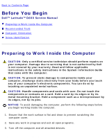
D600 Service Manual Back to Contents Page Before You Begin Dell™ Latitude™ D600 Service Manual Preparing to Work Inside the Computer Recommended Tools Computer Orientation Screw Identification Preparing to Work Inside the Computer CAUTION: Only a certified service technician should perform repairs - Dell Latitude D600 | Service Manual - Page 3
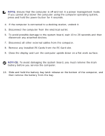
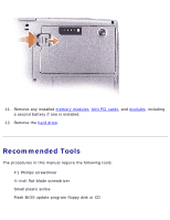
Before You Begin: Dell Latitude D600 Service Manual NOTE: Ensure that the remove the main battery before you service the computer. 10. Slide and hold the battery-bay latch release on the bottom of the computer, and then remove the battery from the bay. file:///F|/Service%20Manuals/Dell/Latitude/d600 - Dell Latitude D600 | Service Manual - Page 4
installed. 12. Remove the hard drive. Recommended Tools The procedures in this manual require the following tools: q #1 Phillips screwdriver q ¼-inch flat-blade screwdriver q Small plastic scribe q Flash BIOS update program floppy disk or CD file:///F|/Service%20Manuals/Dell/Latitude/d600/begin.htm - Dell Latitude D600 | Service Manual - Page 5
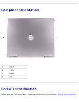
Before You Begin: Dell Latitude D600 Service Manual Computer Orientation 1 back 2 right 3 front 4 left Screw Identification When you are removing and replacing components, photocopy "Screw Identification" file:///F|/Service%20Manuals/Dell/Latitude/d600/begin.htm (4 of 7) [2/28/2004 8:15:41 - Dell Latitude D600 | Service Manual - Page 6
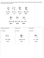
Before You Begin: Dell Latitude D600 Service Manual as a tool to lay out and keep track of the screws. The placemat provides the number of screws and their sizes. Optional Module: (1 each) Hard Drive: (1 each) Keyboard: (2 each) file:///F|/Service%20Manuals/Dell/Latitude/d600/begin.htm (5 of 7) - Dell Latitude D600 | Service Manual - Page 7
Before You Begin: Dell Latitude D600 Service Manual Display Assembly: Display Bezel: (3 each) (6 each) Display Panel: (4 each) Display Latch: (2 each) Palm Rest: (3 each) Fan: (2 each) (9 each) file:///F|/Service%20Manuals/Dell/Latitude/d600/begin.htm (6 of 7) [2/28/2004 8:15:41 AM] - Dell Latitude D600 | Service Manual - Page 8
Before You Begin: Dell Latitude D600 Service Manual Speakers: Modem: (1 each) (1 each) System Board: (1 each) (1 each) (1 each) (4 each) Back to Contents Page file:///F|/Service%20Manuals/Dell/Latitude/d600/begin.htm (7 of 7) [2/28/2004 8:15:41 AM] - Dell Latitude D600 | Service Manual - Page 9
that is not authorized by Dell is not covered by your warranty. NOTICE: Unless otherwise noted, each procedure in this document assumes that a part can be replaced by performing the removal procedure in reverse order. file:///F|/Service%20Manuals/Dell/Latitude/d600/system.htm (1 of 2) [2/28/2004 - Dell Latitude D600 | Service Manual - Page 10
: Dell Latitude D600 Service Manual 1 display assembly See MINI RSL 8 speakers 2N406 2 center control cover 8M659 9 hard drive See MINI RSL 3 palm rest 6M859 10 modem Y0231 4 system board U0996 11 thermal cooling assembly 2N403 5 computer base F1727 12 fan 4R197 6 battery 0R160 - Dell Latitude D600 | Service Manual - Page 11
: Dell Latitude D600 Service Manual Back to Contents Page Memory Module, Mini PCI Card, and Modules Dell™ Latitude™ D600 Service Manual Memory Module Mini PCI Card Modules Memory Module CAUTION: Before working inside your Dell™ computer, read the safety instructions in your System Information Guide - Dell Latitude D600 | Service Manual - Page 12
Card, and Modules: Dell Latitude D600 Service Manual NOTICE: To prevent damage to the memory module connector, do not use tools to spread the inner metal tabs that secure the memory module. 3. If you are replacing a memory module, remove the existing module. NOTICE: Handle memory modules by their - Dell Latitude D600 | Service Manual - Page 13
does not boot. No error message indicates this failure. 5. Replace the cover and screw. NOTICE: If the memory module cover is difficult to close, remove the module and reinstall it. Forcing the cover to close may damage your computer. file:///F|/Service%20Manuals/Dell/Latitude/d600/upgrades.htm - Dell Latitude D600 | Service Manual - Page 14
Card, and Modules: Dell Latitude D600 Service Manual 6. Insert the battery into the battery bay, or connect the AC adapter to your computer and an electrical outlet. 7. Turn on the computer. As the computer boots, it detects the additional memory and automatically updates the system configuration - Dell Latitude D600 | Service Manual - Page 15
Memory Module, Mini PCI Card, and Modules: Dell Latitude D600 Service Manual 3. Place your finger under the cover at the indentation, and lift and slide the cover open. file:///F|/Service%20Manuals/Dell/Latitude/d600/upgrades.htm (5 of 10) [2/28/2004 8:15:43 AM] - Dell Latitude D600 | Service Manual - Page 16
Memory Module, Mini PCI Card, and Modules: Dell Latitude D600 Service Manual 4. If a Mini PCI card is not already installed, go to step 5. If you are replacing a Mini PCI card, remove the existing card: a. Disconnect the Mini PCI card from any attached cables. b. Release the Mini PCI card by - Dell Latitude D600 | Service Manual - Page 17
Memory Module, Mini PCI Card, and Modules: Dell Latitude D600 Service Manual 2 antenna connectors on card (2) 7. Lower the Mini PCI card toward the inner tabs to approximately a 20-degree angle. 8. Continue lowering the Mini PCI card until it snaps into the inner tabs of the connector. 9. Replace - Dell Latitude D600 | Service Manual - Page 18
Memory Module, Mini PCI Card, and Modules: Dell Latitude D600 Service Manual 1 device latch release 2. Pull the device by the latch release to remove the device from the module bay. file:///F|/Service%20Manuals/Dell/Latitude/d600/upgrades.htm (8 of 10) [2/28/2004 8:15:43 AM] - Dell Latitude D600 | Service Manual - Page 19
Memory Module, Mini PCI Card, and Modules: Dell Latitude D600 Service Manual If the Device Security Screw Is Installed 1. If the computer is connected to a docking device (docked), undock it. See the documentation that came with your docking device for instructions. NOTICE: To prevent damage to - Dell Latitude D600 | Service Manual - Page 20
Memory Module, Mini PCI Card, and Modules: Dell Latitude D600 Service Manual Back to Contents Page file:///F|/Service%20Manuals/Dell/Latitude/d600/upgrades.htm (10 of 10) [2/28/2004 8:15:43 AM] - Dell Latitude D600 | Service Manual - Page 21
Reserve Battery: Dell Latitude D600 Service Manual Back to Contents Page Reserve Battery Dell™ Latitude™ D600 Service Manual CAUTION: Before working inside your Dell™ computer, read the safety instructions in your System Information Guide. CAUTION: To prevent static damage to components inside your - Dell Latitude D600 | Service Manual - Page 22
Reserve Battery: Dell Latitude D600 Service Manual 1 reserve battery 6R456 cover 4. Pull the reserve battery straight out of the computer base. 5. Disconnect the reserve battery cable connector from the speaker connector. 1 speaker connector 2 reserve battery Back to Contents Page D1004 file - Dell Latitude D600 | Service Manual - Page 23
Page Hard Drive Dell™ Latitude™ D600 Service Manual CAUTION: If you remove the hard drive from the computer when the drive is hot, do not touch the metal housing of the hard drive. CAUTION: Before working inside your computer, read the safety instructions in your System Information Guide. NOTICE - Dell Latitude D600 | Service Manual - Page 24
Hard Drive: Dell Latitude D600 Service Manual 1 M2.5 x 5-mm screw 63PDH NOTICE: If you do not open the display before you remove your hard drive, you might permanently scratch your display. 3. Open the display approximately 1/2 inch, as shown in the following figure. NOTICE: When the hard drive - Dell Latitude D600 | Service Manual - Page 25
Hard Drive: Dell Latitude D600 Service Manual 5. Remove the new drive from its packaging. Save the original packaging to use when storing or shipping the hard drive. NOTICE: If you do not open the display before you replace your hard drive, you might permanently scratch your display bezel. 6. Open - Dell Latitude D600 | Service Manual - Page 26
Hard Drive: Dell Latitude D600 Service Manual Back to Contents Page file:///F|/Service%20Manuals/Dell/Latitude/d600/hdd.htm (4 of 4) [2/28/2004 8:15:45 AM] - Dell Latitude D600 | Service Manual - Page 27
Keyboard: Dell Latitude D600 Service Manual Back to Contents Page Keyboard Dell™ Latitude™ D600 Service Manual CAUTION: Before performing the following procedures, read the safety instructions in your System Information Guide. NOTICE: To avoid electrostatic discharge, ground yourself by using a - Dell Latitude D600 | Service Manual - Page 28
Keyboard: Dell Latitude D600 Service Manual 1 display 2 center control cover 3 computer base 3. Remove the center control cover: a. Open the display all the way (180 degrees) so that it lies flat against your work surface. b. Starting on the right side of the computer, use a plastic scribe to pry up - Dell Latitude D600 | Service Manual - Page 29
Keyboard: Dell Latitude D600 Service Manual 1 center control cover 8M659 4. Remove the keyboard: a. Remove the two M2.5 x 6-mm screws across the top of the keyboard. NOTICE: The keycaps on the keyboard are fragile, easily dislodged, and timeconsuming to replace. Be careful when removing and - Dell Latitude D600 | Service Manual - Page 30
Keyboard: Dell Latitude D600 Service Manual NOTE: When you replace the keyboard, ensure that the keyboard tabs are completely in place to avoid scratching the palmrest. 1 M2.5 x 6-mm screws (2) 2 keyboard tabs 3 palm rest Back to Contents Page 057HW file:///F|/Service%20Manuals/Dell/Latitude/d600 - Dell Latitude D600 | Service Manual - Page 31
Service Manual Back to Contents Page Display Assembly and Display Latch Dell™ Latitude™ D600 Service Manual Display Assembly Display Bezel Display Panel Display Latch Display Assembly CAUTION: Before performing the following procedures, read the safety instructions in your System Information Guide - Dell Latitude D600 | Service Manual - Page 32
Display Assembly and Display Latch: Dell Latitude D600 Service Manual 1 M2.5 x 6-mm screws (3) 2 display cable connector 3 display 4 computer base 5 pull-tab 6 connector 057HW file:///F|/Service%20Manuals/Dell/Latitude/d600/display.htm (2 of 10) [2/28/2004 8:15:47 AM] - Dell Latitude D600 | Service Manual - Page 33
Display Assembly and Display Latch: Dell Latitude D600 Service Manual 1 display 2 cable-routing clips (4) 3 display cable connector 5. Pull up on the pull-tab that is attached to the display cable connector to remove the connector from the system board. 6. Remove the three M2.5 x 6-mm screws. 7. - Dell Latitude D600 | Service Manual - Page 34
Display Assembly and Display Latch: Dell Latitude D600 Service Manual 1 display 2 computer base file:///F|/Service%20Manuals/Dell/Latitude/d600/display.htm (4 of 10) [2/28/2004 8:15:47 AM] - Dell Latitude D600 | Service Manual - Page 35
Display Assembly and Display Latch: Dell Latitude D600 Service Manual 1 display bumpers (6) 6R933 2 M2 x 5-mm screws (6) 1428U 5 top cover 6 flex-cable retention bracket 8M669 4270E file:///F|/Service%20Manuals/Dell/Latitude/d600/display.htm (5 of 10) [2/28/2004 8:15:47 AM] - Dell Latitude D600 | Service Manual - Page 36
and Display Latch: Dell Latitude D600 Service Manual 3 display bezel 4 display panel 6M873 7 flex cable See MINI RSL 8 M2 x 5-mm screws (4) 6M871 Display Bezel CAUTION: Before performing the following procedures, read the safety instructions in your System Information Guide. NOTICE: To avoid - Dell Latitude D600 | Service Manual - Page 37
Display Assembly and Display Latch: Dell Latitude D600 Service Manual CAUTION: Before performing the following procedures, read the safety instructions in your System Information Guide. NOTICE: To avoid electrostatic discharge, ground yourself by using a wrist grounding strap or by touching an - Dell Latitude D600 | Service Manual - Page 38
Display Assembly and Display Latch: Dell Latitude D600 Service Manual 1 display panel 2 display side brackets (2) 3 M2 x 3-mm screws (4) See MINI RSL 8T145 4270E 5. Remove the two M2 x 5-mm screws from each side of the display panel. 6. Unsnap the cable from the top cover hook, and lift the - Dell Latitude D600 | Service Manual - Page 39
, and remove any installed batteries. NOTICE: Remove the display bezel. 4. Remove the two M2.5 x 4-mm screws that secure the display latch bracket to the top cover. 5. Lift the display bracket out of the top cover, and then remove the display latch. file:///F|/Service%20Manuals/Dell/Latitude/d600 - Dell Latitude D600 | Service Manual - Page 40
Display Assembly and Display Latch: Dell Latitude D600 Service Manual 1 top cover 2 M2.5 x 4-mm screws (2) 3 display latch bracket Back to Contents Page 8M669 6240E file:///F|/Service%20Manuals/Dell/Latitude/d600/display.htm (10 of 10) [2/28/2004 8:15:47 AM] - Dell Latitude D600 | Service Manual - Page 41
Palm Rest: Dell Latitude D600 Service Manual Back to Contents Page Palm Rest Dell™ Latitude™ D600 Service Manual CAUTION: Before performing the following procedures, read the safety instructions in your System Information Guide. NOTICE: To avoid electrostatic discharge, ground yourself by using a - Dell Latitude D600 | Service Manual - Page 42
Palm Rest: Dell Latitude D600 Service Manual 1 M2 x 3-mm screws (3) 2 top of the palm rest 4270E 5. Disconnect the touch pad connector from the system board. file:///F|/Service%20Manuals/Dell/Latitude/d600/palmrest.htm (2 of 4) [2/28/2004 8:15:48 AM] - Dell Latitude D600 | Service Manual - Page 43
Palm Rest: Dell Latitude D600 Service Manual 1 back center of the palm rest 2 touch pad connector 3 system board connector 4 computer base 6. Turn the computer over and remove the nine M2.5 x 8-mm screws. file:///F|/Service%20Manuals/Dell/Latitude/d600/palmrest.htm (3 of 4) [2/28/2004 8:15:48 AM] - Dell Latitude D600 | Service Manual - Page 44
Palm Rest: Dell Latitude D600 Service Manual 1 M2.5 x 8-mm screws (9) 3R690 NOTICE: Carefully separate the palm rest from the computer base rest while pushing in on the outside. Back to Contents Page file:///F|/Service%20Manuals/Dell/Latitude/d600/palmrest.htm (4 of 4) [2/28/2004 8:15:48 AM] - Dell Latitude D600 | Service Manual - Page 45
Docking Doors: Dell Latitude D600 Service Manual Back to Contents Page Docking Doors Dell™ Latitude™ D600 Service Manual Removing the Docking Doors CAUTION: Before working inside your computer, read the safety instructions in your System Information Guide. NOTICE: To avoid electrostatic discharge, - Dell Latitude D600 | Service Manual - Page 46
Docking Doors: Dell Latitude D600 Service Manual Installing the Docking Doors Slide the side of the docking covers with the spring over the longer posts. 1 docking doors with spring 2 longer post Back to Contents Page 7R316 file:///F|/Service%20Manuals/Dell/Latitude/d600/dockdoor.htm (2 of 2) [2/ - Dell Latitude D600 | Service Manual - Page 47
Fan: Dell Latitude D600 Service Manual Back to Contents Page Fan Dell™ Latitude™ D600 Service Manual CAUTION: Before performing the following procedures, read the safety instructions in your System Information Guide. NOTICE: To avoid electrostatic discharge, ground yourself by using a wrist - Dell Latitude D600 | Service Manual - Page 48
Fan: Dell Latitude D600 Service Manual 1 M2.5 x 8-mm screws (2) 2 fan 3 fan cable connector 4 system board connector 3R690 4R197 6. Remove the two M2.5 x 8-mm screws from the fan, and pull the fan away from the system board. file:///F|/Service%20Manuals/Dell/Latitude/d600/fan.htm (2 of 3) [2/28/ - Dell Latitude D600 | Service Manual - Page 49
Fan: Dell Latitude D600 Service Manual Back to Contents Page file:///F|/Service%20Manuals/Dell/Latitude/d600/fan.htm (3 of 3) [2/28/2004 8:15:49 AM] - Dell Latitude D600 | Service Manual - Page 50
Bluetooth™ Card: Dell Latitude D600 Service Manual Back to Contents Page Bluetooth™ Card Dell™ Latitude™ D600 Service Manual CAUTION: Before performing the following procedures, read the safety instructions in your System Information Guide. NOTICE: To avoid electrostatic discharge, ground yourself - Dell Latitude D600 | Service Manual - Page 51
Bluetooth™ Card: Dell Latitude D600 Service Manual 1 Bluetooth card 2 system board connector Back to Contents Page 1U746 file:///F|/Service%20Manuals/Dell/Latitude/d600/blue.htm (2 of 2) [2/28/2004 8:15:50 AM] - Dell Latitude D600 | Service Manual - Page 52
Dell Latitude D600 Service Manual Back to Contents Page Microprocessor Thermal-Cooling Assembly Dell™ Latitude™ D600 Service Manual Removing the Microprocessor Thermal-Cooling Assembly CAUTION: Before performing the following procedures, read the safety instructions in your System Information Guide - Dell Latitude D600 | Service Manual - Page 53
Microprocessor Thermal-Cooling Assembly: Dell Latitude D600 Service Manual 1 microprocessor thermal-cooling assembly 2 captive screws (4) 2N403 4. Rotate the microprocessor thermal-cooling assembly up toward the side of the computer and away from the system - Dell Latitude D600 | Service Manual - Page 54
Microprocessor Thermal-Cooling Assembly: Dell Latitude D600 Service Manual Back to Contents Page file:///F|/Service%20Manuals/Dell/Latitude/d600/thermal.htm (3 of 3) [2/28/2004 8:15:50 AM] - Dell Latitude D600 | Service Manual - Page 55
Microprocessor Module: Dell Latitude D600 Service Manual Back to Contents Page Microprocessor Module Dell™ Latitude™ D600 Service Manual Removing the Microprocessor Module CAUTION: Before performing the following procedures, read the safety instructions in your System Information Guide. NOTICE: To - Dell Latitude D600 | Service Manual - Page 56
Microprocessor Module: Dell Latitude D600 Service Manual 1 screwdriver (perpendicular to microprocessor) 2 ZIF-socket cam screw 3 ZIF socket for microprocessor part numbers. 5. Lift out the microprocessor module. file:///F|/Service%20Manuals/Dell/Latitude/d600/cpu.htm (2 of 3) [2/28/2004 8:15:51 AM] - Dell Latitude D600 | Service Manual - Page 57
board. 3. Replace the other computer parts you removed earlier in this procedure. 4. Update the BIOS using a flash BIOS update program floppy disk or CD. For instructions on how to flash the BIOS, see "Flashing the BIOS." Back to Contents Page file:///F|/Service%20Manuals/Dell/Latitude/d600/cpu.htm - Dell Latitude D600 | Service Manual - Page 58
to reset the computer defaults. 5. Press , select Save changes and reboot, and press configuration changes. to save 6. Remove the flash BIOS update program floppy disk or CD from the drive and restart the computer. Back to Contents Page file:///F|/Service%20Manuals/Dell/Latitude/d600/bios.htm - Dell Latitude D600 | Service Manual - Page 59
Speakers: Dell Latitude D600 Service Manual Back to Contents Page Speakers Dell™ Latitude™ D600 Service Manual CAUTION: Before performing the following procedures, read the safety instructions in your System Information Guide. NOTICE: To avoid electrostatic discharge, ground yourself by using a - Dell Latitude D600 | Service Manual - Page 60
Speakers: Dell Latitude D600 Service Manual 1 speaker 2 speaker connector 3 system board connector 4 reserve battery 2N406 3R459 5 M2.5 x 4-mm screw 6 computer base 7 M2.5 x 8-mm screw 6240E 3R690 Back to Contents Page file:///F|/Service%20Manuals/Dell/Latitude/d600/speakers.htm (2 of 2) [2/28 - Dell Latitude D600 | Service Manual - Page 61
instructions in "Preparing to Work Inside the Computer." 2. Remove the hard drive. 3. Remove the keyboard. 4. Remove the display assembly. 5. Remove the palm rest. 6. Remove the speakers. 7. Pull the base latch straight up and away from the computer base. file:///F|/Service%20Manuals/Dell/Latitude - Dell Latitude D600 | Service Manual - Page 62
Base Latch: Dell Latitude D600 Service Manual 1 base latch 2 computer base Back to Contents Page 1N487 file:///F|/Service%20Manuals/Dell/Latitude/d600/latch.htm (2 of 2) [2/28/2004 8:15:53 AM] - Dell Latitude D600 | Service Manual - Page 63
Modem: Dell Latitude D600 Service Manual Back to Contents Page Modem Dell™ Latitude™ D600 Service Manual CAUTION: Before performing the following procedures, read the safety instructions in your System Information Guide. NOTICE: To avoid electrostatic discharge, ground yourself by using a wrist - Dell Latitude D600 | Service Manual - Page 64
Modem: Dell Latitude D600 Service Manual 1 modem 2 pull-tab 3 M2 x 3-mm screw Y0231 4270E 4 system board connector 5 modem NOTICE: Ensure that the modem cable is routed correctly when you replace the modem. file:///F|/Service%20Manuals/Dell/Latitude/d600/modem.htm (2 of 3) [2/28/2004 8:15:53 AM] - Dell Latitude D600 | Service Manual - Page 65
Modem: Dell Latitude D600 Service Manual 1 modem 2 modem cable Back to Contents Page file:///F|/Service%20Manuals/Dell/Latitude/d600/modem.htm (3 of 3) [2/28/2004 8:15:53 AM] - Dell Latitude D600 | Service Manual - Page 66
System Board: Dell Latitude D600 Service Manual Back to Contents Page System Board Dell™ Latitude™ D600 Service Manual Removing the System Board CAUTION: Before performing the following procedures, read the safety instructions in your System Information Guide. NOTICE: To avoid electrostatic - Dell Latitude D600 | Service Manual - Page 67
System Board: Dell Latitude D600 Service Manual 8. Remove the one M2.5 x 8-mm screw and one M2.5 x 4-mm screw labeled "circle B." 1 M2.5 x 4-mm screw 2 M2.5 x 8-mm screw 3 system board 6240E 3R690 U0996 file:///F|/Service%20Manuals/Dell/Latitude/d600/sysboard.htm (2 of 4) [2/28/2004 8:15:54 AM] - Dell Latitude D600 | Service Manual - Page 68
in "Removing the System Board" in reverse order. NOTICE: Before turning on the computer, replace all screws and ensure that no stray screws remain inside the computer. Failure to do so may result in damage to the computer. 2. Turn on the computer. file:///F|/Service%20Manuals/Dell/Latitude/d600 - Dell Latitude D600 | Service Manual - Page 69
: Dell Latitude D600 Service Manual NOTE: After replacing the system board, enter the computer Service Tag sequence into the BIOS of the replacement system board. 3. Insert the floppy disk or CD that accompanied the replacement system board into the appropriate drive. Follow the instructions that - Dell Latitude D600 | Service Manual - Page 70
Latitude D600 Service Manual Back to Contents Page Pin Assignments for I/O Connectors Dell™ Latitude™ D600 Service Manual USB Connector Video Connector Parallel Connector USB Connector Pin Signal 1 USB5V+ 2 USBP- 3 USBP+ 4 GND Video Connector file:///F|/Service%20Manuals/Dell/Latitude - Dell Latitude D600 | Service Manual - Page 71
Connectors: Dell Latitude D600 Service Manual Pin Signal Pin Signal 1 CRT_R 9 5V+ 2 CRT_G 10 GND 3 CRT_B 11 MONITOR_DETECT- 4 NC 12 DDC_DATA 5 GND 13 CRT_HS 6 GND 14 CRT_VS 7 GND 15 DDC_CLK 8 GND Parallel Connector file:///F|/Service%20Manuals/Dell/Latitude/d600/pinouts - Dell Latitude D600 | Service Manual - Page 72
: Dell Latitude D600 Service Manual Pin Signal Pin Signal 1 STROBE- 2 PD0 3 PD1 4 PD2 5 PD3 6 PD4 7 PD5 8 PD6 9 PD7 10 11 12 13 14 15 16 17 18-25 ACK- BUSY PE SLCT AFD/3M- ERROR- INIT- SLIN- GND Back to Contents Page file:///F|/Service%20Manuals/Dell/Latitude/d600/pinouts - Dell Latitude D600 | Service Manual - Page 73
Mini Recommended Spares List: Dell Latitude D600 Service Manual Back to Contents Page Mini Recommended Spares List Dell™ Latitude™ D600 Service Manual NOTE: The part numbers listed below are subject to change. Bottom Base Parts N0441 7R843 N0312 2N401 F1727 1N487 memory door Mini PCI card door - Dell Latitude D600 | Service Manual - Page 74
Mini Recommended Spares List: Dell Latitude D600 Service Manual Fan 4R197 fan Floppy Drive 2R152 floppy drive, D-module Hard Drive and Accessories 8X209 8X210 8X211 7X889 7T651 20 G HDD 30 G HDD 40 G HDD 60 G HDD 40 G HDD, D-module, second HDD (HDD and DMOD housing) 0R854 - Dell Latitude D600 | Service Manual - Page 75
List: Dell Latitude D600 Service Manual 8M659 057HW center control cover M2.5 x 6-mm screw LCD Display Assembly D1001 D1002 3Y530 6M873 8M669 14.1 XGA panel with LCD cable 14.1 SXGA+ panel with LCD cable display latch, D600 display bezel top cover, 14.1 inch (includes latch and hinges) Memory - Dell Latitude D600 | Service Manual - Page 76
Mini Recommended Spares List: Dell Latitude D600 Service Manual 3R459 reserve battery 5U092 9T215 1T831 5T327 4X511 H0286 AC power brick only, 65 W AC power brick only, 90 W (must be used with D-Dock and D-Port) power cord, - Dell Latitude D600 | Service Manual - Page 77
Mini Recommended Spares List: Dell Latitude D600 Service Manual Wireless 3X548 9Y200 J0846 TM1400 Dual-band a/b Combo Card MPCI Intel® Pro Wireless 2100 802.11b MPCI TM1300 802.11b/g MPCI Back to Contents Page file:///F|/Service%20Manuals/Dell/Latitude/d600/minirsl.htm (5 of 5) [2/28/2004 8:15:
-
 1
1 -
 2
2 -
 3
3 -
 4
4 -
 5
5 -
 6
6 -
 7
7 -
8
-
9
-
10
-
11
-
12
-
13
-
14
-
15
-
16
-
17
-
18
-
19
-
20
-
21
-
22
-
23
-
24
-
25
-
26
-
27
-
28
-
29
-
30
-
31
-
32
-
33
-
34
-
35
-
36
-
37
-
38
-
39
-
40
-
41
-
42
-
43
-
44
-
45
-
46
-
47
-
48
-
49
-
50
-
51
-
52
-
53
-
54
-
55
-
56
-
57
-
58
-
59
-
60
-
61
-
62
-
63
-
64
-
65
-
66
-
67
-
68
-
69
-
70
-
71
-
72
-
73
-
74
-
75
-
76
-
77
 |
 |
Dell Latitude D600 Service Manual
Dell™ Latitude™ D600 Service Manual
Before You Begin
System Components
Memory Module, Mini PCI Card, and Modules
Reserve Battery
Hard Drive
Keyboard
Display Assembly and Display Latch
Palm Rest
Docking Doors
Fan
Bluetooth™ Card
Microprocessor Thermal-Cooling Assembly
Microprocessor Module
Flashing the BIOS
Speakers
Base Latch
Modem
System Board
Pin Assignments for I/O Connectors
Mini Recommended Spares List
Notes, Notices, and Cautions
NOTE:
A NOTE indicates important information that helps you make better use
of your computer.
NOTICE:
A NOTICE indicates either potential damage to hardware or loss of
data and tells you how to avoid the problem.
CAUTION:
A CAUTION indicates a potential for property damage,
personal injury, or death.
file:///F|/Service%20Manuals/Dell/Latitude/d600/index.htm (1 of 2) [2/28/2004 8:15:34 AM]