Dell Latitude E6400 Service Manual
Dell Latitude E6400 Manual
 |
View all Dell Latitude E6400 manuals
Add to My Manuals
Save this manual to your list of manuals |
Dell Latitude E6400 manual content summary:
- Dell Latitude E6400 | Service Manual - Page 1
Dell™ Latitude™ E6400 and E6400 ATG and Mobile Workstation Precision™ M2400 Service Manual Troubleshooting Working on Your Computer Base Assembly Hinge Covers Hard Drive WLAN/WiMax Card WWAN Card WPAN (UWB/BT) Card FCM Fan Processor Heatsink Assembly Processor Module Memory Coin-Cell Battery - Dell Latitude E6400 | Service Manual - Page 2
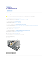
Back to Contents Page 1394 Card Dell™ Latitude™ E6400 and E6400 ATG and Mobile Workstation Precision™ M2400 Service Manual Removing the 1394 Card Replacing the 1394 Card Removing the 1394 Card CAUTION: Before you begin the following procedure, follow the safety instructions that shipped with your - Dell Latitude E6400 | Service Manual - Page 3
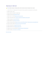
Assembly (E6400 ATG)). 10. Replace the heatsink assembly (see Replacing the Processor Heatsink Assembly). 11. Replace the hinge covers (see Replacing the Hinge Covers). 12. Replace the modular drive (see Replacing the Modular Drive). 13. Replace the bottom of the base assembly (see Replacing the - Dell Latitude E6400 | Service Manual - Page 4
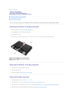
Back to Contents Page Base Assembly Dell™ Latitude™ E6400 and E6400 ATG and Mobile Workstation Precision™ M2400 Service Manual Removing the Bottom of the Base Assembly Replacing the Bottom of the Base Assembly Removing the Base Assembly Replacing the Base Assembly CAUTION: Before you begin any of - Dell Latitude E6400 | Service Manual - Page 5
the Keyboard). 10. Replace the LED cover (see Replacing the LED Cover). 11. Replace the display assembly (see Replacing the Display Assembly (E6400 and M2400) or Replacing the Display Assembly (E6400 ATG)). 12. Replace the modular drive (see Replacing the Modular Drive). 13. Replace the hard drive - Dell Latitude E6400 | Service Manual - Page 6
. Flash update the BIOS (see Flashing the BIOS for more information). 22. Enter the system setup program to update the BIOS on the new system board with the computer Service Tag. For information on the system setup program, see the Dell™ Technology Guide on your computer or at support.dell.com. Back - Dell Latitude E6400 | Service Manual - Page 7
Back to Contents Page Battery Latch Assembly Dell™ Latitude™ E6400 and E6400 ATG and Mobile Workstation Precision™ M2400 Service Manual Removing a Battery Latch Assembly Replacing the Battery Latch Assembly There are two battery latches, a left and a right, and each latch uses a unique latch - Dell Latitude E6400 | Service Manual - Page 8
1 spring 2 alignment bracket 3 M2 x 3-mm screws (2) 4 battery release button 5 base assembly Replacing the Battery Latch Assembly CAUTION: Before you begin the following procedure, follow the safety instructions that shipped with your computer. 1. Place the spring on the alignment bracket. 2. - Dell Latitude E6400 | Service Manual - Page 9
17. Replace the hard drive (see Replacing the Hard Drive). 18. Replace the bottom of the base assembly (see Replacing the Bottom of the Base Assembly). 19. Follow the procedures in After Working on Your Computer. Back to Contents Page - Dell Latitude E6400 | Service Manual - Page 10
jack. 4. Disconnect any telephone or network cables from the computer. NOTICE: To help prevent damage to the system board, you must remove the battery from the battery bay before you service the computer. 5. Turn the computer upside down. 6. Slide the battery release latches toward each other to - Dell Latitude E6400 | Service Manual - Page 11
cards, such as an ExpressCard, see the Dell™ Technology Guide on your computer or at support.dell.com. l To undock from a docking station, see the E-Port User's Guide or the E-Port Plus User's Guide on support.dell.com. l To remove a battery slice, see the documentation that shipped with your - Dell Latitude E6400 | Service Manual - Page 12
4. Replace the battery. Slide the battery into the battery bay until it clicks into place. 5. Connect your computer and all attached devices to their electrical outlets. 6. Turn on your computer. Back to Contents Page - Dell Latitude E6400 | Service Manual - Page 13
Back to Contents Page Flashing the BIOS Dell™ Latitude™ E6400 and E6400 ATG and Mobile Workstation Precision™ M2400 Service Manual Flashing the BIOS From a CD Flashing the BIOS From the Hard Drive If a BIOS-update program CD is provided with a new system board, flash the BIOS from the CD. If you do - Dell Latitude E6400 | Service Manual - Page 14
- Dell Latitude E6400 | Service Manual - Page 15
Contents Page Card Cage Dell™ Latitude™ E6400 and E6400 ATG and Mobile Workstation Precision™ M2400 Service Manual Removing the Card Cage Replacing the Card Cage Removing the Card Cage CAUTION: Before you begin any of the procedures in this section, follow the safety instructions that shipped with - Dell Latitude E6400 | Service Manual - Page 16
or Replacing the Display Assembly (E6400 ATG)). 8. Replace the heatsink assembly (see Replacing the Processor Heatsink Assembly). 9. Replace the hinge covers (see Replacing the Hinge Covers). 10. Replace the modular drive (see Replacing the Modular Drive). 11. Replace the bottom of the base assembly - Dell Latitude E6400 | Service Manual - Page 17
-Cell Battery Dell™ Latitude™ E6400 and E6400 ATG and Mobile Workstation Precision™ M2400 Service Manual Removing the Coin-Cell Battery Replacing the Coin-Cell Battery Removing the Coin-Cell Battery CAUTION: Before you begin any of the procedures in this section, follow the safety instructions that - Dell Latitude E6400 | Service Manual - Page 18
1 coin-cell battery 2 coin-cell battery cable 3. Replace the bottom of the base assembly (see Replacing the Bottom of the Base Assembly). 4. Follow the procedures in After Working on Your Computer. Back to Contents Page - Dell Latitude E6400 | Service Manual - Page 19
Dell™ Latitude™ E6400 and E6400 ATG and Mobile Workstation Precision™ M2400 Service Manual Removing the Processor Module Replacing the Processor Module Removing the Processor Module CAUTION: Before you begin the following procedure, follow the safety instructions that shipped with your computer - Dell Latitude E6400 | Service Manual - Page 20
the ZIF socket by turning the cam screw clockwise to secure the processor module to the system board. 3. Replace the processor heatsink assembly (see Replacing the Processor Heatsink Assembly). 4. Replace the bottom of the base assembly (see Replacing the Bottom of the Base Assembly). 5. Follow the - Dell Latitude E6400 | Service Manual - Page 21
Dell™ Latitude™ E6400 and E6400 ATG and Mobile Workstation Precision™ M2400 Service Manual Removing the Processor Heatsink Assembly Replacing the Processor Heatsink Assembly Removing the Processor Heatsink Assembly CAUTION: Before you begin the following procedure, follow the safety instructions - Dell Latitude E6400 | Service Manual - Page 22
6. Follow the procedures in After Working on Your Computer. Back to Contents Page - Dell Latitude E6400 | Service Manual - Page 23
Back to Contents Page I/O Card Dell™ Latitude™ E6400 and E6400 ATG and Mobile Workstation Precision™ M2400 Service Manual Removing the I/O Card Replacing the I/O Card Removing the I/O Card CAUTION: Before you begin the following procedure, follow the safety instructions that shipped with your - Dell Latitude E6400 | Service Manual - Page 24
(E6400 ATG)). 13. Replace the heatsink assembly (see Replacing the Processor Heatsink Assembly). 14. Replace the hinge covers (see Replacing the Hinge Covers). 15. Replace the modular drive (see Replacing the Modular Drive). 16. Replace the hard drive (see Replacing the Hard Drive). 17. Replace the - Dell Latitude E6400 | Service Manual - Page 25
Back to Contents Page - Dell Latitude E6400 | Service Manual - Page 26
Display Assembly Dell™ Latitude™ E6400 and E6400 ATG and Mobile Workstation Precision™ M2400 Service Manual Removing the Display Assembly (E6400 and M2400) Replacing the Display Assembly (E6400 and M2400) Removing the Display Assembly (E6400 ATG) Replacing the Display Assembly (E6400 ATG) Removing - Dell Latitude E6400 | Service Manual - Page 27
Covers). 9. Replace the bottom of the base assembly (see Replacing the Bottom of the Base Assembly). 10. Follow the procedures in After Working on Your Computer. Removing the Display Assembly (E6400 ATG) CAUTION: Before you begin the following procedure, follow the safety instructions that shipped - Dell Latitude E6400 | Service Manual - Page 28
cable 6. Turn the computer topside up. 7. Open the display to 90 degrees and lift the display assembly off the base assembly. 1 display assembly 2 base assembly Replacing the Display Assembly (E6400 ATG) CAUTION: Before you begin the following procedure, follow the safety instructions that shipped - Dell Latitude E6400 | Service Manual - Page 29
Connect the touch screen cable to the touch screen connector on the system board. 8. Replace the two M2.5 x 5-mm screws on the hinges. 9. Replace the hinge covers (see Replacing the Hinge Covers). 10. Replace the bottom of the base assembly (see Replacing the Bottom of the Base Assembly). 11. Follow - Dell Latitude E6400 | Service Manual - Page 30
bezel 3 left side of display bezel 4 bottom of display bezel 5 display panel Replacing the Display Bezel (E6400 and M2400) CAUTION: Before you begin the following procedure, follow the safety instructions that shipped with your computer. 1. Align the latch hook on the display panel with the small - Dell Latitude E6400 | Service Manual - Page 31
Hinge Covers). 7. Replace the bottom of the base assembly (see Replacing the Bottom of the Base Assembly). 8. Follow the procedures in After Working on Your Computer. Removing the Display Bezel (E6400 ATG) CAUTION: Before you begin the following procedure, follow the safety instructions that shipped - Dell Latitude E6400 | Service Manual - Page 32
3 left side of display bezel 4 display panel 5 bottom of display bezel Replacing the Display Bezel (E6400 ATG) CAUTION: Before you begin the following procedure, follow the safety instructions that shipped with your computer. 1. Align the latch hook on the display panel with the small rectangular - Dell Latitude E6400 | Service Manual - Page 33
(see Removing the Bottom of the Base Assembly). 3. Remove the hinge covers (see Removing the Hinge Covers). 4. Remove the display assembly (see Removing the Display Assembly (E6400 and M2400)). 5. Remove the display bezel (see Removing the Display Bezel (E6400 and M2400)). 6. Remove the four M2 - Dell Latitude E6400 | Service Manual - Page 34
bottom of the base assembly (see Replacing the Bottom of the Base Assembly). 11. Follow the procedures in After Working on Your Computer. Removing the LED Display Panel and Brackets (E6400 and M2400) CAUTION: Before you begin the following procedure, follow the safety instructions that shipped with - Dell Latitude E6400 | Service Manual - Page 35
panel 9. Remove two M2 x 3-mm screws from the right bracket and two M2 x 3-mm screws from the left bracket. 1 display panel 2 brackets (2) 3 M2 x 3-mm screws (4) Replacing the LED Display Panel and Brackets (E6400 and M2400) - Dell Latitude E6400 | Service Manual - Page 36
the bottom of the base assembly (see Replacing the Bottom of the Base Assembly). 9. Follow the procedures in After Working on Your Computer. Removing the Display Panel and Brackets (E6400 ATG) CAUTION: Before you begin the following procedure, follow the safety instructions that shipped with your - Dell Latitude E6400 | Service Manual - Page 37
bracket. 1 display panel 2 bracket 3 M2 x 3-mm screws (8) Replacing the Display Panel and Brackets (E6400 ATG) CAUTION: Before you begin the following procedure, follow the safety instructions that shipped with your computer. NOTICE: On touch screen display panels, use care when installing the - Dell Latitude E6400 | Service Manual - Page 38
the bottom of the base assembly (see Replacing the Bottom of the Base Assembly). 11. Follow the procedures in After Working on Your Computer. Removing the Display Inverter (E6400 and M2400) CAUTION: Before you begin the following procedure, follow the safety instructions that shipped with your - Dell Latitude E6400 | Service Manual - Page 39
of the base assembly (see Replacing the Bottom of the Base Assembly). 7. Follow the procedures in After Working on Your Computer. Removing the Display Hinges (E6400 and M2400) CAUTION: Before you begin the following procedure, follow the safety instructions that shipped with your computer. NOTE: The - Dell Latitude E6400 | Service Manual - Page 40
of the base assembly (see Replacing the Bottom of the Base Assembly). 8. Follow the procedures in After Working on Your Computer. Removing the Display Hinges (E6400 ATG) CAUTION: Before you begin the following procedure, follow the safety instructions that shipped with your computer. 1. Follow the - Dell Latitude E6400 | Service Manual - Page 41
Panel and Brackets (E6400 ATG)). 4. Replace the display bezel (see Replacing the Display Bezel (E6400 ATG)). 5. Replace the display assembly (see Replacing the Display Assembly (E6400 ATG)). 6. Replace the hinge covers (see Replacing the Hinge Covers). 7. Replace the bottom of the base assembly (see - Dell Latitude E6400 | Service Manual - Page 42
or Replacing the Display Bezel (E6400 ATG)). 6. Replace the display assembly (see Replacing the Display Assembly (E6400 and M2400) or Replacing the Display Bezel (E6400 ATG)). 7. Replace the hinge covers (see Replacing the Hinge Covers). 8. Replace the bottom of the base assembly (see Replacing the - Dell Latitude E6400 | Service Manual - Page 43
or Replacing the Display Bezel (E6400 ATG)). 6. Replace the display assembly (see Replacing the Display Assembly (E6400 and M2400) or Replacing the Display Bezel (E6400 ATG)). 7. Replace the hinge covers (see Replacing the Hinge Covers). 8. Replace the bottom of the base assembly (see Replacing the - Dell Latitude E6400 | Service Manual - Page 44
the Display Bezel (E6400 ATG)). 4. Replace the display assembly (see Replacing the Display Assembly (E6400 and M2400) or Replacing the Display Assembly (E6400 ATG)). 5. Replace the hinge covers (see Replacing the Hinge Covers). 6. Replace the bottom of the base assembly (see Replacing the Bottom of - Dell Latitude E6400 | Service Manual - Page 45
the Display Bezel (E6400 ATG)). 4. Replace the display assembly (see Replacing the Display Assembly (E6400 and M2400) or Replacing the Display Assembly (E6400 ATG)). 5. Replace the hinge covers (see Replacing the Hinge Covers). 6. Replace the bottom of the base assembly (see Replacing the Bottom of - Dell Latitude E6400 | Service Manual - Page 46
Page Fan Dell™ Latitude™ E6400 and E6400 ATG and Mobile Workstation Precision™ M2400 Service Manual Removing the Fan Replacing the Fan Removing the Fan CAUTION: Before you begin the following procedure, follow the safety instructions that shipped with your computer. 1. Follow the instructions in - Dell Latitude E6400 | Service Manual - Page 47
Back to Contents Page - Dell Latitude E6400 | Service Manual - Page 48
Page FCM Dell™ Latitude™ E6400 and E6400 ATG and Mobile Workstation Precision™ M2400 Service Manual Removing an FCM from the WWAN/FCM Slot Removing an FCM from the WPAN/UWB/FCM Slot Replacing an FCM CAUTION: Before you begin any of the procedures in this section, follow the safety instructions that - Dell Latitude E6400 | Service Manual - Page 49
computer. NOTICE: The connectors are keyed to ensure correct insertion. If you feel resistance, check the connectors on the module and on the system card connector on the system board. 2. Press the FCM down and hold it in place. 3. Replace the M2 x blue antenna cable in the holder next to the module. - Dell Latitude E6400 | Service Manual - Page 50
1 holder by module 3 FCM 2 blue antenna cable 5. Replace the bottom of the base assembly (see Replacing the Bottom of the Base Assembly). 6. Follow the procedures in After Working on Your Computer. Back to Contents Page - Dell Latitude E6400 | Service Manual - Page 51
Hard Drive Dell™ Latitude™ E6400 and E6400 ATG and Mobile Workstation Precision™ M2400 Service Manual Removing the Hard Drive Replacing the Hard Drive Removing the 1.8" Hard Drive (E6400 ATG) Replacing the 1.8" Hard Drive (E6400 ATG) Removing the Modular Hard Drive Replacing the Modular Hard Drive - Dell Latitude E6400 | Service Manual - Page 52
in After Working on Your Computer. 7. Install the operating system, drivers, and utilities for your computer, as needed. For more information, see the Setup and Quick Reference Guide that shipped with your computer or at support.dell.com. Removing the 1.8" Hard Drive (E6400 ATG) CAUTION: Before you - Dell Latitude E6400 | Service Manual - Page 53
1 hard drive 2 bottom of base assembly 3 M3 x 3-mm screws (2) 5. Remove the M3 x 3-mm screw on the hard drive bezel. 6. Remove the hard drive bezel. 1 hard drive bezel 2 pin on bezel bracket 3 hard drive 4 M3 x 3-mm screw 7. Remove the two M2.5 x 5-mm screws from the cover of the hard drive - Dell Latitude E6400 | Service Manual - Page 54
bumper to remove it from the hard drive. 1 hard drive 2 blue bumper Replacing the 1.8" Hard Drive (E6400 ATG) CAUTION: Before you begin any of the procedures in this section, follow the safety instructions that shipped with your computer. NOTICE: Hard drives are extremely fragile. Exercise care when - Dell Latitude E6400 | Service Manual - Page 55
the hard drive to the base assembly. 10. Follow the procedures in After Working on Your Computer. 11. Install the operating system, drivers, and utilities for your computer, as needed. For more information, see the Setup and Quick Reference Guide that shipped with your computer at support.dell.com - Dell Latitude E6400 | Service Manual - Page 56
off your computer before removing the hard drive. Do not remove the hard drive while the computer is on or in Sleep state. NOTICE: Hard drives are extremely fragile. Exercise care when handling the hard drive. 1. Follow the procedures in Working on Your Computer. 2. Turn your computer upside down - Dell Latitude E6400 | Service Manual - Page 57
up at an angle and remove. 1 cover 2 M2.5 x 5-mm screws (3) 3 hard drive carrier 12. Remove the four M2.5 x 5 screws from the hard drive bracket. 1 hard drive carrier 2 M2.5 x 5-mm screws (4) 3 hard drive 4 hard drive bracket 13. Lift the hard drive up at an angle and disconnect it from the - Dell Latitude E6400 | Service Manual - Page 58
the hard drive. 1 hard drive 2 blue bumper Replacing the Modular Hard Drive CAUTION: Before you begin any of the procedures in this section, follow the safety instructions that shipped with your computer. NOTICE: Hard drives are extremely fragile. Exercise care when handling the hard drive. NOTICE - Dell Latitude E6400 | Service Manual - Page 59
1 hard drive 2 connector 3 hard drive bracket 4 corner of hard drive bracket (2) 4. Place the hard drive into the carrier at an angle. 5. Connect the hard drive to the connector in the carrier and lower the hard drive into the carrier. 1 hard drive 2 hard drive carrier 3 connector 6. Replace the - Dell Latitude E6400 | Service Manual - Page 60
notches on the carrier. 8. Set the cover in place and replace the three M2.5 x 5-mm screws. 1 notches in hard drive carrier 2 tabs on carrier cover 3 M2.5 x 5-mm screws (3) 9. Slide the release latch carrier into the hard drive carrier. 10. Replace the M2.5 x 5-mm screw that holds the carrier for - Dell Latitude E6400 | Service Manual - Page 61
modular drive, replace the security screw. 16. Follow the procedures in After Working on Your Computer. 17. Install the operating system, drivers, and utilities for your computer, as needed. For more information, see the Setup and Quick Reference Guide that shipped with your computer at support.dell - Dell Latitude E6400 | Service Manual - Page 62
Dell™ Latitude™ E6400 and E6400 ATG and Mobile Workstation Precision™ M2400 Service Manual Removing the Hinge Covers Replacing the Hinge Covers Removing the Hinge Covers CAUTION: Before you begin any of the procedures in this section, follow the safety instructions that shipped with your computer - Dell Latitude E6400 | Service Manual - Page 63
to Contents Page Keyboard Dell™ Latitude™ E6400 and E6400 ATG and Mobile Workstation Precision™ M2400 Service Manual Removing the Keyboard Replacing the Keyboard Removing the Keyboard CAUTION: Before you begin any of the procedures in this section, follow the safety instructions that shipped with - Dell Latitude E6400 | Service Manual - Page 64
1 M2 x 3-mm screws (2) 2 tabs (5) 3 keyboard connector 4. Replace the LED cover (see Replacing the LED Cover). 5. Follow the procedures in After Working on Your Computer. Back to Contents Page - Dell Latitude E6400 | Service Manual - Page 65
Contents Page LED Cover Dell™ Latitude™ E6400 and E6400 ATG and Mobile Workstation Precision™ M2400 Service Manual Removing the LED Cover Replacing the LED Cover Removing the LED Cover CAUTION: Before you begin any of the procedures in this section, follow the safety instructions that shipped with - Dell Latitude E6400 | Service Manual - Page 66
Back to Contents Page - Dell Latitude E6400 | Service Manual - Page 67
Page Memory Dell™ Latitude™ E6400 and E6400 ATG and Mobile Workstation Precision™ M2400 Service Manual Removing a Memory Module Replacing a Memory Module Your computer has two user-accessible SODIMM sockets. You can increase your computer memory by installing memory modules on the system board - Dell Latitude E6400 | Service Manual - Page 68
(see Replacing the Bottom of the Base Assembly). 4. Follow the procedures in After Working on Your Computer. As the computer boots, it detects the additional memory and automatically updates the system configuration information. To confirm the amount of memory installed in the computer: l In Windows - Dell Latitude E6400 | Service Manual - Page 69
to Contents Page Modem Dell™ Latitude™ E6400 and E6400 ATG and Mobile Workstation Precision™ M2400 Service Manual Removing the Modem Replacing the Modem Removing the Modem CAUTION: Before you begin the following procedure, follow the safety instructions that shipped with your computer. 1. Follow the - Dell Latitude E6400 | Service Manual - Page 70
Back to Contents Page - Dell Latitude E6400 | Service Manual - Page 71
Back to Contents Page Modular Drive Dell™ Latitude™ E6400 and E6400 ATG and Mobile Workstation Precision™ M2400 Service Manual Removing the Modular Drive Replacing the Modular Drive The modular drive supports either a second hard drive, an optical drive, or a an air bay for travel. Removing the - Dell Latitude E6400 | Service Manual - Page 72
Rest Assembly Dell™ Latitude™ E6400 and E6400 ATG and Mobile Workstation Precision™ M2400 Service Manual Removing the Palm Rest Assembly Replacing the Palm Rest Assembly Removing the Palm Rest Assembly CAUTION: Before you begin the following procedure, follow the safety instructions that shipped - Dell Latitude E6400 | Service Manual - Page 73
the keyboard (see Replacing the Keyboard). 8. Replace the LED cover (see Replacing the LED Cover). 9. Replace the display assembly (see Replacing the Display Assembly (E6400 and M2400) or Replacing the Display Assembly (E6400 ATG)). 10. Replace the modular drive (see Replacing the Modular Drive). 11 - Dell Latitude E6400 | Service Manual - Page 74
Page DC Power Cable Dell™ Latitude™ E6400 and E6400 ATG and Mobile Workstation Precision™ M2400 Service Manual Removing the DC Power Cable Replacing the DC Power Cable Removing the DC Power Cable CAUTION: Before you begin the following procedure, follow the safety instructions that shipped with your - Dell Latitude E6400 | Service Manual - Page 75
the safety instructions that shipped with your computer. 1. Place the DC power cable in the base assembly, aligning the guides on the connector sides with the base. 2. Route the DC power cable in the base assembly. 3. Replace the system board (see Replacing the System Board Assembly). 4. Replace the - Dell Latitude E6400 | Service Manual - Page 76
Modem Connector Dell™ Latitude™ E6400 and E6400 ATG and Mobile Workstation Precision™ M2400 Service Manual Removing the RJ-11 Modem Connector Replacing the RJ-11 Modem Connector Removing the RJ-11 Modem Connector CAUTION: Before you begin the following procedure, follow the safety instructions that - Dell Latitude E6400 | Service Manual - Page 77
(see Replacing the Keyboard). 6. Replace the LED cover (see Replacing the LED Cover). 7. Replace the display assembly (see Replacing the Display Assembly (E6400 and M2400) or Replacing the Display Assembly (E6400 ATG)). 8. Replace the modular drive (see Replacing the Modular Drive). 9. Replace the - Dell Latitude E6400 | Service Manual - Page 78
Back to Contents Page Right Speaker Grill/Fingerprint Reader Assembly Dell™ Latitude™ E6400 and E6400 ATG and Mobile Workstation Precision™ M2400 Service Manual Removing the Right Speaker Grill/Fingerprint Reader Assembly Replacing the Right Speaker Grill/Fingerprint Reader Assembly NOTE: The - Dell Latitude E6400 | Service Manual - Page 79
to the palm rest. 3. Replace the keyboard (see Replacing the Keyboard). 4. Replace the LED cover (see Replacing the LED Cover). 5. Turn the computer upside down, and tighten the two M2.5 x 5-mm screws in the modular bay. 6. Replace the modular drive (see Replacing the Modular Drive). 7. Follow the - Dell Latitude E6400 | Service Manual - Page 80
Back to Contents Page System Board Assembly Dell™ Latitude™ E6400 and E6400 ATG and Mobile Workstation Precision™ M2400 Service Manual Removing the System Board Assembly Replacing the System Board Assembly The system board's BIOS chip contains the Service Tag, which is also visible on a barcode - Dell Latitude E6400 | Service Manual - Page 81
assembly (see Replacing the Display Assembly (E6400 and M2400) or Replacing the Display Assembly (E6400 ATG)). 14. Replace the modular drive (see Replacing the Modular Drive). 15. Replace the hard drive (see Replacing the Hard Drive). 16. Connect the coin-cell battery cable to the system board. 17 - Dell Latitude E6400 | Service Manual - Page 82
. Flash update the BIOS (see Flashing the BIOS for more information). 27. Enter the system setup program to update the BIOS on the new system board with the computer Service Tag. For information on the system setup program, see the Dell™ Technology Guide on your computer or at support.dell.com. Back - Dell Latitude E6400 | Service Manual - Page 83
on your BIOS settings. For more information on using the system setup program, see the Dell™ Technology Guide on your computer or at support.dell.com. Diagnostic Light Codes During POST To troubleshoot a problem with your computer, read the sequence of the keyboard status lights in order from - Dell Latitude E6400 | Service Manual - Page 84
partition on your hard drive. NOTE: If the computer is connected to a docking device (docked), undock it. See the documentation that came with your docking device for instructions. NOTE: If your computer does not display a screen image, contact Dell Support. 1. Ensure that the computer is connected - Dell Latitude E6400 | Service Manual - Page 85
the device you want to test is displayed in system setup and is active. For more information on using the system setup program, see the Dell™ Technology Guide on your computer or at support.dell.com. 1. Insert the Drivers and Utilities media into the optical drive. 2. Restart your computer. 3. When - Dell Latitude E6400 | Service Manual - Page 86
. Write down the error code and problem description exactly as it appears and follow the instructions on the screen. If you cannot resolve the problem, contact Dell Support. NOTE: When contacting Dell Support, have your Service Tag ready. The Service Tag for your computer is located at the top of - Dell Latitude E6400 | Service Manual - Page 87
run the program that you want to use first. Operating system not found - Contact Dell Support. Solving Problems Follow these tips when troubleshooting your computer: l If you added or removed a part before the problem started, review the installation procedures and ensure that the part is correctly - Dell Latitude E6400 | Service Manual - Page 88
mode in Windows before writing to a disc - For information about setting power options, see the Dell™ Technology Guide on your computer or at support.dell.com. You can also search for the keyword standby in Windows Help and Support for information on power management modes. Hard drive problems - Dell Latitude E6400 | Service Manual - Page 89
setup - For more information on using the system setup program, see the Dell™ Technology Guide on your computer or at support.dell.com. Ensure that the IEEE 1394 device is recognized by Windows - Windows XP: 1. Click Start and click Control Panel. 2. Under Pick a Category, click Performance and - Dell Latitude E6400 | Service Manual - Page 90
Start ® Control Panel® Programs® Use an older program with this version of Windows. 2. In the welcome screen, click Next. 3. Follow the instructions on the screen. A solid blue screen appears Turn the computer off - If you are unable to get a response by pressing a key on your keyboard or moving - Dell Latitude E6400 | Service Manual - Page 91
Reference Guide for your computer at support.dell.com. l Run the Dell Diagnostics (see Dell Diagnostics). Power Problems CAUTION: Before you begin any of the procedures in this section, follow the safety instructions that shipped with your computer. If the power light is blue and the computer is - Dell Latitude E6400 | Service Manual - Page 92
into the headphone connector. See the Setup and Quick Reference Guide for your computer at support.dell.com. Adjust the Windows volume control - Click or double-click the speaker icon in the lower-right corner of your screen. Ensure that the volume is turned up and that the sound is not muted. Video - Dell Latitude E6400 | Service Manual - Page 93
icon to manually check your computing environment, view frequently asked questions, access the help file for the Dell Support Utility, and view Dell Support settings. For more information about the Dell Support Utility, click the question mark (?) at the top of the Dell™ Support screen. Back to - Dell Latitude E6400 | Service Manual - Page 94
Contents Page WLAN/WiMax Card Dell™ Latitude™ E6400 and E6400 ATG and Mobile Workstation Precision™ M2400 Service Manual Removing the WLAN/WiMax Card Replacing the WLAN/WiMax Card CAUTION: Before you begin any of the procedures in this section, follow the safety instructions that shipped with your - Dell Latitude E6400 | Service Manual - Page 95
the system board, and realign the card. NOTICE: To avoid damage to the WLAN or WiMax card, ensure the cables are not under the card when you replace it Replace the bottom of the base assembly (see Replacing the Bottom of the Base Assembly). 6. Follow the procedures in After Working on Your Computer. - Dell Latitude E6400 | Service Manual - Page 96
Page WPAN (UWB/BT) Card Dell™ Latitude™ E6400 and E6400 ATG and Mobile Workstation Precision™ M2400 Service Manual Removing a WPAN (UWB/BT) Card Replacing a WPAN (UWB/BT) Card CAUTION: Before you begin any of the procedures in this section, follow the safety instructions that shipped with your - Dell Latitude E6400 | Service Manual - Page 97
the blue antenna cable to the WPAN card. 5. Slide the left hinge cover back in place and replace the M2.5 x 5-mm screw on the hinge cover. 6. Replace the bottom of the base assembly (see Replacing the Bottom of the Base Assembly). 7. Follow the procedures in After Working on Your Computer. Back - Dell Latitude E6400 | Service Manual - Page 98
Page WWAN Card Dell™ Latitude™ E6400 and E6400 ATG and Mobile Workstation Precision™ M2400 Service Manual Removing a WWAN Card Replacing a WWAN Card CAUTION: Before you begin any of the procedures in this section, follow the safety instructions that shipped with your computer. NOTICE: Insert a WWAN - Dell Latitude E6400 | Service Manual - Page 99
on the system board, and realign the card. NOTICE: To avoid damage to the WWAN card, ensure the cables are not under the card when you replace it. Replace the bottom of the base assembly (see Replacing the Bottom of the Base Assembly). 6. Follow the procedures in After Working on Your Computer.
-
 1
1 -
 2
2 -
 3
3 -
 4
4 -
 5
5 -
 6
6 -
 7
7 -
8
-
9
-
10
-
11
-
12
-
13
-
14
-
15
-
16
-
17
-
18
-
19
-
20
-
21
-
22
-
23
-
24
-
25
-
26
-
27
-
28
-
29
-
30
-
31
-
32
-
33
-
34
-
35
-
36
-
37
-
38
-
39
-
40
-
41
-
42
-
43
-
44
-
45
-
46
-
47
-
48
-
49
-
50
-
51
-
52
-
53
-
54
-
55
-
56
-
57
-
58
-
59
-
60
-
61
-
62
-
63
-
64
-
65
-
66
-
67
-
68
-
69
-
70
-
71
-
72
-
73
-
74
-
75
-
76
-
77
-
78
-
79
-
80
-
81
-
82
-
83
-
84
-
85
-
86
-
87
-
88
-
89
-
90
-
91
-
92
-
93
-
94
-
95
-
96
-
97
-
98
-
99
 |
 |
Dell™ Latitude™ E6400 and E6400 ATG and
Mobile Workstation Precision™ M2400 Service Manual
Notes, Notices, and Cautions
If you purchased a DELL™ n Series computer, any references in this document to Microsoft
®
Windows
®
operating systems are not applicable.
Information in this document is subject to change without notice.
© 2008 Dell Inc. All rights reserved.
Reproduction of these materials in any manner whatsoever without the written permission of Dell Inc. is strictly forbidden.
Trademarks used in this text:
Dell
,
Latitude
, and the
DELL
logo are trademarks of Dell Inc.;
Bluetooth
is a registered trademark owned by Bluetooth SIG, Inc., and is used by Dell
under license;
Intel
is a registered trademark of Intel Corporation in the U.S. and other countries;
Microsoft, Windows, Windows Vista,
and the
Windows Vista
start button logo are
either trademarks or registered trademarks of Microsoft Corporation in the United States and/or other countries.
Other trademarks and trade names may be used in this document to refer to either the entities claiming the marks and names or their products. Dell Inc. disclaims any
proprietary interest in trademarks and trade names other than its own.
Model PP27L
July 2008
Rev. A00
Troubleshooting
Working on Your Computer
Base Assembly
Hinge Covers
Hard Drive
WLAN/WiMax Card
WWAN Card
WPAN (UWB/BT) Card
FCM
Fan
Processor Heatsink Assembly
Processor Module
Memory
Coin
-
Cell Battery
Modular Drive
LED Cover
Keyboard
Modem
Right Speaker Grill/Fingerprint Reader Assembly
Palm Rest Assembly
Card Cage
1394 Card
RJ
-
11 Modem Connector
System Board Assembly
I/O Card
DC Power Cable
Battery Latch Assembly
Display Assembly
Flashing the BIOS
NOTE:
A NOTE indicates important information that helps you make better use of your computer.
NOTICE:
A NOTICE indicates either potential damage to hardware or loss of data and tells you how to avoid the problem.
CAUTION:
A CAUTION indicates potential for property damage, personal injury, or death.