Dell Latitude X300 Service Manual
Dell Latitude X300 Manual
 |
View all Dell Latitude X300 manuals
Add to My Manuals
Save this manual to your list of manuals |
Dell Latitude X300 manual content summary:
- Dell Latitude X300 | Service Manual - Page 1
Latitude X300 Service Manual Dell™ Latitude™ X300 Service Manual Before You Begin Dell Diagnostics System Components Battery Memory, Modem, and Mini PCI Card Modules Keyboard Palm Rest Hard Drive Hinge Covers and Display Assembly Keyboard Tray Reserve Battery Speakers Bluetooth™ Module Cooling Fan - Dell Latitude X300 | Service Manual - Page 2
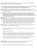
Information Guide. Recommended Tools The procedures in this document may require the following tools: q Small flat-blade screwdriver q Phillips screwdriver q Small plastic scribe q Flash BIOS update program floppy disk or CD Shutting Down Your Computer file:///F|/Service%20Manuals/Dell/Latitude/x300 - Dell Latitude X300 | Service Manual - Page 3
: Dell Latitude X300 Service Manual Use the following safety guidelines to help protect your computer from potential damage and to ensure your own personal safety. CAUTION: Before you begin any of the procedures in this section, follow the safety instructions in the System Information Guide. NOTICE - Dell Latitude X300 | Service Manual - Page 4
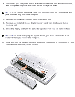
Before You Begin: Dell Latitude X300 Service Manual 6. Disconnect your computer and all attached devices from their electrical outlets, and then press the power button to ground the system board. NOTICE: To connect a network cable, first plug the cable into the network wall jack and then plug it - Dell Latitude X300 | Service Manual - Page 5
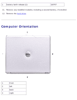
Begin: Dell Latitude X300 Service Manual 1 battery latch release (2) G0767 11. Remove any installed modules, including a second battery, if installed. 12. Remove the hard drive. Computer Orientation 1 front 2 left 3 back 4 right file:///F|/Service%20Manuals/Dell/Latitude/x300/before.htm - Dell Latitude X300 | Service Manual - Page 6
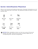
Before You Begin: Dell Latitude X300 Service Manual Screw Identification Placemat When you are removing and replacing components, photocopy the placemat as a tool to lay out and keep track of the screws. The placemat provides the number of screws and their sizes. - Dell Latitude X300 | Service Manual - Page 7
Before You Begin: Dell Latitude X300 Service Manual Keyboard: Palm Rest: (4 each) (9 each) Display Assembly: (2 each) Keyboard Tray: (5 each) Hard Drive: (4 each) System Board: (3 each) file:///F|/Service%20Manuals/Dell/Latitude/x300/before.htm (6 of 7) [2/28/2004 8:26:24 AM] - Dell Latitude X300 | Service Manual - Page 8
Before You Begin: Dell Latitude X300 Service Manual Modem Card: Cooling Fan: (1 each) (4 each) Speakers: (1 each) Bluetooth™ Module (1 each) Back to Contents Page file:///F|/Service%20Manuals/Dell/Latitude/x300/before.htm (7 of 7) [2/28/2004 8:26:24 AM] - Dell Latitude X300 | Service Manual - Page 9
Page Dell Diagnostics Dell™ Latitude™ X300 Service Manual When to Use the Dell Diagnostics Starting the Dell Diagnostics When to Use the Dell Diagnostics If you experience a problem with your computer, perform the checks in the "Solving Problems" section in your User's Guide or Owner's Manual and - Dell Latitude X300 | Service Manual - Page 10
board, keyboard, hard drive, and display. q During the assessment, answer any questions that appear. q If a failure is detected, the computer stops and beeps. To stop the assessment and restart the computer, press ; to continue to the next file:///F|/Service%20Manuals/Dell/Latitude/x300/diag.htm - Dell Latitude X300 | Service Manual - Page 11
an error code and a description of the problem. Write down the error code and problem description and follow the instructions on the screen. If you cannot resolve the error condition, contact Dell. See your User's Guide or file:///F|/Service%20Manuals/Dell/Latitude/x300/diag.htm (3 of 4) [2/28/2004 - Dell Latitude X300 | Service Manual - Page 12
Dell Diagnostics: Dell Latitude X300 Service Manual Owner's Manual for contact information. NOTE: The Service Tag for your computer is located at the top of each test screen. If you contact Dell, technical support will ask for your Service codes, and the problem description. Help Describes the - Dell Latitude X300 | Service Manual - Page 13
computer. Damage due to servicing that is not authorized by Dell is not covered by your warranty. NOTICE: Unless otherwise noted, each procedure in this manual assumes that a part can be replaced by performing the removal procedure in reverse order. file:///F|/Service%20Manuals/Dell/Latitude/x300 - Dell Latitude X300 | Service Manual - Page 14
Components: Dell Latitude X300 Service Manual 1 display 2 hinge covers (2) 3 keyboard tray 4 battery 5 cooling fan 6 hard drive 7 bottom case see Mini RSL M0270 D2589 see Mini RSL see Mini RSL 8 speakers (2) 9 reserve battery 10 Bluetooth™ module 11 system board 12 palm rest 13 keyboard 7C552 - Dell Latitude X300 | Service Manual - Page 15
connected to a media base (docked), undock it. See the documentation that came with your media base for instructions. 3. Slide the battery latch releases on the bottom of the computer and remove the battery from the bay. file:///F|/Service%20Manuals/Dell/Latitude/x300/battery.htm (1 of 3) [2/28/2004 - Dell Latitude X300 | Service Manual - Page 16
Battery: Dell Latitude X300 Service Manual 1 battery latch release (2) G0767 Installing the Battery To install the battery, slide the battery or the optional extended battery into the bay until the latch release clicks. file:///F|/Service%20Manuals/Dell/Latitude/x300/battery.htm (2 of 3) [2/28/ - Dell Latitude X300 | Service Manual - Page 17
Battery: Dell Latitude X300 Service Manual 1 optional extended battery Back to Contents Page Y0037 file:///F|/Service%20Manuals/Dell/Latitude/x300/battery.htm (3 of 3) [2/28/2004 8:26:26 AM] - Dell Latitude X300 | Service Manual - Page 18
came with your media base for instructions. 4. Disconnect the computer from the electrical outlet. 5. Wait 10 to 20 seconds, and then disconnect any attached devices. 6. Remove any installed PC Cards and battery. file:///F|/Service%20Manuals/Dell/Latitude/x300/upgrades.htm (1 of 14) [2/28/2004 8:26 - Dell Latitude X300 | Service Manual - Page 19
Memory, Modem, and Mini PCI Card Modules: Dell Latitude X300 Service Manual NOTICE: Handle components and cards by their edges, and avoid touching pins and contacts. Ground yourself by touching a metal connector on the back of the computer. Continue to ground yourself periodically during this - Dell Latitude X300 | Service Manual - Page 20
PCI Card Modules: Dell Latitude X300 Service Manual 8. If you are replacing a memory module, remove the existing module. NOTICE: Handle components and cards by their edges, and avoid touching pins and contacts. Ground yourself by touching a metal connector on the back of the computer. Continue to - Dell Latitude X300 | Service Manual - Page 21
and reinstall it. NOTE: If the memory module is not installed properly, the computer may not boot properly. No error message indicates this failure. 1 memory module 2 connector see Mini RSL 10. Replace the cover. file:///F|/Service%20Manuals/Dell/Latitude/x300/upgrades.htm (4 of 14) [2/28/2004 - Dell Latitude X300 | Service Manual - Page 22
into the battery bay, or connect the AC adapter to your computer and an electrical outlet. 12. Turn on the computer. As the computer boots, it detects the additional memory and automatically updates the system configuration information. file:///F|/Service%20Manuals/Dell/Latitude/x300/upgrades.htm - Dell Latitude X300 | Service Manual - Page 23
Modem, and Mini PCI Card Modules: Dell Latitude X300 Service Manual To confirm the amount of memory installed in the computer: q In the Microsoft® Windows® XP operating system, click the Start button, click Help and Support, and then click Computer Information. q In Windows 2000, right-click the My - Dell Latitude X300 | Service Manual - Page 24
Memory, Modem, and Mini PCI Card Modules: Dell Latitude X300 Service Manual 1 captive screw (2) 2 cover 8. If a modem is not already installed, go to step 10. 9. If you are replacing a modem, remove the existing modem: a. Remove the screw securing the modem to the system board, and set it aside. b. - Dell Latitude X300 | Service Manual - Page 25
Memory, Modem, and Mini PCI Card Modules: Dell Latitude X300 Service Manual 1 modem cable connector 2 modem 3 modem screw 4 system board connector 10. screw to secure the modem to the system board. file:///F|/Service%20Manuals/Dell/Latitude/x300/upgrades.htm (8 of 14) [2/28/2004 8:26:29 AM] - Dell Latitude X300 | Service Manual - Page 26
: Dell Latitude X300 Service Manual 13. Replace the cover. Adding a Mini PCI Card If you ordered a Mini PCI card with your computer, the card is already installed. CAUTION: Before performing any of the procedures listed below, read and follow the safety instructions in the System Information Guide - Dell Latitude X300 | Service Manual - Page 27
X300 Service Manual 1 captive screw (2) 2 cover 8. If a Mini PCI card is not already installed, go to step 10. 9. If you are replacing a Mini PCI card, remove the existing card: a. Disconnect the Mini PCI card from the attached cables. file:///F|/Service%20Manuals/Dell/Latitude/x300/upgrades - Dell Latitude X300 | Service Manual - Page 28
Memory, Modem, and Mini PCI Card Modules: Dell Latitude X300 Service Manual 1 cable connectors b. Release the Mini PCI card by spreading the metal securing tabs until the card pops up slightly. file:///F|/Service%20Manuals/Dell/Latitude/x300/upgrades.htm (11 of 14) [2/28/2004 8:26:29 AM] - Dell Latitude X300 | Service Manual - Page 29
Memory, Modem, and Mini PCI Card Modules: Dell Latitude X300 Service Manual 1 latch releases 2 MPCI card c. Lift the Mini PCI card out of its connector. NOTICE: To avoid damaging the Mini PCI card, never place cables on top of or under the card. 10. To replace a Mini PCI card, align the card - Dell Latitude X300 | Service Manual - Page 30
Memory, Modem, and Mini PCI Card Modules: Dell Latitude X300 Service Manual 1 connector 2 Mini PCI card N0498 13. Connect the antenna cable feel resistance, check the connectors and realign the card. file:///F|/Service%20Manuals/Dell/Latitude/x300/upgrades.htm (13 of 14) [2/28/2004 8:26:29 AM] - Dell Latitude X300 | Service Manual - Page 31
Memory, Modem, and Mini PCI Card Modules: Dell Latitude X300 Service Manual 1 cable connector 14. Replace the cover and tighten the screws. Back to Contents Page file:///F|/Service%20Manuals/Dell/Latitude/x300/upgrades.htm (14 of 14) [2/28/2004 8:26:29 AM] - Dell Latitude X300 | Service Manual - Page 32
to Contents Page Keyboard Dell™ Latitude™ X300 Service Manual Removing the Keyboard Replacing the Keyboard Removing the Keyboard CAUTION: Before you begin any of the procedures in this section, follow the safety instructions in the System Information Guide. NOTICE: Disconnect the computer and any - Dell Latitude X300 | Service Manual - Page 33
dislodged, and timeconsuming to replace. Be careful when removing and handling the keyboard. 3. Turn the computer over, and insert a ¼-inch flat-blade screwdriver into the slot to the right of the keyboard locator tab. file:///F|/Service%20Manuals/Dell/Latitude/x300/keyboard.htm (2 of 6) [2/28/2004 - Dell Latitude X300 | Service Manual - Page 34
Keyboard: Dell Latitude X300 Service Manual 1 keyboard locator tab 4. Pry up the keyboard locator tab, and the keyboard pops up. 5. Pull the keyboard a small distance toward the front of the computer to release the four securing tabs located across the back edge of the keyboard. 6. Rotate the - Dell Latitude X300 | Service Manual - Page 35
Keyboard: Dell Latitude X300 Service Manual 1 ZIF connector 2 keyboard flex cable 3 ZIF connector tabs (2) 8. Remove the keyboard flex cable from the ZIF connector. 9. Lift the keyboard up and out of the computer. Replacing the Keyboard file:///F|/Service%20Manuals/Dell/Latitude/x300/keyboard.htm (4 - Dell Latitude X300 | Service Manual - Page 36
Keyboard: Dell Latitude X300 Service Manual 1. Place the keyboard face-down on the palm rest, with the keyboard flex cable pointing toward the back of the computer. NOTICE: To avoid damage to the connector pins, insert the keyboard flex cable evenly into the ZIF connector on the system board, and do - Dell Latitude X300 | Service Manual - Page 37
Keyboard: Dell Latitude X300 Service Manual file:///F|/Service%20Manuals/Dell/Latitude/x300/keyboard.htm (6 of 6) [2/28/2004 8:26:30 AM] - Dell Latitude X300 | Service Manual - Page 38
Page Palm Rest Dell™ Latitude™ X300 Service Manual Removing the Palm Rest Replacing the Palm Rest Removing the Palm Rest CAUTION: Before you begin any of the procedures in this section, follow the safety instructions in the System Information Guide. NOTICE: Disconnect the computer and any attached - Dell Latitude X300 | Service Manual - Page 39
Palm Rest: Dell Latitude X300 Service Manual 1 M2 x 4-mm screws (3) 98MKC 4. Turn the computer over, and open the display. 5. Remove the six M2 x 4-mm screws on the palm rest. file:///F|/Service%20Manuals/Dell/Latitude/x300/palmrest.htm (2 of 5) [2/28/2004 8:26:31 AM] - Dell Latitude X300 | Service Manual - Page 40
Palm Rest: Dell Latitude X300 Service Manual 1 M2 x 4-mm screws (6) 98MKC 6. Lift up and rotate the palm rest forward. 7. Lift the ZIF connector, and disconnect the palm-rest flex cable from its ZIF connector on the system board. file:///F|/Service%20Manuals/Dell/Latitude/x300/palmrest.htm (3 of - Dell Latitude X300 | Service Manual - Page 41
Rest: Dell Latitude X300 Service Manual 1 palm-rest flex cable 2 ZIF connector 3 palm rest 8. Lift the palm rest up and out of the computer. Replacing the Palm Rest To aid with proper flex cable connection, a locator line has been added near the end of the palm-rest flex cable. When replacing the - Dell Latitude X300 | Service Manual - Page 42
Palm Rest: Dell Latitude X300 Service Manual closed, which should not indicate a problem with the connection.) Back to Contents Page file:///F|/Service%20Manuals/Dell/Latitude/x300/palmrest.htm (5 of 5) [2/28/2004 8:26:31 AM] - Dell Latitude X300 | Service Manual - Page 43
Contents Page Hard Drive Dell™ Latitude™ X300 Service Manual Removing the Hard Drive Replacing the Hard Drive Removing the Hard Drive CAUTION: Before you begin any of the procedures in this section, follow the safety instructions in the System Information Guide. NOTICE: Disconnect the computer and - Dell Latitude X300 | Service Manual - Page 44
Hard Drive: Dell Latitude X300 Service Manual 1 hard drive connector 2 hard drive 3 M2 x 5.5-mm screws (4) see Mini RSL 6K709 5. Disconnect the hard drive connector from the system board. 6. Lift the hard drive up and out of the bottom case. Replacing the Hard Drive file:///F|/Service%20Manuals/ - Dell Latitude X300 | Service Manual - Page 45
Hard Drive: Dell Latitude X300 Service Manual 1. Connect the hard drive connector to the system board. 2. Position the hard drive on the bottom case and tighten the four M2 x 5.5-mm screws to the bottom case. NOTE: The rubber grommets help you avoid overtightening the screws. - Dell Latitude X300 | Service Manual - Page 46
in this section, follow the safety instructions in the System Information Guide. 1. Remove the battery. 2. On the inside of the battery bay, use your fingers to unhook the hinge covers from the back of the computer. file:///F|/Service%20Manuals/Dell/Latitude/x300/display.htm (1 of 7) [2/28/2004 8:26 - Dell Latitude X300 | Service Manual - Page 47
hinge cover fits over the power button. Both hinge covers pass through the display hinges to the back of the computer. b. Ensure that the two securing tabs on the outer edge of each hinge cover are engaged in their respective slots. file:///F|/Service%20Manuals/Dell/Latitude/x300/display.htm (2 of - Dell Latitude X300 | Service Manual - Page 48
Read "Before You Begin" before performing the following procedure. 1. Remove the battery. 2. Remove the keyboard. 3. Turn the computer over, and remove the two M3 x 5-mm screws from the bottom of the computer. file:///F|/Service%20Manuals/Dell/Latitude/x300/display.htm (3 of 7) [2/28/2004 8:26:33 AM - Dell Latitude X300 | Service Manual - Page 49
Hinge Covers and Display Assembly: Dell Latitude X300 Service Manual 1 M3 x 5-mm screws (2) 7T775 4. Turn the computer over and open the display 180 degrees. file:///F|/Service%20Manuals/Dell/Latitude/x300/display.htm (4 of 7) [2/28/2004 8:26:33 AM] - Dell Latitude X300 | Service Manual - Page 50
Hinge Covers and Display Assembly: Dell Latitude X300 Service Manual 1 M2 x 6-mm screws (2) 8T707 5. Remove the two M2 x 6-mm screws near the display hinges on the top of the computer. 6. Disconnect both the antenna connectors. NOTICE: Do not pull on the signal cable. Pull the signal connector - Dell Latitude X300 | Service Manual - Page 51
out of the bottom case. Replacing the Display 1. Replace the display assembly into the bottom case and open the display 180 degrees. 2. Replace the two M2 x 6-mm screws by the display hinges on the top of the computer. file:///F|/Service%20Manuals/Dell/Latitude/x300/display.htm (6 of 7) [2/28/2004 - Dell Latitude X300 | Service Manual - Page 52
to the system board. 6. Close the display and turn the computer over. 7. Replace the two M3 x 5-mm screws from the bottom of the computer. 8. Replace the keyboard. 9. Replace the battery. Back to Contents Page file:///F|/Service%20Manuals/Dell/Latitude/x300/display.htm (7 of 7) [2/28/2004 8:26:33 AM - Dell Latitude X300 | Service Manual - Page 53
Page Keyboard Tray Dell™ Latitude™ X300 Service Manual Removing the Keyboard Tray Replacing the Keyboard Tray Removing the Keyboard Tray CAUTION: Before you begin any of the procedures in this section, follow the safety instructions in the System Information Guide. NOTICE: Disconnect the computer - Dell Latitude X300 | Service Manual - Page 54
Keyboard Tray: Dell Latitude X300 Service Manual 1 keyboard tray 2 M2 x 4-mm screws (5) 98MKC 7. Lift the keyboard tray up and slip out the antenna cables before lifting the tray out of the bottom case. Replacing the Keyboard Tray 1. Replace the keyboard tray. 2. Route the antenna cables through - Dell Latitude X300 | Service Manual - Page 55
Keyboard Tray: Dell Latitude X300 Service Manual 1 antenna cable connectors 2 oval opening on keyboard tray 3. Reinstall the five M2 x 4-mm screws that secure the keyboard tray to the system board. Back to Contents Page file:///F|/Service%20Manuals/Dell/Latitude/x300/keytray.htm (3 of 3) [2/28/2004 - Dell Latitude X300 | Service Manual - Page 56
Reserve Battery Dell™ Latitude™ X300 Service Manual Removing the Reserve Battery Replacing the Reserve Battery Removing the Reserve Battery CAUTION: Before you begin any of the procedures in this section, follow the safety instructions in the System Information Guide. NOTICE: Disconnect the computer - Dell Latitude X300 | Service Manual - Page 57
Reserve Battery: Dell Latitude X300 Service Manual 1 reserve battery 2 reserve battery cable 3 reserve battery connector 4 system board connector W2662 5. Disconnect the speaker cables. 6. Pry the reserve battery free from the bottom case. The reserve battery is attached to the bottom case with a - Dell Latitude X300 | Service Manual - Page 58
Reserve Battery: Dell Latitude X300 Service Manual Replacing the Reserve Battery 1. Connect the reserve battery connector to the system board connector. 2. Press the reserve battery into place on the bottom case. 3. Ensure that the cable is routed correctly as shown to avoid damaging the cable. 1 - Dell Latitude X300 | Service Manual - Page 59
Reserve Battery: Dell Latitude X300 Service Manual 1 speaker cables 2 speakers 5. Update the CMOS settings. see Mini RSL Back to Contents Page file:///F|/Service%20Manuals/Dell/Latitude/x300/rsrvbatt.htm (4 of 4) [2/28/2004 8:26:35 AM] - Dell Latitude X300 | Service Manual - Page 60
Speakers: Dell Latitude X300 Service Manual Back to Contents Page Speakers Dell™ Latitude™ X300 Service Manual Removing the Speakers CAUTION: Before you begin any of the procedures in this section, follow the safety instructions in the System Information Guide. NOTICE: Disconnect the computer and - Dell Latitude X300 | Service Manual - Page 61
Speakers: Dell Latitude X300 Service Manual 1 system board connector (1 per speaker) 2 speaker connector (1 per speaker) 3 M2 x 4-mm screw (1 per speaker) 4 speaker cable (1 per speaker) 5 speakers (2) 98MKC see Mini RSL NOTICE: Do - Dell Latitude X300 | Service Manual - Page 62
Speakers: Dell Latitude X300 Service Manual Back to Contents Page file:///F|/Service%20Manuals/Dell/Latitude/x300/speakers.htm (3 of 3) [2/28/2004 8:26:35 AM] - Dell Latitude X300 | Service Manual - Page 63
™ Module: Dell Latitude X300 Service Manual Back to Contents Page Bluetooth™ Module Dell™ Latitude™ X300 Service Manual Replacing the Bluetooth Module CAUTION: Before you begin any of the procedures in this section, follow the safety instructions in the System Information Guide. 1. Remove the M2 - Dell Latitude X300 | Service Manual - Page 64
Dell Latitude X300 Service Manual 1 M2 x 5-mm screw 2 Bluetooth module 3 Bluetooth module cable 4 connector on system board 4. To replace the Bluetooth module: a. Replace the assembly. b. Connect the cable to the system board. c. Replace the screw. 2U381 file:///F|/Service%20Manuals/Dell/Latitude - Dell Latitude X300 | Service Manual - Page 65
Bluetooth™ Module: Dell Latitude X300 Service Manual Back to Contents Page file:///F|/Service%20Manuals/Dell/Latitude/x300/bluetoot.htm (3 of 3) [2/28/2004 8:26:36 AM] - Dell Latitude X300 | Service Manual - Page 66
Fan: Dell Latitude X300 Service Manual Back to Contents Page Cooling Fan Dell™ Latitude™ X300 Service Manual Removing the Cooling Fan CAUTION: Before you begin any of the procedures in this section, follow the safety instructions in the System Information Guide. NOTICE: Disconnect the computer - Dell Latitude X300 | Service Manual - Page 67
Fan: Dell Latitude X300 Service Manual 1 M2 x 3-mm screws (4) 2 cooling fan 3 cooling fan cable 4 cooling fan connector 5 system board connector 2013T D2589 5. Remove the tape that secures the cooling fan cable to the fan. NOTICE: Do not pull on the cooling fan cable. Pull from the cooling fan - Dell Latitude X300 | Service Manual - Page 68
Cooling Fan: Dell Latitude X300 Service Manual 6. Disconnect the cooling fan cable from the system board connector. 7. Lift the cooling fan up and out of the bottom case. Back to Contents Page file:///F|/Service%20Manuals/Dell/Latitude/x300/fan.htm (3 of 3) [2/28/2004 8:26:37 AM] - Dell Latitude X300 | Service Manual - Page 69
the battery. 2. Remove the keyboard. 3. Remove the palm rest. 4. Remove the hinge covers. 5. Remove the display assembly. 6. Remove the keyboard tray. 7. Remove the hard drive. 8. Remove the memory module. 9. Remove the Mini PCI card, if present. file:///F|/Service%20Manuals/Dell/Latitude/x300 - Dell Latitude X300 | Service Manual - Page 70
: Dell Latitude X300 Service Manual 10. Remove the modem card, if present. 11. Remove the system board. 12. On the inside of the bottom case, use your fingers to unhook the latch from the bottom case and the snap tabs, catching the latch button on the outside of the bottom case. 1 spring 2 battery - Dell Latitude X300 | Service Manual - Page 71
Battery Latches: Dell Latitude X300 Service Manual 5 spring 6 battery-latch release button Replacing the Battery Latches 1. Snap in the new latch button from behind the bottom case, making certain that the snap tabs are fully engaged in the latch. NOTE: The battery latch release has springs and - Dell Latitude X300 | Service Manual - Page 72
the battery. 2. Remove the keyboard. 3. Remove the palm rest. 4. Remove the hinge covers. 5. Remove the display assembly. 6. Remove the keyboard tray. 7. Remove the hard drive. 8. Remove the memory module. 9. Remove the Mini PCI card, if present. file:///F|/Service%20Manuals/Dell/Latitude/x300 - Dell Latitude X300 | Service Manual - Page 73
System Board: Dell Latitude X300 Service Manual 10. Remove the modem card, if present. 11. Remove the three M2 x 4-mm screws that secure the system board to the bottom case. NOTE: Each system board screw has an arrow beside it. 1 system - Dell Latitude X300 | Service Manual - Page 74
System Board: Dell Latitude X300 Service Manual 4 ZIF connector 12. Disconnect the left and right speakers from their system board connectors. 13. Disconnect the reserve battery connector from the system board connector. 14. Disconnect the Bluetooth cable from the system board, if a Bluetooth™ - Dell Latitude X300 | Service Manual - Page 75
: Dell Latitude X300 Service Manual 1 wireless antenna 2. Reconnect all the cables to the system board ZIF connectors. 3. Reinstall the three M2 x 4-mm screws that secure the system board to the bottom case. NOTE: After replacing the system board, enter the computer Service Tag into the BIOS of - Dell Latitude X300 | Service Manual - Page 76
operating system and language for your computer. 5. Select the FlashBIOS Updates download category. Click Go. 6. Click the BIOS link and follow the instructions to download the BIOS to your computer. Back to Contents Page file:///F|/Service%20Manuals/Dell/Latitude/x300/bios.htm [2/28/2004 8:26:39 AM - Dell Latitude X300 | Service Manual - Page 77
Pin Assignments for I/O Connectors: Dell Latitude X300 Service Manual Back to Contents Page Pin Assignments for I/O Connectors Dell™ Latitude™ X300 Service Manual Pin Assignments for the Computer Pin Assignments for the Media Base Pin Assignments for the Computer USB Connector 2.0 Pin Signal 1 - Dell Latitude X300 | Service Manual - Page 78
: Dell Latitude X300 Service Manual Pin Signal 1 RED 2 GREEN 3 BLUE 4 NC 5 GND 6 GND 7 GND 8 GND Pin Signal 9 CRT_VCC 10 GND 11 NC 12 DAT_DDC2 13 HSYNC 14 VSYNC 15 CLK_DDC2 IEEE 1394 Connector 1 TPB- 2 TPB+ 3 TPA- 4 TPA+ file:///F|/Service%20Manuals/Dell - Dell Latitude X300 | Service Manual - Page 79
Pin Assignments for I/O Connectors: Dell Latitude X300 Service Manual Dell D/Bay Connector Pin Signal 1 USB_VCC 2 USB_D- 3 USB_D+ 4 USB_GND 5 PWR_SRC Pin Signal 6 SMB_DAT 7 MODPRES# 8 SMB_CLK 9 GND Pin Assignments for the Media Base Docking Connector Pin Signal Pin Signal - Dell Latitude X300 | Service Manual - Page 80
Pin Assignments for I/O Connectors: Dell Latitude X300 Service Manual 1 DCK3_DOCK_IN2* 3 SYS_DCIN* 5 VDC 7 VDC 9 VDC 11 KBC3_ADID_CLK 13 GND 15 PIO3_SLCT 17 PIO3_AUTOFD* 19 PIO3_ERROR* 21 PIO3_INIT* 23 PIO3_SLCTIN* 25 GND 27 PIO3_PD0 29 PIO3_PD1 - Dell Latitude X300 | Service Manual - Page 81
Pin Assignments for I/O Connectors: Dell Latitude X300 Service Manual 55 SIO3_TXD1* 57 SIO3_RTS1* 59 SIO3_CTS1* 61 SIO3_R11* 63 USB3_P494 MOD_PRES* 96 1394_TPA98 1394_TPA+ 100 DCK3_DOCK_IN1* PS/2 Connector file:///F|/Service%20Manuals/Dell/Latitude/x300/pinouts.htm (5 of 9) [2/28/2004 8:26:40 AM] - Dell Latitude X300 | Service Manual - Page 82
Pin Assignments for I/O Connectors: Dell Latitude X300 Service Manual Pin Signal 1 DAT_KBD 2 DAT_SM1 3 GND 4 PS2VCC 5 CLK_KBD 6 CLK_SM1 Parallel Connector Pin Signal 1 STRB*/5V 2 PD0/INDEX* 3 PD1/TRK0* 4 PD2/WP* 5 PD3/RDATA* Pin Signal 10 - Dell Latitude X300 | Service Manual - Page 83
Pin Assignments for I/O Connectors: Dell Latitude X300 Service Manual 6 PD4/DSKCHG* 7 PD5F 8 PD6F 9 PD7F 15 16 17 18-25 15 8 GND Serial Connector Signal CRT_VCC GND NC DAT_DDC2 HSYNC VSYNC CLK_DDC2 file:///F|/Service%20Manuals/Dell/Latitude/x300/pinouts.htm (7 of 9) [2/28/2004 8:26:40 AM] - Dell Latitude X300 | Service Manual - Page 84
for I/O Connectors: Dell Latitude X300 Service Manual Pin Signal Pin Signal 1 DCD* 2 RXDA 3 TXDA 4 DTR* 5 GND 6 DSR* 7 RTS* 8 CTS* 9 RI* IEEE 1394 Connector 1 TPB- 2 TPB+ 3 TPA- 4 TPA+ USB Connector 2.0 (2) file:///F|/Service%20Manuals/Dell/Latitude/x300/pinouts.htm - Dell Latitude X300 | Service Manual - Page 85
Pin Assignments for I/O Connectors: Dell Latitude X300 Service Manual Pin Signal 1 VCC 2 Data- 3 Data+ 4 GND Back to Contents Page file:///F|/Service%20Manuals/Dell/Latitude/x300/pinouts.htm (9 of 9) [2/28/2004 8:26:40 AM] - Dell Latitude X300 | Service Manual - Page 86
Dell™ Latitude™ X300 Service Manual NOTE: The part numbers listed below are subject to change. Bottom Plastics Assembly G0767 H0163 H0164 T2913 U2737 battery latch kit bottom LCD-cover assembly memory door bottom plastics assembly (TAA-compliant) bottom plastics assembly (non-TAA version) Power - Dell Latitude X300 | Service Manual - Page 87
24X CD-RW/DVD Combo Floppy Drive 1R159 floppy drive, D-module Hard Drive and Accessories N2902 N2903 U2407 T2445 20-G HDD 30-G HDD 40-G HDD (5400 RPM) 60-G HDD (5400 RPM) Fan D2589 fan Keyboard 5Y730 keyboard, US file:///F|/Service%20Manuals/Dell/Latitude/x300/minirsl.htm (2 of 4) [2/28 - Dell Latitude X300 | Service Manual - Page 88
Mini Recommended Spares List: Dell Latitude X300 Service Manual Hinges G0810 H0192 J0045 left hinge cover right hinge cover 12.1 LCD hinge up assembly Memory 3Y180 3Y182 0K963 7N020 128-MB DIMM 256-MB DIMM 512-MB DIMM 1-G DIMM Modem Y0231 56-K V2 internal modem System Board T2907 U2733 - Dell Latitude X300 | Service Manual - Page 89
Mini Recommended Spares List: Dell Latitude X300 Service Manual J0846 N0498 TM1300, 802.11b/g Intel 2.4 GHz Screws 2013T 6K709 6R788 7T775 Rest Assembly G0808 palm rest assembly Back to Contents Page file:///F|/Service%20Manuals/Dell/Latitude/x300/minirsl.htm (4 of 4) [2/28/2004 8:26:41 AM]
-
 1
1 -
 2
2 -
 3
3 -
 4
4 -
 5
5 -
 6
6 -
 7
7 -
8
-
9
-
10
-
11
-
12
-
13
-
14
-
15
-
16
-
17
-
18
-
19
-
20
-
21
-
22
-
23
-
24
-
25
-
26
-
27
-
28
-
29
-
30
-
31
-
32
-
33
-
34
-
35
-
36
-
37
-
38
-
39
-
40
-
41
-
42
-
43
-
44
-
45
-
46
-
47
-
48
-
49
-
50
-
51
-
52
-
53
-
54
-
55
-
56
-
57
-
58
-
59
-
60
-
61
-
62
-
63
-
64
-
65
-
66
-
67
-
68
-
69
-
70
-
71
-
72
-
73
-
74
-
75
-
76
-
77
-
78
-
79
-
80
-
81
-
82
-
83
-
84
-
85
-
86
-
87
-
88
-
89
 |
 |

Dell Latitude X300 Service Manual
Dell™ Latitude™ X300 Service Manual
Before You Begin
Dell Diagnostics
System Components
Battery
Memory, Modem, and Mini PCI Card Modules
Keyboard
Palm Rest
Hard Drive
Hinge Covers and Display Assembly
Keyboard Tray
Reserve Battery
Speakers
Bluetooth™ Module
Cooling Fan
Battery Latches
System Board
Flashing the BIOS
Pin Assignments for I/O Connectors
Mini Recommended Spares List
Notes, Notices, and Cautions
NOTE:
A NOTE indicates important information that helps you make better use
of your computer.
NOTICE:
A NOTICE indicates either potential damage to hardware or loss of
data and tells you how to avoid the problem.
CAUTION:
A CAUTION indicates a potential for property damage,
personal injury, or death.
Information in this document is subject to change without notice.
file:///F|/Service%20Manuals/Dell/Latitude/x300/index.htm (1 of 2) [2/28/2004 8:26:18 AM]