Dell OptiPlex 755 Quick Reference Guide - Page 53
to the VGA connector on the adapter., If you have a VGA monitor
 |
View all Dell OptiPlex 755 manuals
Add to My Manuals
Save this manual to your list of manuals |
Page 53 highlights
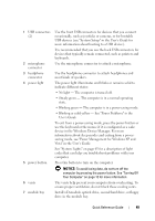
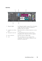
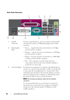
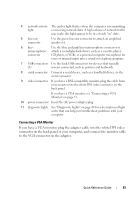
4 network activity The amber light flashes when the computer is transmitting light or receiving network data. A high volume of network traffic may make this light appear to be in a steady "on" state. 5 line-out connector Use the green line-out connector to attach an amplified speaker set. 6 line- Use the blue and pink line-in/microphone connector to in/microphone attach a record/playback device such as a cassette player, connector CD player, or VCR.; or a personal computer microphone for voice or musical input into a sound or telephony program. 7 USB connectors Use the back USB connectors for devices that typically (5) remain connected, such as printers and keyboards. 8 serial connector Connect a serial device, such as a handheld device, to the serial connector. 9 video connector If you have a DVI-compatible monitor, plug the cable from your monitor into the white DVI video connector on the back panel. If you have a VGA monitor, see "Connecting a VGA Monitor" on page 53. 10 power connector Insert the AC power adapter plug. 11 diagnostic lights See "Diagnostic Lights" on page 66 for a description of light codes that can help you troubleshoot problems with your computer. Connecting a VGA Monitor If you have a VGA monitor, plug the adapter cable into the white DVI video connector on the back panel of your computer, and connect the monitor cable to the VGA connector on the adapter. Quick Reference Guide 53
-
 1
1 -
2
-
3
-
4
-
5
-
6
-
7
-
8
-
9
-
10
-
11
-
12
-
13
-
14
-
15
-
16
-
17
-
18
-
19
-
20
-
21
-
22
-
23
-
24
-
25
-
26
-
27
-
28
-
29
-
30
-
31
-
32
-
33
-
34
-
35
-
36
-
37
-
38
-
39
-
40
-
41
-
42
-
43
-
44
-
45
-
46
-
47
-
 48
48 -
 49
49 -
 50
50 -
 51
51 -
 52
52 -
 53
53 -
 54
54 -
 55
55 -
 56
56 -
 57
57 -
 58
58 -
59
-
60
-
61
-
62
-
63
-
64
-
65
-
66
-
67
-
68
-
69
-
70
-
71
-
72
-
73
-
74
-
75
-
76
-
77
-
78
-
79
-
80
-
81
-
82
-
83
-
84
-
85
-
86
-
87
-
88
-
89
-
90
-
91
-
92
-
93
-
94
-
95
-
96
-
97
-
98
-
99
-
100
-
101
-
102
-
103
-
104
-
105
-
106
-
107
-
108
-
109
-
110
-
111
-
112
-
113
-
114
-
115
-
116
-
117
-
118
-
119
-
120
-
121
-
122
-
123
-
124
-
125
-
126
-
127
-
128
-
129
-
130
-
131
-
132
-
133
-
134
-
135
-
136
-
137
-
138
-
139
-
140
-
141
-
142
-
143
-
144
-
145
-
146
-
147
-
148
-
149
-
150
-
151
-
152
-
153
-
154
-
155
-
156
-
157
-
158
-
159
-
160
-
161
-
162
-
163
-
164
-
165
-
166
-
167
-
168
-
169
-
170
-
171
-
172
-
173
-
174
-
175
-
176
-
177
-
178
-
179
-
180
-
181
-
182
-
183
-
184
-
185
-
186
-
187
-
188
-
189
-
190
-
191
-
192
-
193
-
194
-
195
-
196
-
197
-
198
-
199
-
200
-
201
-
202
-
203
-
204
-
205
-
206
-
207
-
208
-
209
-
210
-
211
-
212
-
213
-
214
-
215
-
216
-
217
-
218
-
219
-
220
-
221
-
222
-
223
-
224
-
225
-
226
-
227
-
228
-
229
-
230
-
231
-
232
-
233
-
234
-
235
-
236
-
237
-
238
-
239
-
240
-
241
-
242
-
243
-
244
-
245
-
246
-
247
-
248
-
249
-
250
-
251
-
252
-
253
-
254
-
255
-
256
-
257
-
258
-
259
-
260
-
261
-
262
-
263
-
264
-
265
-
266
 |
 |