Dell OptiPlex 755 Quick Reference Guide - Page 57
Cable Cover (Optional), Insert the tabs into the slots and slide the cover to align the ends of
 |
View all Dell OptiPlex 755 manuals
Add to My Manuals
Save this manual to your list of manuals |
Page 57 highlights
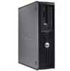
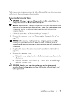
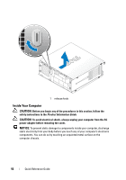
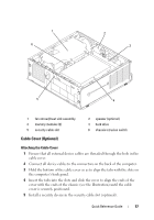
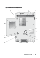
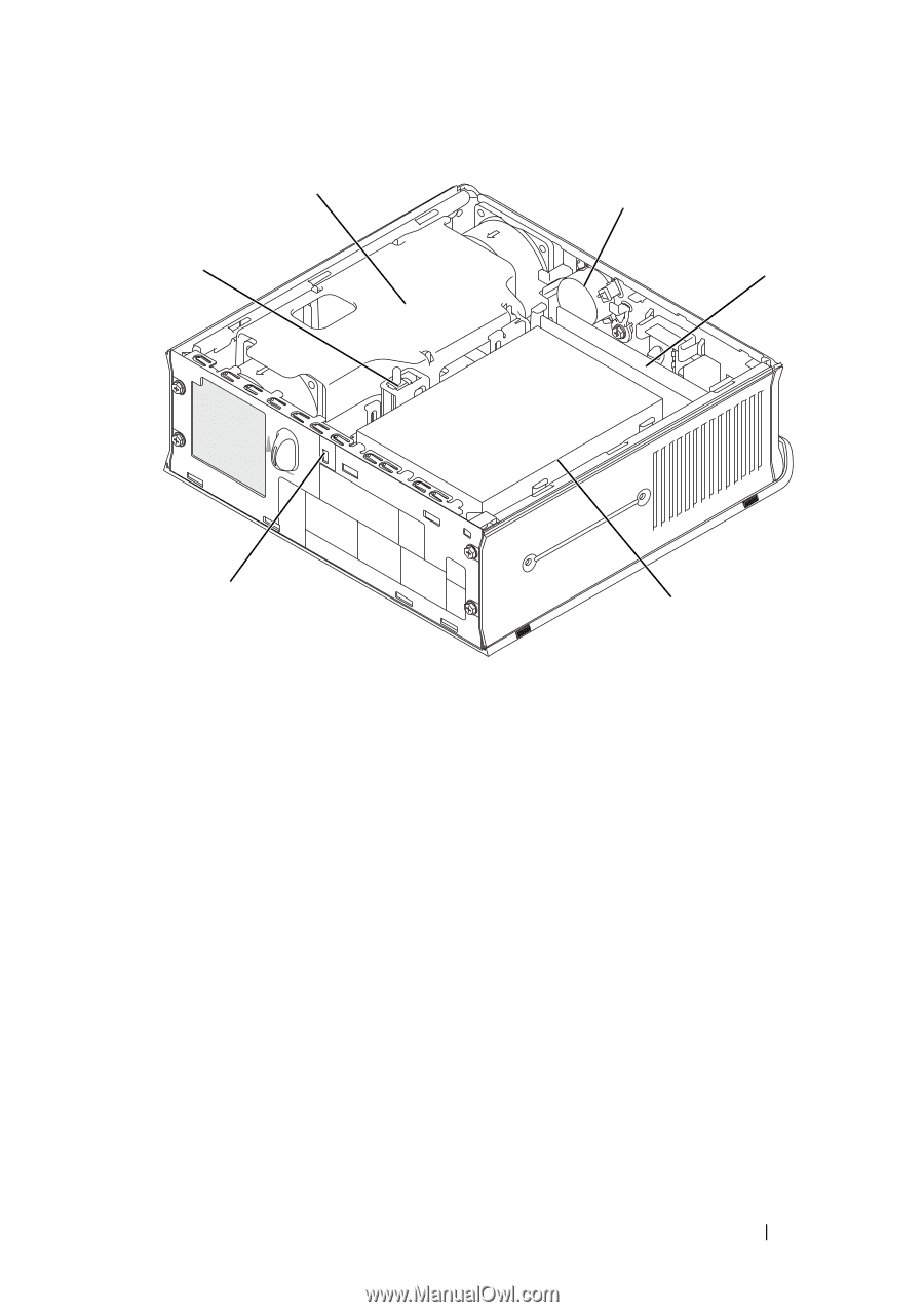
1 6 2 3 5 4 1 fan shroud/heat sink assembly 3 memory modules (2) 5 security cable slot 2 speaker (optional) 4 hard drive 6 chassis intrusion switch Cable Cover (Optional) Attaching the Cable Cover 1 Ensure that all external device cables are threaded through the hole in the cable cover. 2 Connect all device cables to the connectors on the back of the computer. 3 Hold the bottom of the cable cover so as to align the tabs with the slots on the computer's back panel. 4 Insert the tabs into the slots and slide the cover to align the ends of the cover with the ends of the chassis (see the illustration) until the cable cover is securely positioned. 5 Install a security device in the security cable slot (optional). Quick Reference Guide 57
-
 1
1 -
2
-
3
-
4
-
5
-
6
-
7
-
8
-
9
-
10
-
11
-
12
-
13
-
14
-
15
-
16
-
17
-
18
-
19
-
20
-
21
-
22
-
23
-
24
-
25
-
26
-
27
-
28
-
29
-
30
-
31
-
32
-
33
-
34
-
35
-
36
-
37
-
38
-
39
-
40
-
41
-
42
-
43
-
44
-
45
-
46
-
47
-
48
-
49
-
50
-
51
-
 52
52 -
 53
53 -
 54
54 -
 55
55 -
 56
56 -
 57
57 -
 58
58 -
 59
59 -
 60
60 -
 61
61 -
 62
62 -
63
-
64
-
65
-
66
-
67
-
68
-
69
-
70
-
71
-
72
-
73
-
74
-
75
-
76
-
77
-
78
-
79
-
80
-
81
-
82
-
83
-
84
-
85
-
86
-
87
-
88
-
89
-
90
-
91
-
92
-
93
-
94
-
95
-
96
-
97
-
98
-
99
-
100
-
101
-
102
-
103
-
104
-
105
-
106
-
107
-
108
-
109
-
110
-
111
-
112
-
113
-
114
-
115
-
116
-
117
-
118
-
119
-
120
-
121
-
122
-
123
-
124
-
125
-
126
-
127
-
128
-
129
-
130
-
131
-
132
-
133
-
134
-
135
-
136
-
137
-
138
-
139
-
140
-
141
-
142
-
143
-
144
-
145
-
146
-
147
-
148
-
149
-
150
-
151
-
152
-
153
-
154
-
155
-
156
-
157
-
158
-
159
-
160
-
161
-
162
-
163
-
164
-
165
-
166
-
167
-
168
-
169
-
170
-
171
-
172
-
173
-
174
-
175
-
176
-
177
-
178
-
179
-
180
-
181
-
182
-
183
-
184
-
185
-
186
-
187
-
188
-
189
-
190
-
191
-
192
-
193
-
194
-
195
-
196
-
197
-
198
-
199
-
200
-
201
-
202
-
203
-
204
-
205
-
206
-
207
-
208
-
209
-
210
-
211
-
212
-
213
-
214
-
215
-
216
-
217
-
218
-
219
-
220
-
221
-
222
-
223
-
224
-
225
-
226
-
227
-
228
-
229
-
230
-
231
-
232
-
233
-
234
-
235
-
236
-
237
-
238
-
239
-
240
-
241
-
242
-
243
-
244
-
245
-
246
-
247
-
248
-
249
-
250
-
251
-
252
-
253
-
254
-
255
-
256
-
257
-
258
-
259
-
260
-
261
-
262
-
263
-
264
-
265
-
266
 |
 |
Quick Reference Guide
57
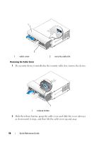
Cable Cover (Optional)
Attaching the Cable Cover
1
Ensure that all external device cables are threaded through the hole in the
cable cover.
2
Connect all device cables to the connectors on the back of the computer.
3
Hold the bottom of the cable cover so as to align the tabs with the slots on
the computer’s back panel.
4
Insert the tabs into the slots and slide the cover to align the ends of the
cover with the ends of the chassis (see the illustration) until the cable
cover is securely positioned.
5
Install a security device in the security cable slot (optional).
1
fan shroud/heat sink assembly
2
speaker (optional)
3
memory modules (2)
4
hard drive
5
security cable slot
6
chassis intrusion switch
1
2
4
6
3
5