Dell OptiPlex 9010 AIO Owner's Manual - Page 25
Installing the Input/Output Board Shield, Removing the Power-Button Board
 |
View all Dell OptiPlex 9010 AIO manuals
Add to My Manuals
Save this manual to your list of manuals |
Page 25 highlights
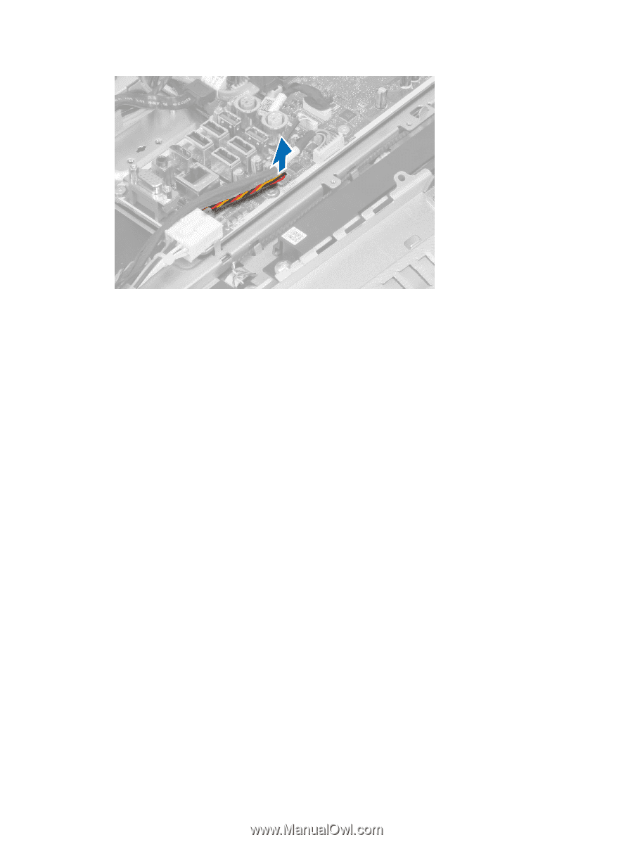
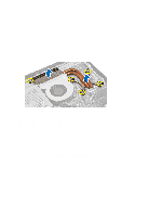
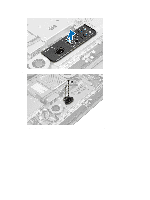
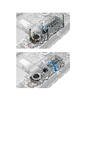
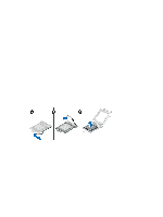
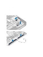
Installing the Input/Output Board Shield 1. Connect the power-connector cable. 2. Place the input/output board shield on the computer. 3. Pass the power connector and fix it to the socket. Tighten the screws to secure the input/output board shield to the chassis. 4. Tighten the screws that secure the power connector to the input/output shield. 5. Place the input/output panel on the computer. 6. Install: a) power-supply fan b) system-board shield c) VESA mount bracket d) back cover e) VESA stand 7. Follow the procedures in After Working Inside Your Computer. Removing the Power-Button Board 1. Follow the procedures in Before Working Inside Your Computer. 2. Remove the: a) VESA stand b) back cover 3. Disconnect the power-button cable from the board. Lift the power-button board from the chassis. 25
-
 1
1 -
2
-
3
-
4
-
5
-
6
-
7
-
8
-
9
-
10
-
11
-
12
-
13
-
14
-
15
-
16
-
17
-
18
-
19
-
 20
20 -
 21
21 -
 22
22 -
 23
23 -
 24
24 -
 25
25 -
 26
26 -
 27
27 -
 28
28 -
 29
29 -
 30
30 -
31
-
32
-
33
-
34
-
35
-
36
-
37
-
38
-
39
-
40
-
41
-
42
-
43
-
44
-
45
-
46
-
47
-
48
-
49
-
50
-
51
-
52
-
53
-
54
-
55
-
56
-
57
-
58
-
59
 |
 |