Dell OptiPlex 9010 AIO Owner's Manual - Page 31
Removing the Display Panel - disassembly
 |
View all Dell OptiPlex 9010 AIO manuals
Add to My Manuals
Save this manual to your list of manuals |
Page 31 highlights
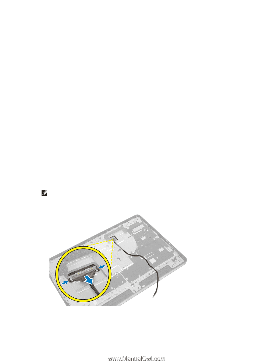
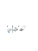
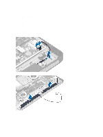
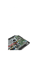
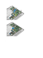
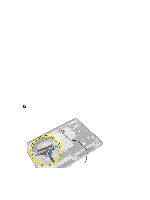
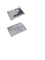
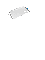
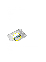
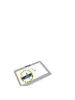
j) VESA mount bracket k) back cover l) VESA stand 4. Follow the procedures in After Working Inside Your Computer. Removing the Display Panel 1. Follow the procedures in Before Working Inside Your Computer. 2. Remove the: a) VESA stand b) back cover c) VESA mount bracket d) system-board shield e) input/output board shield f) WLAN card g) optical drive h) hard drive i) intrusion switch j) power-button board k) converter board l) power-supply fan m) power supply unit n) heat-sink assembly o) processor fan p) speakers q) antenna module r) system board NOTE: These instructions are valid only for non-touch computers. For touch computers, the display panel should be disassembled in a clean room environment. 3. Remove the LVDS cable by pressing the latch inwards and disconnecting it from the connector. Remove any other cables or antennas around the edges of the base panel. 4. Remove the screws that secure the base panel to the chassis. Lift the base panel from the chassis. 31
-
 1
1 -
2
-
3
-
4
-
5
-
6
-
7
-
8
-
9
-
10
-
11
-
12
-
13
-
14
-
15
-
16
-
17
-
18
-
19
-
20
-
21
-
22
-
23
-
24
-
25
-
 26
26 -
 27
27 -
 28
28 -
 29
29 -
 30
30 -
 31
31 -
 32
32 -
 33
33 -
 34
34 -
 35
35 -
 36
36 -
37
-
38
-
39
-
40
-
41
-
42
-
43
-
44
-
45
-
46
-
47
-
48
-
49
-
50
-
51
-
52
-
53
-
54
-
55
-
56
-
57
-
58
-
59
 |
 |