Dell OptiPlex 990 User Manual
Dell OptiPlex 990 Manual
 |
View all Dell OptiPlex 990 manuals
Add to My Manuals
Save this manual to your list of manuals |
Dell OptiPlex 990 manual content summary:
- Dell OptiPlex 990 | User Manual - Page 1
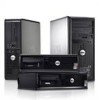
Dell OptiPlex 990 Setup And Features Information About Warnings WARNING: A WARNING indicates a potential for property damage, personal injury, or death. Mini Tower - Front And Back View Figure 1. Front And Back View Of Mini Tower 1. power button, power light 2. optical-drive bay (optional) 3. - Dell OptiPlex 990 | User Manual - Page 2
3. power button, power light 4. USB 2.0 connectors (4) 5. microphone connector 6. headphone connector 7. drive activity light 8. diagnostic lights (4) 9. padlock ring 10. security-cable slot 11. power connector 12. back panel connectors 13. expansion-card slots (4) 14. power supply diagnostic light - Dell OptiPlex 990 | User Manual - Page 3
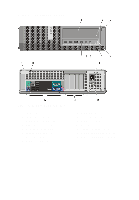
connectors (4) 5. microphone connector 6. headphone connector 7. diagnostic lights (4) 8. drive activity light 9. padlock ring 10. security-cable slot 11. power connector 12. power supply diagnostic button 13. power supply diagnostic light 14. back panel connectors 15. expansion-card slots (2) 3 - Dell OptiPlex 990 | User Manual - Page 4
drive 2. optical-drive eject button 3. power button, power light 4. drive activity light 5. diagnostic lights (4) 6. headphone connector light 11. captive thumbscrew 12. padlock ring 13. security-cable slot 14. power connector 15. line-out connector 16. line-in/microphone connector 17. DisplayPort - Dell OptiPlex 990 | User Manual - Page 5
Back Panel View of Mini Tower And Desktop 1. mouse connector 2. link integrity light 3. network connector 4. network activity light 5. serial connector 6. line-out connector Small Form Factor - Back Panel 7. keyboard connector 8. USB 2.0 connectors (6) 9. DisplayPort connector 10. VGA connector 11 - Dell OptiPlex 990 | User Manual - Page 6
. For additional best practices information, see www.dell.com/regulatory_compliance. NOTE: Some devices may not be included if you did not order them. 1. Connect the monitor using only one of the following cables: Figure 7. DVI Cable Figure 8. DisplayPort Cable Figure 9. VGA To DVI Adapter Figure - Dell OptiPlex 990 | User Manual - Page 7
Figure 11. VGA To DisplayPort Adapter 2. Connect the USB keyboard or mouse (optional). Figure 12. USB Connection 3. Connect the network cable (optional). Figure 13. Network Connection 4. Connect the modem (optional). Figure 14. Modem Connection 5. Connect the power cable(s). 7 - Dell OptiPlex 990 | User Manual - Page 8
Power 6. Press the power buttons on the monitor and the computer. Figure 16. Turning On Power Specifications NOTE: The following specifications are only those required by law to ship with your computer. For a complete and current listing of the specifications for your computer, go to support.dell - Dell OptiPlex 990 | User Manual - Page 9
Integrated video memory PCI Express x 16 graphics adapter up to 1.7 GB shared video memory (Microsoft Windows Vista and Windows 7) Memory Memory module connector: Desktop, Mini Tower, Small Form Factor Ultra Small Form Factor Memory module capacity Type Minimum memory Maximum memory: Desktop, Mini - Dell OptiPlex 990 | User Manual - Page 10
computer. For more information on the diagnostic lights, see the Service Manual at support.dell.com/ manuals. Back of computer Power supply light Green light - The power supply is turned on and is functional. The power cable must be connected to the power connector (at the back of the computer - Dell OptiPlex 990 | User Manual - Page 11
Tower - 1390 BTU/hr • Desktop - 1312 BTU/hr • Small Form Factor - 1259 BTU/hr • Ultra Small Form Factor - 758 BTU/hr NOTE: Heat dissipation is calculated by using the power supply wattage rating. NOTE: The voltage selector switch is available only on non-EPA power supplies. NOTE: See the safety - Dell OptiPlex 990 | User Manual - Page 12
Ultra Small Form Factor - 24.00 cm (9.45 inches) • Mini Tower - 8.87 kg (19.55 lb) • Desktop - 7.56 kg (16.67 lb) • Small Form Factor - 5.70 kg (12.57 lb) • Ultra Small Safety best practices • Regulatory certification • Ergonomics See www.dell.com for additional information on: • Warranty • Terms - Dell OptiPlex 990 | User Manual - Page 13
the Windows Vista start button, and Office Outlook® are either trademarks or registered trademarks of Microsoft Corporation in the United States and/or other countries. Blu-ray Disc™ is a trademark owned by the Blu-ray Disc Association (BDA) and licensed for use on discs and players. The Bluetooth
-
 1
1 -
 2
2 -
 3
3 -
 4
4 -
 5
5 -
 6
6 -
 7
7 -
8
-
9
-
10
-
11
-
12
-
13
 |
 |

Dell OptiPlex 990
Setup And Features Information
About Warnings
WARNING: A WARNING indicates a potential for property damage, personal injury,
or death.
Mini Tower — Front And Back View
Figure 1. Front And Back View Of Mini Tower
1.
power button, power light
2.
optical-drive bay (optional)
3.
headphone connector
4.
microphone connector
5.
diagnostic lights (4)
6.
optical drive (optional)
7.
optical-drive eject button
8.
USB 2.0 connectors (4)
9.
drive activity light
10.
power supply diagnostic light
11.
power supply diagnostic button
12.
power connector
13.
back panel connectors
14.
expansion-card slots (4)
15.
security-cable slot
16.
padlock ring
Regulatory Model: D09M, D05D, D03S, D01U
Regulatory Type: D09M001, D05D001,
D03S001, D01U002
January 2011