Dell PowerConnect 2848 User's Guide - Page 19
An RJ-45 connection for Twisted Pair TP copper cabling, PowerConnect 2824 Front Panel - fan
 |
View all Dell PowerConnect 2848 manuals
Add to My Manuals
Save this manual to your list of manuals |
Page 19 highlights
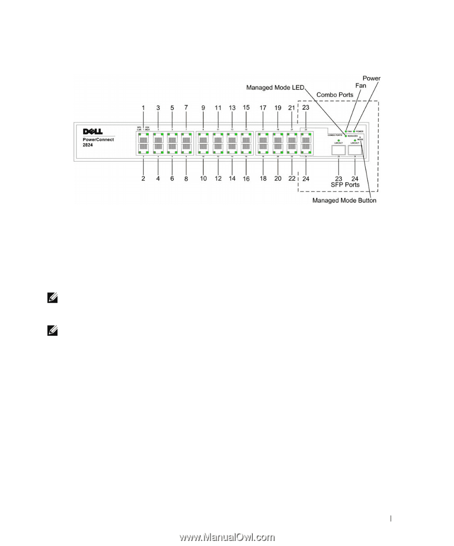
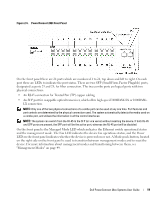
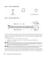
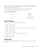
Figure 2-5. PowerConnect 2824 Front Panel On the front panel there are 24 ports which are numbered 1 to 24, top down and left to right. On each port there are LEDs to indicate the port status. There are two SFP (Small Form-Factor Plugable) ports, designated as ports 23 and 24, for fiber connection. The two combo ports are logical ports with two physical connections: • An RJ-45 connection for Twisted Pair (TP) copper cabling • An SFP port for swappable optical transceiver, which offers high-speed 1000BASE-SX or 1000BASELX connection. NOTE: Only one of the two physical connections of a combo port can be used at any one time. Port features and port controls are determined by the physical connection used. The system automatically detects the media used on a combo port, and utilizes the information in all the control interfaces. NOTE: The system can switch from the RJ-45 to the SFP (or vice versa) without resetting the device. If both RJ-45 and SFP ports are present, the SFP port will be the active port, whereas the RJ-45 port will be disabled. On the front panel is the Managed Mode LED which indicates the Ethernet switch operational status and the management mode. The Fan LED indicates the device fan operations status, and the Power LED on the front panel indicates whether the device is powered on or not. A Mode push-button, located on the right side on the front panel is used to transition between management modes and to reset the device. For more information about management modes and transitioning between them, see "Management Modes" on page 49. Dell PowerConnect 28xx Systems User Guide 19
-
 1
1 -
2
-
3
-
4
-
5
-
6
-
7
-
8
-
9
-
10
-
11
-
12
-
13
-
 14
14 -
 15
15 -
 16
16 -
 17
17 -
 18
18 -
 19
19 -
 20
20 -
 21
21 -
 22
22 -
 23
23 -
 24
24 -
25
-
26
-
27
-
28
-
29
-
30
-
31
-
32
-
33
-
34
-
35
-
36
-
37
-
38
-
39
-
40
-
41
-
42
-
43
-
44
-
45
-
46
-
47
-
48
-
49
-
50
-
51
-
52
-
53
-
54
-
55
-
56
-
57
-
58
-
59
-
60
-
61
-
62
-
63
-
64
-
65
-
66
-
67
-
68
-
69
-
70
-
71
-
72
-
73
-
74
-
75
-
76
-
77
-
78
-
79
-
80
-
81
-
82
-
83
-
84
-
85
-
86
-
87
-
88
-
89
-
90
-
91
-
92
-
93
-
94
-
95
-
96
-
97
-
98
-
99
-
100
-
101
-
102
-
103
-
104
-
105
-
106
-
107
-
108
-
109
-
110
-
111
-
112
-
113
-
114
-
115
-
116
-
117
-
118
-
119
-
120
-
121
-
122
-
123
-
124
-
125
-
126
-
127
-
128
-
129
-
130
-
131
-
132
-
133
-
134
-
135
-
136
-
137
-
138
-
139
-
140
-
141
-
142
-
143
-
144
-
145
-
146
-
147
-
148
-
149
-
150
-
151
-
152
-
153
-
154
-
155
-
156
-
157
-
158
-
159
-
160
-
161
-
162
-
163
-
164
-
165
-
166
-
167
-
168
-
169
-
170
-
171
-
172
-
173
-
174
-
175
-
176
-
177
-
178
-
179
-
180
-
181
-
182
-
183
-
184
-
185
-
186
 |
 |