Dell PowerConnect 2848 User's Guide - Page 21
Physical Dimensions, LED Definitions
 |
View all Dell PowerConnect 2848 manuals
Add to My Manuals
Save this manual to your list of manuals |
Page 21 highlights
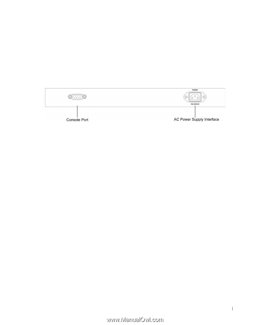
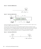
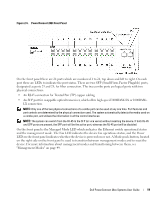
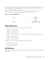
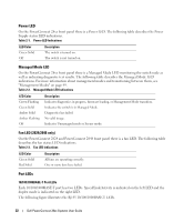
button, located on the right side on the front panel is used to transition between management modes and to reset the device. For more information about management modes and transitioning between them, see "Management Modes" on page 49. Fans are provided on the side panel. The back panel contains an AC Power Supply Interface. The following figure illustrates the back panel of the PowerConnect 2848 device. Figure 2-8. PowerConnect 2848 Back Panel Physical Dimensions The PowerConnect 2808 switch has the following physical dimensions: • Height - 43.2 mm (1.7008 in.) • Width - 256 mm (10.079 in.) • Depth - 161.7 mm (6.366 in.) The PowerConnect 2816 and PowerConnect 2824 switches have the following physical dimensions: • Height - 43.2 mm (1.7008 in.) • Width - 330 mm (12.992 in.) • Depth - 230.50 mm (9.075 in.) The PowerConnect 2848 switch has the following physical dimensions: • Height - 43.2 mm (1.70 in.) • Width - 440 mm (17.32 in) • Depth - 255 mm (10.04 in.) LED Definitions The front panel contains LEDs that indicate the status of links, power supply, fan status, and Managed Mode status. Dell PowerConnect 28xx Systems User Guide 21
-
 1
1 -
2
-
3
-
4
-
5
-
6
-
7
-
8
-
9
-
10
-
11
-
12
-
13
-
14
-
15
-
 16
16 -
 17
17 -
 18
18 -
 19
19 -
 20
20 -
 21
21 -
 22
22 -
 23
23 -
 24
24 -
 25
25 -
 26
26 -
27
-
28
-
29
-
30
-
31
-
32
-
33
-
34
-
35
-
36
-
37
-
38
-
39
-
40
-
41
-
42
-
43
-
44
-
45
-
46
-
47
-
48
-
49
-
50
-
51
-
52
-
53
-
54
-
55
-
56
-
57
-
58
-
59
-
60
-
61
-
62
-
63
-
64
-
65
-
66
-
67
-
68
-
69
-
70
-
71
-
72
-
73
-
74
-
75
-
76
-
77
-
78
-
79
-
80
-
81
-
82
-
83
-
84
-
85
-
86
-
87
-
88
-
89
-
90
-
91
-
92
-
93
-
94
-
95
-
96
-
97
-
98
-
99
-
100
-
101
-
102
-
103
-
104
-
105
-
106
-
107
-
108
-
109
-
110
-
111
-
112
-
113
-
114
-
115
-
116
-
117
-
118
-
119
-
120
-
121
-
122
-
123
-
124
-
125
-
126
-
127
-
128
-
129
-
130
-
131
-
132
-
133
-
134
-
135
-
136
-
137
-
138
-
139
-
140
-
141
-
142
-
143
-
144
-
145
-
146
-
147
-
148
-
149
-
150
-
151
-
152
-
153
-
154
-
155
-
156
-
157
-
158
-
159
-
160
-
161
-
162
-
163
-
164
-
165
-
166
-
167
-
168
-
169
-
170
-
171
-
172
-
173
-
174
-
175
-
176
-
177
-
178
-
179
-
180
-
181
-
182
-
183
-
184
-
185
-
186
 |
 |