Dell PowerConnect 2848 User's Guide - Page 22
Power LED, Managed Mode LED, Fan LED (2824/2848 only), Port LEDs, Table 2-1., Power LED Indications - firmware
 |
View all Dell PowerConnect 2848 manuals
Add to My Manuals
Save this manual to your list of manuals |
Page 22 highlights
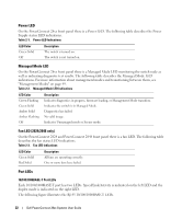
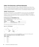
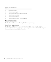
Power LED On the PowerConnect 28xx front panel there is a Power LED. The following table describes the Power Supply status LED indications. Table 2-1. Power LED Indications LED Color Green Solid Off Description The switch is turned on. The switch is not turned on. Managed Mode LED On the PowerConnect 28xx front panel there is a Managed Mode LED monitoring the switch node as well as indicating diagnostic test results. The following table describes the Managed Mode LED indications. For more information about management modes and transitioning between them, see "Management Modes" on page 49. Table 2-2. Managed Mode LED Indications LED Color Green Flashing Green Solid Amber Solid Amber Flashing Off Description Indicates diagnostics in progress, firmware loading, or Management Mode transition. Indicates the switch is in Managed Mode. Diagnostics has failed. No valid image. Indicates Unmanaged mode or Secure mode. Fan LED (2824/2848 only) On the PowerConnect 2824 and PowerConnect 2848 front panel there is a fan LED. The following table describes the fan status LED indications. Table 2-3. Fan LED Indications LED Color Green Solid Red Solid Description All fans are operating correctly. One or more fans have failed. Port LEDs 10/100/1000BASE-T Port LEDs Each 10/100/1000BASE-T port has two LEDs. Speed/Link/Activity is indicated on the left LED and the duplex mode is indicated on the right LED. The following figure illustrates the RJ-45 10/100/1000BASE-T LEDs. 22 Dell PowerConnect 28xx Systems User Guide
-
 1
1 -
2
-
3
-
4
-
5
-
6
-
7
-
8
-
9
-
10
-
11
-
12
-
13
-
14
-
15
-
16
-
 17
17 -
 18
18 -
 19
19 -
 20
20 -
 21
21 -
 22
22 -
 23
23 -
 24
24 -
 25
25 -
 26
26 -
 27
27 -
28
-
29
-
30
-
31
-
32
-
33
-
34
-
35
-
36
-
37
-
38
-
39
-
40
-
41
-
42
-
43
-
44
-
45
-
46
-
47
-
48
-
49
-
50
-
51
-
52
-
53
-
54
-
55
-
56
-
57
-
58
-
59
-
60
-
61
-
62
-
63
-
64
-
65
-
66
-
67
-
68
-
69
-
70
-
71
-
72
-
73
-
74
-
75
-
76
-
77
-
78
-
79
-
80
-
81
-
82
-
83
-
84
-
85
-
86
-
87
-
88
-
89
-
90
-
91
-
92
-
93
-
94
-
95
-
96
-
97
-
98
-
99
-
100
-
101
-
102
-
103
-
104
-
105
-
106
-
107
-
108
-
109
-
110
-
111
-
112
-
113
-
114
-
115
-
116
-
117
-
118
-
119
-
120
-
121
-
122
-
123
-
124
-
125
-
126
-
127
-
128
-
129
-
130
-
131
-
132
-
133
-
134
-
135
-
136
-
137
-
138
-
139
-
140
-
141
-
142
-
143
-
144
-
145
-
146
-
147
-
148
-
149
-
150
-
151
-
152
-
153
-
154
-
155
-
156
-
157
-
158
-
159
-
160
-
161
-
162
-
163
-
164
-
165
-
166
-
167
-
168
-
169
-
170
-
171
-
172
-
173
-
174
-
175
-
176
-
177
-
178
-
179
-
180
-
181
-
182
-
183
-
184
-
185
-
186
 |
 |