Dell PowerConnect 2848 User's Guide - Page 23
Managed Mode Button, Switch Ventilation Fan, SFP Port LED
 |
View all Dell PowerConnect 2848 manuals
Add to My Manuals
Save this manual to your list of manuals |
Page 23 highlights
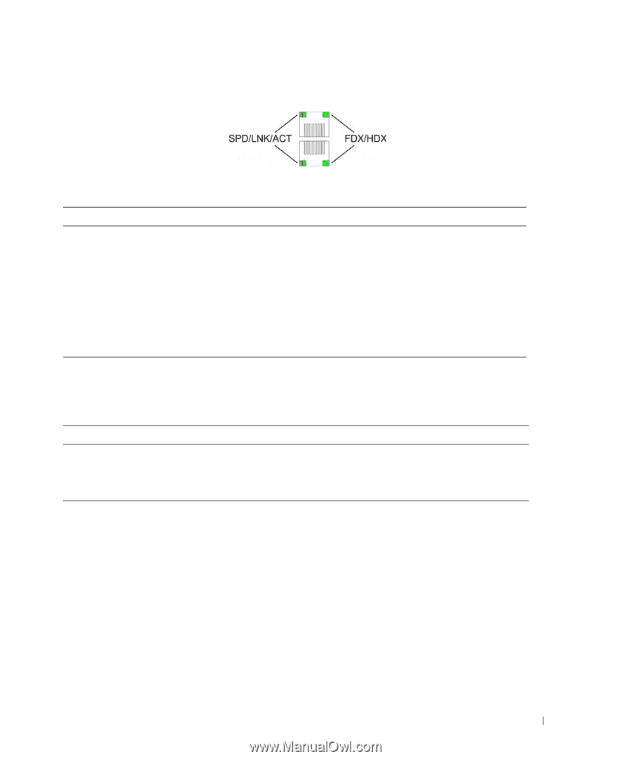
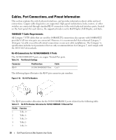
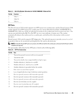
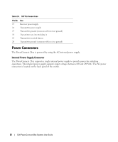
Figure 2-9. RJ-45 Copper-based 10/100/1000BASE-T LEDs The RJ-45 LED indications are described in the following table: Table 2-4. RJ-45 Copper based 10/100/ 1000BASE-T LED Indications LED Color Left LED Green Solid Green Flashing Amber Solid Amber Flashing Off Right LED Green Solid Off Description The port is linked at 1000 Mbps. The port is transmitting or receiving data at 1000 Mbps. The port is linked at either 10 or 100 Mbps. The port is transmitting or receiving data at 10 or 100 Mbps. No link is established. The port is currently transmitting in Full Duplex mode. The port is operating in Half Duplex mode. SFP Port LED The following table describes the SFP LED indications. Table 2-5. SFP LED Indications LED Color Description Green Solid Link is established. Green Flashing Activity is occurring. Off No link is established. Managed Mode Button The PowerConnect 28xx has a Mode push button on the front panel. The Mode button is for changing between Managed Mode and Unmanaged (or Secure) Mode and for resetting the device. To transition between modes, press the button normally. To reset the device, press and hold the button for at least 7 seconds. For more information about management modes and transitioning between them, see "Management Modes" on page 49. Switch Ventilation Fan The PowerConnect 2848 switch has three fans and the PowerConnect 2824 switch has one fan for system ventilation. The PowerConnect 2808 and PowerConnect 2816 devices have no internal fans. Dell PowerConnect 28xx Systems User Guide 23
-
 1
1 -
2
-
3
-
4
-
5
-
6
-
7
-
8
-
9
-
10
-
11
-
12
-
13
-
14
-
15
-
16
-
17
-
 18
18 -
 19
19 -
 20
20 -
 21
21 -
 22
22 -
 23
23 -
 24
24 -
 25
25 -
 26
26 -
 27
27 -
 28
28 -
29
-
30
-
31
-
32
-
33
-
34
-
35
-
36
-
37
-
38
-
39
-
40
-
41
-
42
-
43
-
44
-
45
-
46
-
47
-
48
-
49
-
50
-
51
-
52
-
53
-
54
-
55
-
56
-
57
-
58
-
59
-
60
-
61
-
62
-
63
-
64
-
65
-
66
-
67
-
68
-
69
-
70
-
71
-
72
-
73
-
74
-
75
-
76
-
77
-
78
-
79
-
80
-
81
-
82
-
83
-
84
-
85
-
86
-
87
-
88
-
89
-
90
-
91
-
92
-
93
-
94
-
95
-
96
-
97
-
98
-
99
-
100
-
101
-
102
-
103
-
104
-
105
-
106
-
107
-
108
-
109
-
110
-
111
-
112
-
113
-
114
-
115
-
116
-
117
-
118
-
119
-
120
-
121
-
122
-
123
-
124
-
125
-
126
-
127
-
128
-
129
-
130
-
131
-
132
-
133
-
134
-
135
-
136
-
137
-
138
-
139
-
140
-
141
-
142
-
143
-
144
-
145
-
146
-
147
-
148
-
149
-
150
-
151
-
152
-
153
-
154
-
155
-
156
-
157
-
158
-
159
-
160
-
161
-
162
-
163
-
164
-
165
-
166
-
167
-
168
-
169
-
170
-
171
-
172
-
173
-
174
-
175
-
176
-
177
-
178
-
179
-
180
-
181
-
182
-
183
-
184
-
185
-
186
 |
 |