Dell PowerConnect 2848 User's Guide - Page 25
SFP Ports, Table 2-8., SFP Pin Connections, Pin No - serial
 |
View all Dell PowerConnect 2848 manuals
Add to My Manuals
Save this manual to your list of manuals |
Page 25 highlights
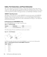
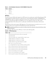
Table 2-7. RJ-45 Pin Number Allocation for 10/100/ 1000BASE-T Ethernet Port Pin No 6 7 8 Function TxRx 3TxRx 4+ TxRx 4- SFP Ports The PowerConnect 2824 switch supports two SFP transceivers combo ports, and the PowerConnect 2848 switch supports four SFP transceivers combo ports for various fiber-based modules (1000BASE-SX or 1000BASE-LX). Only one of the two physical connections of a combo port can be used at any time. The system can switch from the RJ-45 to the SFP (or vice versa) without a system reset. The system automatically detects the media used on a combo port, and utilizes this information in the control interfaces. PowerConnect 2824 switch supports SFP diagnostics. The optical transceiver provides access to a set of parameters that can be monitored and displayed to the system administrator. NOTE: If both RJ-45 and SFP ports are present, the SFP port will be the active port, whereas the RJ-45 port will be disabled and ignored. The pin number allocation for the SFP ports is listed in the following table. Table 2-8. SFP Pin Connections Pin No 1 2 3 4 5 6 7 8 9 10 11 12 13 14 Use Transmitter ground (common with receiver ground) Transmitter fault Transmitter disable; laser output disabled on high or open. Module definition 2; data line for serial ID. Module definition 1; clock line for serial ID. Module definition 0; grounded within the module. Rate select; no connection required. Loss of signal indication; logic 0 indicates normal operation. Receiver ground (common with transmitter ground) Receiver ground (common with transmitter ground) Receiver ground (common with transmitter ground) Receiver inverted data out; AC coupled. Receiver non-inverted data out; AC coupled. Receiver ground (common with transmitter ground) Dell PowerConnect 28xx Systems User Guide 25
-
 1
1 -
2
-
3
-
4
-
5
-
6
-
7
-
8
-
9
-
10
-
11
-
12
-
13
-
14
-
15
-
16
-
17
-
18
-
19
-
 20
20 -
 21
21 -
 22
22 -
 23
23 -
 24
24 -
 25
25 -
 26
26 -
 27
27 -
 28
28 -
 29
29 -
 30
30 -
31
-
32
-
33
-
34
-
35
-
36
-
37
-
38
-
39
-
40
-
41
-
42
-
43
-
44
-
45
-
46
-
47
-
48
-
49
-
50
-
51
-
52
-
53
-
54
-
55
-
56
-
57
-
58
-
59
-
60
-
61
-
62
-
63
-
64
-
65
-
66
-
67
-
68
-
69
-
70
-
71
-
72
-
73
-
74
-
75
-
76
-
77
-
78
-
79
-
80
-
81
-
82
-
83
-
84
-
85
-
86
-
87
-
88
-
89
-
90
-
91
-
92
-
93
-
94
-
95
-
96
-
97
-
98
-
99
-
100
-
101
-
102
-
103
-
104
-
105
-
106
-
107
-
108
-
109
-
110
-
111
-
112
-
113
-
114
-
115
-
116
-
117
-
118
-
119
-
120
-
121
-
122
-
123
-
124
-
125
-
126
-
127
-
128
-
129
-
130
-
131
-
132
-
133
-
134
-
135
-
136
-
137
-
138
-
139
-
140
-
141
-
142
-
143
-
144
-
145
-
146
-
147
-
148
-
149
-
150
-
151
-
152
-
153
-
154
-
155
-
156
-
157
-
158
-
159
-
160
-
161
-
162
-
163
-
164
-
165
-
166
-
167
-
168
-
169
-
170
-
171
-
172
-
173
-
174
-
175
-
176
-
177
-
178
-
179
-
180
-
181
-
182
-
183
-
184
-
185
-
186
 |
 |