Dell PowerConnect 5424 User's Guide
Dell PowerConnect 5424 Manual
 |
View all Dell PowerConnect 5424 manuals
Add to My Manuals
Save this manual to your list of manuals |
Dell PowerConnect 5424 manual content summary:
- Dell PowerConnect 5424 | User's Guide - Page 1
Dell™ PowerConnect™ 54xx Systems User Guide www.dell.com | support.dell.com - Dell PowerConnect 5424 | User's Guide - Page 2
damage to hardware or loss of data if instructions are not followed. WARNING: A WARNING indicates a potential for property damage, personal injury, or death. Information in this document is subject to change without notice. © 2007-2008 Dell Inc. All rights reserved. Reproduction of these - Dell PowerConnect 5424 | User's Guide - Page 3
Features 18 Link Aggregation 18 Layer 3 Features 19 Quality of Service Features 19 Device Management Features 20 Security Features 21 Locked Port Support 22 Additional CLI Documentation 23 2 Hardware Description 25 Device Port Configurations 25 PowerConnect 54xx Series Systems Front Panel - Dell PowerConnect 5424 | User's Guide - Page 4
Port Default Settings 38 4 Starting and Configuring the Device 39 Configure the Terminal 40 Booting the Device 40 Initial Configuration 43 Advanced Configuration 47 Retrieving an IP Address From a DHCP Server 47 Receiving an IP Address From a BOOTP Server 49 Security Management and Password - Dell PowerConnect 5424 | User's Guide - Page 5
Buttons 61 Starting the Application 62 Accessing the Device Through the CLI 62 Console Connection 62 Telnet Connection 62 Using the CLI 63 Command Mode Overview 63 User EXEC Mode 63 Privileged EXEC Mode 64 Global Configuration Mode 64 Interface Configuration Mode 65 CLI Examples - Dell PowerConnect 5424 | User's Guide - Page 6
Displaying the Log File Table 99 Viewing the Device Login History 101 Configuring the Remote Log Server Settings Page 102 Defining Device IP Addresses 107 Configuring the Internet Protocol Version 6 (IPv6 107 Defining IPv4 Default Gateways 108 Defining IPv4 Interfaces 109 Defining DHCP IPv4 - Dell PowerConnect 5424 | User's Guide - Page 7
Databases 165 Defining Line Passwords 168 Defining Enable Passwords 170 Defining TACACS+ Settings 171 Configuring RADIUS Global Parameters 176 Configuring LLDP and LLDP-MED 181 Defining LLDP Properties 182 Configuring LLDP Using CLI Commands 183 Defining LLDP Port Settings 183 Defining LLDP - Dell PowerConnect 5424 | User's Guide - Page 8
Defining iSCSI Sessions Using CLI Commands 239 7 Configuring Device Information 241 Configuring Network Security 241 Configuring Advanced Port Based Authentication 248 Authenticating Users 251 Configuring Port Security 252 ACL Overview 256 Defining MAC Based Access Control Lists 263 Defining - Dell PowerConnect 5424 | User's Guide - Page 9
Groups 337 Adding Protocol Ports 339 Configuring GVRP 340 Configuring Voice VLANs 343 Defining Voice VLAN Port Settings 347 Defining OUIs 349 Aggregating Ports 351 Defining LAG Membership 354 Multicast Forwarding Support 355 Adding Bridge Multicast Address Members 358 Assigning Multicast - Dell PowerConnect 5424 | User's Guide - Page 10
Commands 410 9 Configuring Quality of Service 411 Defining CoS Global Parameters 413 Defining QoS Interface Settings 414 Defining Bandwidth Settings 416 Defining Queue Settings 419 Mapping CoS Values to Queues 422 Mapping DSCP Values to Queues 423 10 Device Specifications 427 Port and Cable - Dell PowerConnect 5424 | User's Guide - Page 11
Device Memory Specifications 428 Feature Specifications 429 VLAN 429 Quality of Service 429 Layer 2 Multicast 429 Device Security 429 Additional Switching Features 430 Device Management 430 System Features 430 Glossary 431 Index 441 Contents 11 - Dell PowerConnect 5424 | User's Guide - Page 12
12 Contents - Dell PowerConnect 5424 | User's Guide - Page 13
downloaded from support.dell.com. This User Guide contains the information needed for installing, configuring and maintaining the PowerConnect device. PowerConnect 54xx Series Systems The PowerConnect 54xx series systems have two versions: 5424 has 24 Gigabit Ethernet ports, and 5448 has 48 Gigabit - Dell PowerConnect 5424 | User's Guide - Page 14
on enabling Jumbo Frames, see "Defining General Device Information" on page 67. MDI/MDIX Support The device supports auto-detection between crossed and straight-through cables. Standard wiring for end stations is Media-Dependent Interface (MDI) and the standard wiring for hubs and switches is - Dell PowerConnect 5424 | User's Guide - Page 15
see "Configuring Voice VLANs" on page 343. Guest VLAN Guest VLAN provides limited network access to unauthorized ports. If a port is denied network access via port-based authorization, but the Guest VLAN is enabled, the port receives limited network access. MAC Address Supported Features MAC Address - Dell PowerConnect 5424 | User's Guide - Page 16
many-to-many connections for information distribution. Layer 2 Multicast service is where a single frame is addressed to a specific Multicast address, from where copies of the frame are transmitted to the relevant ports. IGMP Snooping is supported, including IGMP Querier which simulates the behavior - Dell PowerConnect 5424 | User's Guide - Page 17
the double-tags. This allows administrators to expand service to VLAN users. GVRP Support GARP VLAN Registration Protocol (GVRP) provides IEEE 802.1Q-compliant VLAN pruning and dynamic VLAN creation on 802.1Q trunk ports. When GVRP is enabled, the device registers and propagates VLAN membership on - Dell PowerConnect 5424 | User's Guide - Page 18
) 802.1d Spanning tree is a standard Layer 2 switch requirement that allows bridges to automatically prevent and resolve L2 forwarding loops. Switches exchange configuration messages using specifically formatted frames and selectively enable and disable forwarding on ports. For more information, see - Dell PowerConnect 5424 | User's Guide - Page 19
by an IP address and a 16-bit port number. Octets streams are divided into TCP packets, each carrying a sequence number. BootP and DHCP Clients Dynamic Host Configuration Protocol (DHCP) enables additional setup parameters to be received from a network server upon system startup. DHCP service is an - Dell PowerConnect 5424 | User's Guide - Page 20
internally converts web-based input into configuration commands, MIB variable settings and other management-related settings. Configuration File Download and Upload PowerConnect device configuration is stored in a configuration file. The Configuration file includes both system wide and port specific - Dell PowerConnect 5424 | User's Guide - Page 21
, see "Configuring SNTP Settings" on page 81. Traceroute Traceroute enables discovering IP routes that packets were forwarded along during the forwarding process. The CLI Traceroute utility can be executed from either the user-exec or privileged modes. 802.1ab (LLDP-MED) The Link Layer Discovery - Dell PowerConnect 5424 | User's Guide - Page 22
information, see "Configuring Port Based Authentication" on page 243. Locked Port Support Locked Port increases network security by limiting access on a specific port only to users with specific MAC addresses. These addresses are either manually defined or learned on that port. When a frame is seen - Dell PowerConnect 5424 | User's Guide - Page 23
" on page 269. Additional CLI Documentation The CLI Reference Guide, which is available on the Documentation CD, provides information about the CLI commands used to configure the device. The document provides information including the CLI description, syntax, default values, guidelines, and examples - Dell PowerConnect 5424 | User's Guide - Page 24
24 Introduction - Dell PowerConnect 5424 | User's Guide - Page 25
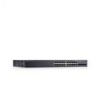
-232 console based port The following figure illustrates the PowerConnect 54xx series systems front panel. Figure 2-1. PowerConnect 5424 Front Panel The front panel contains ports1-24/48, which are copper based RJ-45 ports, designated as 10/100/1000 Mbps and support both Half and Full Duplex modes - Dell PowerConnect 5424 | User's Guide - Page 26
debugging, software download, etc. The default baud rate is 9600 bps. The baud rate can be configured from 2400 bps up to 38400 bps. Figure 2-3. Console Port Combo Ports A combo port is a single logical port with two physical connections: • A RJ-45 connection for Twisted Pair copper cabling • A SFP - Dell PowerConnect 5424 | User's Guide - Page 27
-T port of the same number is inserted and has a link. The system can switch from the RJ-45 to the SFP (or vice-versa) without a system reboot or reset. status of links, power supplies, fans, and system diagnostics. Port LEDs 10/100/1000 Base-T Port LEDs Each 10/100/1000 Base-T port has two LEDs. - Dell PowerConnect 5424 | User's Guide - Page 28
is connected, the Duplex LED on the corresponding copper Combo port is Green. System LEDs The system LEDs, located on the left side of the front panel, provide information about the power supplies, fans, thermal conditions, and diagnostics. Figure 2-6 illustrates the system LEDs. Figure 2-6. System - Dell PowerConnect 5424 | User's Guide - Page 29
The following table describes the system LED indications. Table 2-3. System LED Indications LED Diagnostics (DIAG) Fan (FAN) Redundant Power Supply (RPS) Main Power Supply (PWR) Temperature (TEMP) Color Green Flashing Green Static Red Static Green Static Red Static Green Static Red Static OFF - Dell PowerConnect 5424 | User's Guide - Page 30
the available voltage rating (110 or 220V) and no setting is required. The AC power supply unit uses a standard AC220/110V connector. LED power source, the probability of failure in the event of a power outage decreases. Reset Button The reset button, located on the front panel, manually resets - Dell PowerConnect 5424 | User's Guide - Page 31
unpacking, location, installation, and cable connections. Installation Precautions WARNING: Before performing any of the following procedures, read and follow the safety instructions located in the System Information Guide included in the Dell Documentation. WARNING: Observe the following points - Dell PowerConnect 5424 | User's Guide - Page 32
is installed within 1.5 m (5 feet) of a grounded, easily accessible outlet 220/110 VAC, 50/60 Hz. • Clearance - There is adequate frontal clearance for operator access. Allow clearance for cabling, power connections and ventilation. • Cabling - Cabling is routed to avoid sources of electrical noise - Dell PowerConnect 5424 | User's Guide - Page 33
Redundant Power Supply (UPS) is optional, but is recommended. The UPS DC connector is located on the back panel of the device. Mounting the System Device Rack Installation WARNING: Disconnect all cables from mounting bracket on the other side of the device. Installing the PowerConnect Device 33 - Dell PowerConnect 5424 | User's Guide - Page 34
be able to support the weight of the device and the device cables. 1 Install rubber feet provided with the device. 2 Set the device on Console port, that enables a connection to a terminal desktop system running terminal emulation software for monitoring and configuring the device. The Console port - Dell PowerConnect 5424 | User's Guide - Page 35
2000 service packs. 3 Connect the female connector of the RS-232 crossover cable directly to the device Console port, and tighten the captive retaining screws. The device Console port is located on the back panel. Figure 3-2. Connecting to PowerConnect 54xx Series Systems Console Port RS-232 - Dell PowerConnect 5424 | User's Guide - Page 36
the twisted-pair ports, Tx pair on one cable end must be connected to the Rx pair on the other cable end, and vice versa. If the cabling is done such that Tx on one end is wired to Tx on the other end, and Rx is wired to Rx, a link is not established. 36 Installing the PowerConnect Device - Dell PowerConnect 5424 | User's Guide - Page 37
TxRx 4- Port Default Settings The general information for configuring the device ports includes the short description of the auto-negotiation mechanism and the default settings for switching ports. Auto-Negotiation Auto-negotiation enables automatic detection of speed, duplex mode and flow control - Dell PowerConnect 5424 | User's Guide - Page 38
for end stations is known as MDI (Media Dependent Interface), and the standard wiring for hubs and switches is known as MDIX.) Flow Control The device supports 802.3x Flow Control for ports configured with the Full Duplex mode. By default, this feature is disabled. It can be enabled per port. The - Dell PowerConnect 5424 | User's Guide - Page 39
.support.dell.com. Figure 4-1. Installation and Configuration Flow Connect Device and Console Hardware Setup Power On Press Esc Yes Susepnd Bootup No Loading Program from flash to RAM Startup Menu (Special Functions) Enter Wizard Yes Reboot No Initial Configuration: IP Address, Subnet - Dell PowerConnect 5424 | User's Guide - Page 40
2000 service packs. Booting the Device NOTE: The assumed bootup information is as follows: • The device is delivered with a default configuration. • The device is not configured with a default user name and password. To boot the device, perform the following: 1 Ensure that the device Serial port is - Dell PowerConnect 5424 | User's Guide - Page 41
------ Performing the Power-On Self Test KB. D-Cache 8 KB. Cache Enabled. Autoboot in 2 seconds - press RETURN end of POST (see the last lines) indicates that no problems ports and their states (up or down) are displayed. NOTE: The following screen is an example configuration. Items such as addresses - Dell PowerConnect 5424 | User's Guide - Page 42
1 - PowerConnect 5448 Unit Standalone Run eeprom code for asic 0 Run eeprom code for asic 1 Tapi Version: v1.3.3.1 Core Version: v1.3.3.1 01-Jan-xxxx 01:01:59 %INIT-I-InitCompleted: Initialization task is completed 01-Jan-xxxx 01:02:00 %SNMP-I-CDBITEMSNUM: Number of running configuration items - Dell PowerConnect 5424 | User's Guide - Page 43
and SNMP management system IP address (optional) • Username and password The Setup Wizard guides you through the initial switch configuration, and gets the system up and running as quickly as possible. You can skip the Setup Wizard, and manually configure the device through the device CLI mode - Dell PowerConnect 5424 | User's Guide - Page 44
The Setup Wizard configures the following fields. • SNMP Community String and SNMP Management System IP address (optional) • Username and Password • Device IP address • Default Gateway IP address The following is displayed: Welcome to Dell Easy Setup Wizard The Setup Wizard guides you through the - Dell PowerConnect 5424 | User's Guide - Page 45
management system IP address and the "community string" or password that the particular management system uses to access the switch. The wizard automatically assigns the highest access level [Privilege Level 15] to this account. You can use Dell Network Manager or CLI to change this setting, and to - Dell PowerConnect 5424 | User's Guide - Page 46
is displayed: Next, an IP address is setup. The IP address is defined on the default VLAN (VLAN #1), of which all ports are members. This is the IP address you use to access the CLI, Web interface, or SNMP interface for the switch.To setup an IP address: Please enter the IP address of the device - Dell PowerConnect 5424 | User's Guide - Page 47
the selected port for receiving the IP address. In the following example, the commands are based on the port type used for configuration. • Assigning Dynamic IP Addresses: console# configure console(config)# interface ethernet g1 console(config-if)# ip address dhcp hostname device console(config-if - Dell PowerConnect 5424 | User's Guide - Page 48
• Assigning Dynamic IP Addresses (on a VLAN): console# configure console(config)# interface ethernet vlan 1 console(config-if)# ip address dhcp hostname device console(config-if)# exit console(config)# 3 To verify the IP address, enter the show ip interface command at the system prompt as shown in - Dell PowerConnect 5424 | User's Guide - Page 49
This command will reset the whole system and disconnect your current session. Do you want to continue (y/n) [n]? /* the switch reboots */ To verify the IP address, enter the show ip interface command. The device is now configured with an IP address. Security Management and Password Configuration - Dell PowerConnect 5424 | User's Guide - Page 50
access the Web interface with any password. Configuring an Initial Terminal Password To configure an initial terminal password, enter the following commands: console(config)# aaa authentication login default line console(config)# aaa authentication enable default line console(config)# line console - Dell PowerConnect 5424 | User's Guide - Page 51
the password prompt. • When changing a device's mode to enable, enter jones. Configuring an Initial HTTP Password To configure an initial HTTP password, enter the following commands: console(config)# ip http authentication local console(config)# username admin password user1 level 15 Configuring an - Dell PowerConnect 5424 | User's Guide - Page 52
When initially enabling an http or https session, enter admin for user name and user1 for password. NOTE: Http and Https services require level 15 access and connect directly to the configuration level access. Configuring Login Banners You can define 3 types of login banners: • Message-of-the-Day - Dell PowerConnect 5424 | User's Guide - Page 53
KB. D-Cache 8 KB. Cache Enabled. Autoboot in 2 seconds - HyperTerminal. [1] Download Software [2] Erase Flash File [3] Password Recovery Procedure [4] Enter Diagnostic Mode [5] Set default), the device times out. This default value can be changed through CLI. Starting and Configuring the Device 53 - Dell PowerConnect 5424 | User's Guide - Page 54
config as the name of the flash file. The configuration is erased and the device reboots. 4 Repeat the device initial configuration. Password Recovery If a password is lost, the Password Recovery procedure can be called from the Startup menu. The procedure enables entry to the device once without - Dell PowerConnect 5424 | User's Guide - Page 55
next boot, the device will decompress and run the currently active system image unless chosen otherwise. To download a system image through the TFTP server: 1 Ensure that an IP address is configured on one of the device ports and pings can be sent to a TFTP server. 2 Make sure that the file to be - Dell PowerConnect 5424 | User's Guide - Page 56
from the currently active image. 7 Enter the reload command. The following message is displayed: console# reload This command will reset the whole system and disconnect your current session. Do you want to continue (y/n) [n]? 8 Enter y. The device reboots. 56 Starting and Configuring the Device - Dell PowerConnect 5424 | User's Guide - Page 57
programming it into the flash updates the boot image. The boot image is loaded when the device is powered on. A user has no control over the boot image copies. To download a boot image through the TFTP server: 1 Ensure that an IP address is configured on one of the device ports and pings can be sent - Dell PowerConnect 5424 | User's Guide - Page 58
58 Starting and Configuring the Device - Dell PowerConnect 5424 | User's Guide - Page 59
Using Dell OpenManage Switch Administrator This section provides an introduction to the user interface. provides a view of the device, an information or table area, and configuration instructions. Figure 5-1. Switch Administrator Components Using Dell OpenManage Switch Administrator 59 - Dell PowerConnect 5424 | User's Guide - Page 60
information about device ports, current configuration and status, table access to Dell Support. For more information, see "Information Buttons." Device Representation The PowerConnect home page contains a graphical device representation of the front panel. Figure 5-2. Port LED Indicators The port - Dell PowerConnect 5424 | User's Guide - Page 61
Buttons Button Support Help About Log Out Description Opens the Dell Support page at support.dell.com. Online help containing information to assist in configuring and managing the device. The online help pages are linked directly to the page currently open. For example, if the IP Addressing - Dell PowerConnect 5424 | User's Guide - Page 62
a lost password, see "Password Recovery." NOTE: Passwords are both case sensitive and alpha-numeric. 4 Click OK. The Dell PowerConnect OpenManage™ Switch Administrator home page opens. Accessing the Device Through the CLI The device can be managed over a direct connection to the console port or via - Dell PowerConnect 5424 | User's Guide - Page 63
EXEC mode. Only a limited subset of commands are available in the User EXEC mode. This level is reserved for tasks that do not change the console configuration and is used to access configuration sub-systems such as the CLI. To enter the next level, the Privileged EXEC mode, a password is required - Dell PowerConnect 5424 | User's Guide - Page 64
/end, or . The following example illustrates accessing privileged EXEC mode and then returning to the User EXEC mode: console>enable Enter Password: ****** console# console#disable console> Use the exit command to move back to a previous mode. For example, from Interface Configuration mode - Dell PowerConnect 5424 | User's Guide - Page 65
illustrates how to access Global Configuration Mode and return back to the Privileged EXEC Mode: console# console#configure console(config)#exit console# Interface Configuration Mode Interface configuration commands modify specific IP interface settings, including bridge-group, description, etc - Dell PowerConnect 5424 | User's Guide - Page 66
mode: Console(config)# crypto key pubkey-chain ssh Console(config-pubkey-chain)# CLI Examples CLI commands are provided as configuration examples. For a full description of the CLI commands, including examples, refer to the "CLI Reference Guide" included on the Documentation CD. 66 Using Dell - Dell PowerConnect 5424 | User's Guide - Page 67
parameters including security features, downloading device software, and resetting the device. To open the System page, click System in the tree view. Figure 6-1. System Defining General Device Information The General page contains links to pages for configuring device parameters. Viewing Device - Dell PowerConnect 5424 | User's Guide - Page 68
Address - Specifies the device MAC address. • Sys Object ID - Specifies the vendor's authoritative identification of the network management subsystem contained in the entity. • Service Tag - Specifies the service reference number used when servicing since the last device reset. The system time is - Dell PowerConnect 5424 | User's Guide - Page 69
. Configuring Device Information Using the CLI Commands The following table summarizes the equivalent CLI commands for viewing and setting fields displayed in the Asset page. Table 6-1. Asset CLI Commands CLI Command Description hostname name Specifies or modifies the device host name. snmp - Dell PowerConnect 5424 | User's Guide - Page 70
The following is an example of the CLI commands: Console (config)# hostname dell Console (config)# snmp-server contact Dell_Tech_Supp Console (config)# snmp-server location New_York Console (config)# exit Console # exit Console (config)# asset-tag 1qwepot Console> clock set 13:32:00 7 Dec 2004 - Dell PowerConnect 5424 | User's Guide - Page 71
Defining System Time Settings The Time local hardware clock. Daylight Savings Time can be enabled on the device. The following is a list of Daylight Time start and end times in specific countries: • Albania - Last March until the last weekend of October. Configuring System Information 71 - Dell PowerConnect 5424 | User's Guide - Page 72
America - From the second Sunday in March at 02:00 to the first Sunday in November at 02:00. For more information on SNTP, see "Configuring SNTP Settings" on page 81. To open the Time Synchronization page, click System → General → Time Synchronization in the tree view. 72 - Dell PowerConnect 5424 | User's Guide - Page 73
field values are: - SNTP - Specifies that the system time is set via an SNTP server. For more information, see "Configuring SNTP Settings" on page 81. - None - Specifies that the system time is not set by an external source. Local Settings • Date - Defines the system date. The field format is Day - Dell PowerConnect 5424 | User's Guide - Page 74
. The possible field range is 1-31. - Month - The month of the year in which DST ends. The possible field range is Jan-Dec. - Year- The year in which the configured DST ends. - Time - The time at which DST starts. The field format is Hour:Minute, for example, 05:30. • Recurring - Defines the time - Dell PowerConnect 5424 | User's Guide - Page 75
at which DST ends every year. The field format is Hour:Minute, for example, 05:30. Selecting a Clock Source 1 Open the Time Synchronization page. 2 Define the Clock Source field. 3 Click Apply Changes. The Clock source is selected, and the device is updated. Defining Local Clock Settings 1 Open the - Dell PowerConnect 5424 | User's Guide - Page 76
-time date date Configures the system to automatically switch to month year hh:mm date summer time (Daylight Savings Time) for a month year hh:mm [offset specific period - date/month/year format. offset] [zone acronym] The following is an example of the CLI commands: Console(config)# clock - Dell PowerConnect 5424 | User's Guide - Page 77
Health Information Using the CLI Commands The following table summarizes the equivalent CLI command for viewing fields displayed in the System Health page. Table 6-3. System Health CLI Commands CLI Command show system Description Displays system information. Configuring System Information 77 - Dell PowerConnect 5424 | User's Guide - Page 78
): System Contact: System Name: System Location: System MAC Address: Sys Object ID: Type: PowerConnect 5400 Power Supply Main Redundant Status -------OK OK FAN 1 2 Status -------OK OK DELL Switch# Ethernet Routing Switch 0,00:04:17 spk DELL Switch R&D 00:10:b5:f4:00:01 1.3.6.1.4.1.674.10895 - Dell PowerConnect 5424 | User's Guide - Page 79
CLI Commands CLI Command show version Description Displays system version information. The following is an example of the CLI commands: Console> show version SW version x.xxx (date 23-Jul-xxxx time 17:34:19) Boot version x.xxx (date 17-Jan-xxxx time 11:48:21) HW version x.x.x Configuring - Dell PowerConnect 5424 | User's Guide - Page 80
password to reconnect to the Web Interface. Resetting the Device Using the CLI The following table summarizes the equivalent CLI commands for performing a reset of the device via the CLI: Table 6-5. Reset CLI Command CLI Command reload Description Reloads the operating system. 80 Configuring - Dell PowerConnect 5424 | User's Guide - Page 81
The following is an example of the CLI command: Console >reload This command will reset the whole system and disconnect your current session. Do you want to continue (y/n) [n] ? Configuring SNTP Settings The device supports the Simple Network Time Protocol (SNTP). SNTP assures accurate network - Dell PowerConnect 5424 | User's Guide - Page 82
is used to set the time value. Time levels T3 and T4 are used to determine the server time. Using Anycast time information for synchronizing switch time is preferred to using Broadcast time information. Broadcast Time Information Broadcast information is used when the server IP address is unknown - Dell PowerConnect 5424 | User's Guide - Page 83
sntp broadcast client enable Enables SNTP broadcast clients sntp anycast client enable Enables SNTP anycast clients sntp unicast client enable Enables SNTP predefined unicast clients The following is an example of the CLI commands: console> enable console# configure console(config)# sntp anycast - Dell PowerConnect 5424 | User's Guide - Page 84
Figure 6-8. SNTP Authentication • SNTP Authentication - Enables authenticating an SNTP session between the device and an SNTP server, when enabled. • Encryption Key ID - Defines the Key the SNTP server. • Remove - Removes SNTP Authentication when selected. 84 Configuring System Information - Dell PowerConnect 5424 | User's Guide - Page 85
. The Add Authentication Key page opens: Figure 6-9. Add Authentication Key 3 Define the fields. 4 Click Apply Changes. The SNTP Authentication Key is added, and the device is updated. Displaying the Authentication Key Table 1 Open the SNTP Authentication page. 2 Click Show All. The Authentication - Dell PowerConnect 5424 | User's Guide - Page 86
an authentication key for SNTP. The following is an example of the CLI commands: console> enable console# configure Console(config)# sntp authentication-key 8 md5 ClkKey Console(config)# sntp trusted-key 8 Console(config)# sntp authenticate Defining SNTP Servers The SNTP Servers page contains - Dell PowerConnect 5424 | User's Guide - Page 87
IP addresses or hostname. Up to eight SNTP servers can be defined. This field can contain 1 - 158 characters. • Poll Interval - Enables polling the selected SNTP Server for system time information, when enabled clock and the acquired time from the SNTP server. Configuring System Information 87 - Dell PowerConnect 5424 | User's Guide - Page 88
by the SNTP server. The possible values are: - IPv6 - IP version 6 is supported. - IPv4 - IP version 4 is supported. • IPv6 Address Type - When the server supports IPv6 (see previous parameter), this specifies the type of static address supported. The possible values are: - Link Local - A Link Local - Dell PowerConnect 5424 | User's Guide - Page 89
SNTP Server CLI Commands CLI Command sntp server {ipv4-address|ipv6address|hostname [poll] [key keyid] Description Configures the device to use SNTP to request and accept NTP traffic from a server. The following is an example of the CLI commands: console> enable console# configure Console(config - Dell PowerConnect 5424 | User's Guide - Page 90
traffic from as server. The following is an example of the CLI commands: console> enable console# configure Console(config)# sntp server 100.1.1.1 poll key 10 Console# show sntp status Clock is synchronized, stratum 4, reference is 176.1.1.8 Reference time is AFE2525E.70597B34 (00:10:22.438 PDT Jul - Dell PowerConnect 5424 | User's Guide - Page 91
19 119.89 Broadcast: Interface IP address 176.1.1.8 Primary 176.1.8.179 Secondary Settings. The SNTP Broadcast Interface Table contains the following fields: • Interface - Contains an interface list on which SNTP can be enabled. • Receive Servers Updates - Whether SNTP server updates are enabled - Dell PowerConnect 5424 | User's Guide - Page 92
updated. Defining SNTP Interface Settings Using CLI Commands The following table summarizes the equivalent CLI commands for setting fields displayed in the SNTP Broadcast Interface Table. Table 6-10. SNTP Broadcast CLI Commands CLI Command sntp client enable show sntp configuration Description - Dell PowerConnect 5424 | User's Guide - Page 93
The following is an example of the CLI commands: Console# show sntp configuration Polling interval: 7200 seconds. MD5 Authentication keys: 8, 9 Authentication is required for synchronization. Trusted Keys: 8,9 Unicast Clients Polling: Enabled. Server ----------176.1.1.8 176.1.8.179 Polling - Dell PowerConnect 5424 | User's Guide - Page 94
has occurred. Informational 6 Provides device information. Debug 7 Provides detailed information about the log. If a Debug error occurs, contact Dell Online Technical Support The Global Log Parameters page contains fields for defining which events are recorded to which logs. It contains - Dell PowerConnect 5424 | User's Guide - Page 95
log severity in the Global Log Parameters check boxes. 4 Click Apply Changes. The log settings are saved, and the device is updated. Enabling Logs Using CLI Commands The following table summarizes the equivalent CLI commands for setting fields displayed in the Global Log Parameters page. Table 6-11 - Dell PowerConnect 5424 | User's Guide - Page 96
)# logging console errors Console (config)# logging buffered debugging Console (config)# logging file alerts Console (config)# clear logging Console (config)# exit Console# clear logging file Clear Logging File [y/n]y Console# show syslog-servers Device Configuration IP address Port facility - Dell PowerConnect 5424 | User's Guide - Page 97
Clear Log. The log information is removed from the RAM Log Table, and the device is updated. Viewing and Clearing the RAM Log Table Using the CLI Commands The following table summarizes the equivalent CLI commands for viewing and clearing fields displayed in the RAM Log Table. Table 6-12. RAM Log - Dell PowerConnect 5424 | User's Guide - Page 98
The following is an example of the CLI commands: console# show logging Logging is enabled. Console Logging: Level info. Console Messages: 0 Dropped. Buffer Logging: Level info task is completed Console # clear logging clear logging buffer [y/n]? Console # 98 Configuring System Information - Dell PowerConnect 5424 | User's Guide - Page 99
viewing and setting fields displayed in the Log File Table. Table 6-13. Log File Table CLI Commands CLI Command show logging file clear logging file Description Displays the logging state and the syslog messages stored in the logging file. Clears messages from the logging file. Configuring System - Dell PowerConnect 5424 | User's Guide - Page 100
CLI commands: Console # show logging file Logging is enabled. Console Logging: Level info. Console changed from copper media to fiber media (1000BASE-SX) on port g21. 01-Jan-2000 01:11:48 :%2SWPHY-I-CHNGCOMBOMEDIA: Media changed from fiber media to copper media on port g21. 01-Jan-2000 01:11:48 - Dell PowerConnect 5424 | User's Guide - Page 101
• Location - Indicates the IP address of the station from which the device was accessed. Viewing Login History 1 Open the Login History page. 2 Select a user in the User Name field. 3 Click Apply Changes. The login information for the selected user is displayed. Configuring System Information 101 - Dell PowerConnect 5424 | User's Guide - Page 102
Displays password management history information. The following is an example of the CLI commands: console# show users login-history Login Time ----------- Jan 1. 2005 23:58:17 Jan 1. 2005 07:59:23 Jan 1. 2005 08:23:48 Jan 1. 2005 08:29:29 Jan 1. 2005 08:42:31 Jan 1. 2005 08:49:52 Username - Dell PowerConnect 5424 | User's Guide - Page 103
Settings • Available Servers - Contains a list of servers to which logs can be sent. • UDP Port (1-65535) - The UDP port to which the logs are sent for the selected server. The possible range is 1 - 65535. The default state. - Error - A system error has occurred. Configuring System Information 103 - Dell PowerConnect 5424 | User's Guide - Page 104
following additional parameters are available: • Supported IP Format - Specifies the IP format supported by the server. The possible values are: - IPv6 - IP version 6 is supported. - IPv4 - IP version 4 is supported. • IPv6 Address Type - When the server supports IPv6 (see previous parameter), this - Dell PowerConnect 5424 | User's Guide - Page 105
the fields. 4 Select the log severity in the Severity to Include check boxes. 5 Click Apply Changes. The log settings are saved, and the device is updated. Defining a New Server: 1 Open the Remote Log Server Settings page. 2 Click Add. The Add a Log Server page opens: Figure 6-20. Add a Log Server - Dell PowerConnect 5424 | User's Guide - Page 106
device is updated. Working with Remote Server Logs Using the CLI Commands The following table summarizes the equivalent CLI command for working with remote server logs. Table 6-15. Remote Log Server CLI Commands CLI Command logging (ipv4-address|ipv6-addres |hostname) [port port] [severity level - Dell PowerConnect 5424 | User's Guide - Page 107
The following is an example of the CLI commands: console> enable console# configure console (config) # logging 10.1.1.1 severity critical Console# show logging Logging is enabled. Console Logging: Level debug. Console Messages: 5 Dropped. Buffer Logging: Level debug. Buffer Messages: 16 Logged, 16 - Dell PowerConnect 5424 | User's Guide - Page 108
. Packets are forwarded to the default IP when frames are sent to a remote network. The configured IP address must belong to the same IP address subnet of one of the IP interfaces. To open the IPv4 Default Gateway page, click System→ IP Addressing → IPv4 Default Gateway in the tree view. Figure - Dell PowerConnect 5424 | User's Guide - Page 109
for setting fields displayed in the Default Gateway page. Table 6-16. IPv4 Default Gateway CLI Commands CLI Command ip default-gateway ipaddress no ip default-gateway Description Defines a default gateway. Removes a default gateway. The following is an example of the CLI commands: Console (config - Dell PowerConnect 5424 | User's Guide - Page 110
IP address. • Prefix Length - The number of bits that comprise the source IP address prefix, or the network mask of the source IP address. • Interface - The interface type for which the IP address is defined. Select Port, LAG, or VLAN. • Type - Indicates whether or not the IP address was configured - Dell PowerConnect 5424 | User's Guide - Page 111
Interface page. 2 Click Show All. The IPv4 Interface Parameters Table opens: Figure 6-25. IPv4 Interface Parameter Table 3 Select an IP address and select the Remove check box. 4 Click Apply Changes. The selected IP address is deleted, and the device is updated. Configuring System Information 111 - Dell PowerConnect 5424 | User's Guide - Page 112
prefix-length} Sets an IP address. no ip address [ip-address] Removes an IP address show ip interface [ethernet interface-number Displays the usability status of interfaces configured for IP. | vlan vlan-id | port-channel number] The following is an example of the CLI commands: Console (config - Dell PowerConnect 5424 | User's Guide - Page 113
device interfaces. Click System→ IP Addressing→ DHCP IPv4 Interface in the tree view. To open the DHCP IPv4 Interface page. Figure 6-26. DHCP IPv4 Interface • Interface - The specific interface on which the DHCP client is configured. Click the option button next to Port, LAG, or VLAN and select the - Dell PowerConnect 5424 | User's Guide - Page 114
CLI Commands CLI Command Description ip address dhcp To acquire an IP address on an Ethernet interface from the [hostname host-name] Dynamic Host Configuration Protocol (DHCP). The following is an example of the CLI command: console> enable console# config console (config#) interface ethernet - Dell PowerConnect 5424 | User's Guide - Page 115
The system supports IPv6 hosts. The IPv6 Interface page contains fields for defining IPv6 interfaces. To open the IPv6 Interface page, click System→ IP Addressing→ IPv6 Interface in the tree view. Figure 6-27. IPv6 Interface • Interface - The IPv6 interface that has been selected for configuration - Dell PowerConnect 5424 | User's Guide - Page 116
. • Send ICMP Unreachable - Specifies whether transmision of ICMPv6 Address Unreachable messages is enabled. When enabled, unreachable messages are generated for any packet arriving on the interface with unassigned TCP/UDP port. Default is Enabled. • ICMP Error Rate Limit Interval - The rate-limit - Dell PowerConnect 5424 | User's Guide - Page 117
traffic. - Active - Indicates the IPv6 address is set to active. • Remove - When selected, removes the address from the table. Adding an IPv6 Interface is a specific port, LAG or VLAN. 4 Click Apply Changes. The new interface is added, and the device is updated. Configuring System Information 117 - Dell PowerConnect 5424 | User's Guide - Page 118
new address is added, and the device is updated. Modifying IPv6 Interface Parameters 1 Open the IPv6 Interface page. 2 Select an interface in the Interface drop-down menu. 3 Modify the required fields. 4 Click Apply Changes. The parameters are modified, and the device is updated. 118 Configuring - Dell PowerConnect 5424 | User's Guide - Page 119
equivalent CLI commands for setting fields displayed in the IPv6 Interface page. Table 6-19. IPv6 Interface CLI Commands CLI Command Description ipv6 enable [no-autoconfig] Enables IPv6 processing on an interface. ipv6 address autoconfig Enables automatic configuration of IPv6 addresses using - Dell PowerConnect 5424 | User's Guide - Page 120
The following is an example of the CLI commands: console# show ipv6 interface vlan 1 Number of ND DAD attempts: 1 MTU size: 1500 Stateless Address Autoconfiguration state: enabled ICMP unreachable message state: enabled MLD version: 2 IP addresses Type fe80::232:87ff:fe08:1700 linklayer ff02 - Dell PowerConnect 5424 | User's Guide - Page 121
IP Address - Displays the Link Local IPv6 address of the default gateway. • Interface - Specifies the outgoing interface through which the default gateway can be reached. Interface refers to any Port/LAG/VLAN and/or Tunnel. • Type - Specifies the means by which the default gateway was configured - Dell PowerConnect 5424 | User's Guide - Page 122
Using CLI Commands The following table summarizes the equivalent CLI commands for setting fields displayed in the IPv6 Default Gateway page. Table 6-20. IPv6 Default Gateway CLI Commands CLI Command ipv6 default-gateway ipv6-address Description Defines an IPv6 default gateway. 122 Configuring - Dell PowerConnect 5424 | User's Guide - Page 123
on top of an IPv4 network. When enabling ISATAP on a tunnel interface, an explicit IP address is configured as the tunnel source or an automatic mode exists where the lowest IPv4 address is assigned to an IP interface. This source IPv4 is used for setting the tunnel interface identifier according to - Dell PowerConnect 5424 | User's Guide - Page 124
that represents a specific automatic tunnel router domain name. The default value is ISATAP. - Use Default - Selecting the check box returns settings to default. • Domain Name Query Interval - Specifies the interval between DNS Queries (before the IP address of the ISATAP router is known) for the - Dell PowerConnect 5424 | User's Guide - Page 125
the equivalent CLI commands for setting fields displayed in the IPv6 ISATAP Tunnel page. Table 6-21. IPv6 Default Gateway CLI Commands CLI Command interface tunnel number tunnel mode ipv6ip {isatap} tunnel isatap router router_name tunnel source { auto | ip-address ipv4address | interface - Dell PowerConnect 5424 | User's Guide - Page 126
System→ IP Addressing→ IPv6 Neighbors in the tree view. Figure 6-33. IPv6 Neighbors • Interface - Displays the interface on which IPv6 Interface is defined. Interfaces include Ports, LAGs, or VLANs. • IPv6 Address - Defines the currently configured neighbor IPv6 address. • MAC Address - Displays - Dell PowerConnect 5424 | User's Guide - Page 127
possible values are: • Incomplete - Indicates that an address resolution is in progress and the link-layer address of the neighbor has not yet been determined. • the fields on the page. 4 Click Apply Changes. The new neighbor is added, and the device is updated. Configuring System Information 127 - Dell PowerConnect 5424 | User's Guide - Page 128
Modifying Neighbor Parameters 1 Open the IPv6 Neighbors page. 2 Select an IP address in the IPv6 Address drop-down menu. 3 Modify the required fields. 4 Click Apply Changes. The parameters are modified, and the device is updated. Deleting Neighbors 1 Open the IPv6 Neighbors page. 2 Click Show All. - Dell PowerConnect 5424 | User's Guide - Page 129
cache dynamic}[ipv6-address ipv6- information. address] [mac-address macaddress] [ethernet interfacenumber | vlan vlan-id | portchannel number ] clear ipv6 neighbors Deletes all entries in the IPv6 neighbor discovery cache. The following is an example of the CLI commands: Console# show ipv6 - Dell PowerConnect 5424 | User's Guide - Page 130
field is applicable only when the IPv6 Static IP address is defined as a Global IPv6 address. The range is 5 - 128. • Interface - Displays the interface that is used to forward the packet. Interface refers to any Port, LAG or VLAN. • Next Hop - Defines the address to which the packet is forwarded on - Dell PowerConnect 5424 | User's Guide - Page 131
packet_size] [ttl max-ttl] [count packet_count] [timeout time_out] [source ip-address] [tos tos] show ipv6 route Displays the current state of the ipv6 routing table. The following is an example of the CLI commands: Console> show ipv6 route Codes: L - Local, S - Static, I - ICMP, ND - Router - Dell PowerConnect 5424 | User's Guide - Page 132
Configuring Domain Name Systems Domain Name System (DNS) converts user-defined domain names into IP addresses. Each time a domain name is assigned the DNS service translates the name into a numeric IP address • DNS Status - Enables or disables translating DNS names into IP addresses. • DNS Server - - Dell PowerConnect 5424 | User's Guide - Page 133
following additional parameters are available: • Supported IP Format - Specifies the IP format supported by the server. The possible values are: - IPv6 - IP version 6 is supported. - IPv4 - IP version 4 is supported. • IPv6 Address Type - When the server supports IPv6 (see previous parameter), this - Dell PowerConnect 5424 | User's Guide - Page 134
Changes. The selected DNS server is deleted, and the device is updated. Configuring DNS Servers Using the CLI Commands The following table summarizes the CLI commands for configuring device system information. Table 6-24. DNS Server CLI Commands CLI Command ip name-server server-address no ip - Dell PowerConnect 5424 | User's Guide - Page 135
of the CLI commands: console> enable Console# configure console (config)# ip name-server 176.16.1.18 Defining Default Domains The Default Domain Name page provides information for defining default DNS domain names. To open the Default Domain Name page, click System→ IP Addressing→ Default Domain - Dell PowerConnect 5424 | User's Guide - Page 136
an example of the CLI commands: console> enable console# configure console (config)# ip domain-name www.dell.com Mapping Domain Host The Host Name Mapping page provides parameters for assigning static host names IP addresses. The Host Name Mapping page provides up to eight IP addresses per host. To - Dell PowerConnect 5424 | User's Guide - Page 137
Host Name Mapping page. 2 Click Add. The Add Host Name Mapping page opens: Figure 6-42. Add Host Name Mapping 3 Define the relevant fields. 4 Click Apply Changes. The IP address is mapped to the Host Name, and the switch device is updated. Configuring System Information 137 - Dell PowerConnect 5424 | User's Guide - Page 138
Changes. The Host Mapping Table entry is deleted, and the switch device is updated. Mapping IP address to Domain Host Names Using the CLI Commands The following table summarizes the equivalent CLI commands for mapping Domain Host names to IP addresses. Table 6-26. Domain Host Name CLI Commands CLI - Dell PowerConnect 5424 | User's Guide - Page 139
entries from the host name-to-address cache. Displays the default domain name, list of name server hosts, the static and the cached list of host names and addresses. The following is an example of the CLI commands: console# enable console# configure console (config)# ip host accounting.abc.com 176 - Dell PowerConnect 5424 | User's Guide - Page 140
the cache. The default value is 60000 settings on a single device. • Interface - The interface number of the port, LAG, or VLAN that is connected to the device. • IP Address - The station IP address, which is associated with the MAC address filled in below. • MAC Address - The station MAC address - Dell PowerConnect 5424 | User's Guide - Page 141
46. ARP Table Page Deleting ARP Table Entry 1 Open the ARP Settings page 2 Click Show All. The ARP Table page opens. 3 Select a table entry. 4 Select the Remove check box. 5 Click Apply Changes. The selected ARP Table entry is deleted, and the device is updated. Configuring System Information 141 - Dell PowerConnect 5424 | User's Guide - Page 142
. The following is an example of the CLI commands: Console(config)# arp 198.133.219.232 00-00-0c-40-0f-bc Console (config)# exit Console# arp timeout 12000 Console# show arp ARP timeout: 80000 Seconds Interface IP address HW address ---------- Status ------ g1 10.7.1.102 00:10:B5 - Dell PowerConnect 5424 | User's Guide - Page 143
port. - Open Cable - The cable is connected on only one side. - Short Cable - A short has occurred in the cable. - OK - The cable passed the test. - Fiber Cable - A fiber cable is connected to the port. • Cable Fault Distance - The distance from the port where the cable error occurred. • Last Update - Dell PowerConnect 5424 | User's Guide - Page 144
tests on ports. show copper-port cable-length Displays the estimated copper cable length attached to a [interface] port. The following is an example of the CLI commands: console> enable Console# test copper-port tdr g3 Cable is open at 100 meters. Console> show copper-ports tdr Port Result - Dell PowerConnect 5424 | User's Guide - Page 145
Transceiver Diagnostics • Port - The port to which the fiber cable is connected. • Temperature - The temperature (in Celsius) at which the cable is operating. • Voltage - The voltage at which the cable is operating. • Current - The current at which the cable is operating. • Output Power - The rate - Dell PowerConnect 5424 | User's Guide - Page 146
SFPs that support the digital diagnostic standard SFF-4872. Performing Fiber Optic Cable Tests Using CLI Commands The following table summarizes the equivalent CLI command for performing fiber optic cable tests. Table 6-29. Fiber Optic Cable Test CLI Commands CLI Command show fiber-ports optical - Dell PowerConnect 5424 | User's Guide - Page 147
the CLI command: console> enable Console# show fiber-ports optical-transceiver Power Port IP address and/or source IP subnets. Management access can be separately defined for each type of management access method, including, Web (HTTP), Secure web (HTTPS), Telnet, Secure Telnet and SNMP. Access - Dell PowerConnect 5424 | User's Guide - Page 148
a default value of Console List, to which user-defined access profiles are added. Selecting Console Only as the Access Profile name disconnects the session, and enables accessing the device from the console only. • Current Active Access Profile - The access profile that is currently active. • Set - Dell PowerConnect 5424 | User's Guide - Page 149
IP address and network mask, and the device management access action. Users can be blocked or permitted management access. Rule priority sets which the access profile is defined. Users with this access profile can access the device using the management method selected. Configuring System - Dell PowerConnect 5424 | User's Guide - Page 150
the device can be accessed by all interfaces. • Enable Source IP Address - Check this parameter to restrict conditions based on the source IP address. When unchecked, the source IP address cannot be entered into a configured rule. • Supported IP Format - Specifies the IP format. The possible values - Dell PowerConnect 5424 | User's Guide - Page 151
to access profiles. 1 Open the Access Profiles page. 2 Click Add Profile to Rule. The Add An Access Profile Rule page opens: Figure 6-51. Add An Access Profile Rule 3 Complete the fields. 4 Click Apply Changes. The rule is added to the access profile, and the device is updated. Configuring System - Dell PowerConnect 5424 | User's Guide - Page 152
30. Access Profiles CLI Commands CLI Command management access-list name permit [ethernet interface-number | vlan vlan-id | portchannel number] [service service] Description Defines an access-list for management, and enters the access-list context for configuration. Sets port permitting conditions - Dell PowerConnect 5424 | User's Guide - Page 153
CLI Command Description permit ip-source {ipv4-address | ipv6-address / prefix-length} Sets port permitting conditions for the management [mask mask | prefix-length] [ethernet interface-number | access list, and the selected management method. vlan vlan-id | port-channel number] [service service - Dell PowerConnect 5424 | User's Guide - Page 154
device. User authentication occurs: • Locally • Via an external server User authentication can also be set to None. User authentication occurs in the order the methods are selected. For example, if Profiles in the tree view. Figure 6-53. Authentication Profiles 154 Configuring System Information - Dell PowerConnect 5424 | User's Guide - Page 155
, see "Configuring RADIUS Global Parameters." - Line - The line password is used for user authentication. - Enable - The enable password is used for authentication. - TACACS+ - The user authentication occurs at the TACACS+ server. • Restore Default- Restores the default user authentication - Dell PowerConnect 5424 | User's Guide - Page 156
Using CLI Commands The following table summarizes the equivalent CLI commands for setting fields displayed in the Authentication Profiles page. Table 6-31. Authentication Profile CLI Commands CLI Command Description aaa authentication login {default | list-name} Configures login authentication - Dell PowerConnect 5424 | User's Guide - Page 157
of the CLI commands: Console (config)# aaa authentication login default radius local enable none Console (config)# no aaa authentication login default Assigning Authentication Profiles After Authentication Profiles are defined, the Authentication Profiles can be applied to Management Access methods - Dell PowerConnect 5424 | User's Guide - Page 158
access. - Local - Authentication occurs locally. - RADIUS - Authentication occurs at the RADIUS server. - TACACS+ - Authentication occurs at the TACACS+ server. Applying an Authentication List to Console Changes. HTTP sessions are assigned an authentication sequence. 158 Configuring System - Dell PowerConnect 5424 | User's Guide - Page 159
. Select Authentication CLI Commands CLI Command Description enable authentication [default | Specifies the authentication method list when list-name] accessing a higher privilege level from a remote Telnet or console. login authentication [default | Specifies the login authentication method - Dell PowerConnect 5424 | User's Guide - Page 160
of the CLI commands: Console (config-line)# enable authentication default Console (config-line)# login authentication default Console (config-line)# exit Console (config)# ip http authentication radius local Console (config)# ip https authentication radius local Console (config)# exit Console# show - Dell PowerConnect 5424 | User's Guide - Page 161
, and SNMP access are assigned security features, which include: • Defining minimum password lengths • Password expiration • Prevents frequent password reuse • Locks users out after failed login attempts Password aging starts immediately, when password management is enabled. Passwords expire based - Dell PowerConnect 5424 | User's Guide - Page 162
Apply Changes. Password management is defined, and the device is updated. Password Management Using CLI Commands The following table summarizes the equivalent CLI commands for setting fields displayed in the Password Management page. Table 6-33. Password Management Using CLI Commands CLI Command - Dell PowerConnect 5424 | User's Guide - Page 163
The following is an example of the CLI commands: console # show passwords configuration Minimal length: 0 History: Disabled History hold time: no limit Lockout control: disabled Enable Passwords Level ----1 15 Password Aging -------- Password Expiry date ----------- Lockout ------- Line - Dell PowerConnect 5424 | User's Guide - Page 164
page contains information about who is currently logged in to the device. Figure 6-58. Active Users • Name - The user's login name. • Protocol - The protocol being used to access the device. • Location - IP address of the computer being used to access the device. 164 Configuring System Information - Dell PowerConnect 5424 | User's Guide - Page 165
15 is the highest user access level. Users with access level 15 are Privileged Users, and only they can access and use the OpenManage Switch Administrator. • Password (0-159 Characters) - User-defined password. • Confirm Password - Confirms the user-defined password. • Aging (1-365) - Indicates the - Dell PowerConnect 5424 | User's Guide - Page 166
specified user's access rights, when selected. Access rights can be suspended after unsuccessfully attempting to login. • Remove field. 3 Define the fields. 4 Click Apply Changes. The user access rights and passwords are defined, and the device is updated. Defining a New User: 1 Open the Local - Dell PowerConnect 5424 | User's Guide - Page 167
Select the Remove check box. 5 Click Apply Changes. The selected user is deleted and the device is updated. Assigning Users Using CLI Commands The following table summarizes the equivalent CLI commands for setting fields displayed in the Local User Database page. Configuring System Information 167 - Dell PowerConnect 5424 | User's Guide - Page 168
Database CLI Commands CLI Command Description username name [password password] [level level] [encrypted] Establishes a username-based authentication system. set username name active Reactivates a suspended user's access rights. The following is an example of the CLI commands: console(config - Dell PowerConnect 5424 | User's Guide - Page 169
selected. Access rights can be suspended after unsuccessfully attempting to log in. Defining Line Passwords for Console Sessions 1 Open the Line Password page 2 Define the Console Line Password field. 3 Click Apply Changes. The line password for console sessions is defined and the device is updated - Dell PowerConnect 5424 | User's Guide - Page 170
35. Line Password CLI Commands CLI Command Description password password [encrypted] Indicates a password on a line. The following is an example of the CLI commands: console(config-line)# password dell Defining Enable Passwords The Enable Password page sets a local password to control access to - Dell PowerConnect 5424 | User's Guide - Page 171
privilege levels. The following is an example of the CLI commands: console(config)# enable password level 15 secret Defining TACACS+ Settings The devices provide Terminal Access Controller Access Control System (TACACS+) client support. TACACS+ provides centralized security for validation of users - Dell PowerConnect 5424 | User's Guide - Page 172
Figure 6-64. TACACS+ Settings • Host IP Address - Specifies the TACACS+ Server IP address. • Priority (0-65535) - Specifies the order in which the TACACS+ servers are used. The default is 0. • Source IP Address - The device source IP address used for the TACACS+ session between the device and the - Dell PowerConnect 5424 | User's Guide - Page 173
are user-defined defaults. The default settings are applied to newly defined TACACS+ servers. If default values are not defined, the system defaults are applied to the new TACACS+ new servers. The following are the TACACS+ defaults: • Source IP Address - The default device source IP address used for - Dell PowerConnect 5424 | User's Guide - Page 174
the device is updated. Defining TACACS+ Settings Using CLI Commands The following table summarizes the equivalent CLI commands for setting fields displayed in the TACACS+ Settings page. Table 6-37. TACACS+ CLI Commands CLI Command Description TACACS-server host (ip-address | hostname) Specifies - Dell PowerConnect 5424 | User's Guide - Page 175
the source IP address. (Range: Valid IP Address.) Displays configuration and statistics for a TACACS+ server. The following is an example of the CLI commands: Console# show tacacs Router Configuration IP address Status Port Single TimeOut Source IP Priority ----------12.1.1.2 --------Not - Dell PowerConnect 5424 | User's Guide - Page 176
method for: • Telnet Access • Web Access • Console to Device Access To open the RADIUS Settings page, click System → Management Security → RADIUS in the tree view. Figure 6-67. RADIUS Settings • IP Address - The list of Authentication Server IP addresses. • Priority (1-65535) - Specifies - Dell PowerConnect 5424 | User's Guide - Page 177
. This key is encrypted. • Source IP Address - Specifies the source IP address that is used for communication with RADIUS servers. • Usage Type - Specifies the server usage type. Can be one of the following values: login, 802.1x or all. If unspecified, defaults to all. If host-specific Timeouts - Dell PowerConnect 5424 | User's Guide - Page 178
setting are updated to the device. Adding a RADIUS Server: 1 Open the RADIUS Settings page. 2 Click Add. The Add RADIUS Server page opens: Figure 6-68. Add RADIUS Server Page 3 Define the fields. 4 Click Apply Changes. The new RADIUS server is added, and the device is updated. 178 Configuring - Dell PowerConnect 5424 | User's Guide - Page 179
Servers List page opens. 3 Modify the relevant fields. 4 Click Apply Changes. The RADIUS Server settings are modified, and the device is updated. Deleting a RADIUS Server for the RADIUS Servers List: 1 Open the RADIUS Settings page. 2 Click Show All. The RADIUS Servers List page opens. 3 Select - Dell PowerConnect 5424 | User's Guide - Page 180
-default settings. show radius-servers Displays the RADIUS server settings. The following is an example of the CLI commands: Console (config)# radius-server timeout 5 Console (config)# radius-server retransmit 5 Console (config)# radius-server deadtime 10 Console (config)# radius-server key dell - Dell PowerConnect 5424 | User's Guide - Page 181
8 Global values TimeOut: 5 Retransmit: 5 Deadtime: 10 Source IP: 0.0.0.0 10 0.0.0.0 0 All Global Global 2 All Configuring LLDP and LLDP-MED The Link Layer Discovery Protocol (LLDP) allows network managers to troubleshoot and enhance network management by discovering and maintaining - Dell PowerConnect 5424 | User's Guide - Page 182
Call Service (E-911) via IP Phone location information. Provides troubleshooting information LLDP MED send network managers alerts for: • Port speed and duplex mode conflicts • QoS policy misconfigurations Defining LLDP Properties The LLDP Properties page contains fields for configuring LLDP - Dell PowerConnect 5424 | User's Guide - Page 183
frame tr.ansmissions. The following is an example of the CLI commands: Console(config)# interface ethernet g5 Console(config-if)# lldp enable Defining LLDP Port Settings The LLDP Port Settings page allows network administrators to define LLDP port settings, including the port number, the LLDP port - Dell PowerConnect 5424 | User's Guide - Page 184
Port Settings • Port - Contains a list of ports on which LLDP is enabled. - State - Indicates the port type on which LLDP is enabled. The possible field values are: - Tx Only - Enables transmitting LLDP packets only. - Rx Only - Enables receiving LLDP packets only. - Tx & Rx - Enables transmitting - Dell PowerConnect 5424 | User's Guide - Page 185
the ... tlv5] basic set should be transmitted lldp enable [rx | tx | both] To enable Link Layer Discovery Protocol (LLDP) on an interface. The following is an example of the CLI commands: Console(config)# interface ethernet g5 Console(config-if)# lldp enable Configuring System Information 185 - Dell PowerConnect 5424 | User's Guide - Page 186
Defining LLDP MED Network Policy The MED Network Policy page contains fields for configuring LLDP. To open the MED Network Policy page, click System → LLDP-MED → MED Network application. • VLAN ID - Displays the VLAN ID for which the network policy is defined. 186 Configuring System Information - Dell PowerConnect 5424 | User's Guide - Page 187
Click Add. The Add Network Policy page opens: Figure 6-74. Add Network Policy 3 Define the fields. 4 Click Apply Changes. The new network policy is added, and the device is updated. Displaying the MED Network Policy Table: 1 Open the MED Network Policy page. 2 Click Show All. The MED Network Policy - Dell PowerConnect 5424 | User's Guide - Page 188
Port - Displays the port on which LLDP-MED is enabled or disabled. • Enable LLDP-MED - Indicates if LLDP-MED is enabled on the selected port. The possible field values are: Checked - Enables LLDP-MED on the port. Unchecked - Disables LLDP-MED on the port. This is the default value. 188 Configuring - Dell PowerConnect 5424 | User's Guide - Page 189
. • Location ECS ELIN (10-25) - Displays the device's ECS ELIN location. The field range is 10-25. Displaying the MED Port Settings Table: 1 Open the MED Port Settings page. 2 Click Show All. The MED Port Settings Table opens: Figure 6-77. MED Port Settings Table Configuring System Information 189 - Dell PowerConnect 5424 | User's Guide - Page 190
Displaying advertise information details: 1 Open the MED Port Settings page. 2 Click Details. The Details Advertise Information page opens: Figure 6-78. Details Advertise Information Page 190 Configuring System Information - Dell PowerConnect 5424 | User's Guide - Page 191
enabled on the port. - Disabled - Auto-negotiation is disabled on the port. • Advertised Capabilities - The port capabilities advertised for the port. • MAU Type - Indicates the media attachment unit type. The MAU performs physical layer functions, including digital data conversion from the Ethernet - Dell PowerConnect 5424 | User's Guide - Page 192
a port from the table: 1 Open the Neighbors Information page. 2 Check the Remove checkbox of each port to be removed. 3 Click Apply Changes. The ports are removed. Clearing the table: 1 Open the Neighbors Information page. 2 Click Clear Neighbors Table. The table is cleared. 192 Configuring System - Dell PowerConnect 5424 | User's Guide - Page 193
the Neighbors Information page. 2 Click the Details button next to the desired entry. The Details Neighbor Information page appears: Figure 6-80. Details Neighbors Information For information on the fields, refer to the Details Advertise Information page above. Configuring System Information 193 - Dell PowerConnect 5424 | User's Guide - Page 194
show lldp neighbors interface Description Displays information about neighboring devices discovered using Link Layer Discovery Protocol (LLDP) The following is an example of the CLI commands: Switch# show lldp neighbors Port 1 1 2 3 Device ID 0060.704C.73FE 0060.704C.73FD 0060.704C.73F C 0060 - Dell PowerConnect 5424 | User's Guide - Page 195
the router sending SNMP traps when authentication fails. Enabling SNMP Notifications 1 Open the SNMP Global Parameters page. 2 Select Enable in the SNMP Notifications field. 3 Click Apply Changes. SNMP notifications are enabled, and the device is updated. Configuring System Information 195 - Dell PowerConnect 5424 | User's Guide - Page 196
The following is an example of the CLI commands: Console (config)# snmp-server enable traps Console (config)# snmp-server trap authentication Console# show snmp Community-String Community-Access public read only View name --------view-1 IP address ---------All Community-String Group name - Dell PowerConnect 5424 | User's Guide - Page 197
Retries ------- Version 3 notifications Target Type Address Username Security Udp Level Port Filter To name Sec ------ --- Retries ------- System Contact: Robert System Location: Marketing Defining SNMP View Settings SNMP Views provides access or blocks access to device features or feature - Dell PowerConnect 5424 | User's Guide - Page 198
List - Select the device feature OID by using the Up and Down buttons to scroll through a list of all device OIDs. • Insert - Specify the device feature OID. • View Type - Indicates if the defined OID branch will be included or excluded in the selected SNMP view. 198 Configuring System Information - Dell PowerConnect 5424 | User's Guide - Page 199
page opens: Figure 6-83. Add a View 3 Define the field. 4 Click Apply Changes. The SNMP View is added, and the device is updated. Displaying the View Table 1 Open the SNMPv3 View Settings page. 2 Click Show All. The View Table page opens. Figure 6-84. View Table Configuring System Information 199 - Dell PowerConnect 5424 | User's Guide - Page 200
Description Creates or updates a view entry. Displays the configuration of views. The following is an example of CLI commands: Console (config)# snmp-server view user1 1 included Console (config)# end Console # show snmp views Name user1 Default Default Default Default DefaultSuper OID Tree iso - Dell PowerConnect 5424 | User's Guide - Page 201
: - Read - The management access is restricted to read-only, and changes cannot be made to the assigned SNMP view. - Write - The management access is read-write and changes can be made to the assigned SNMP view. - Notify - Sends traps for the assigned SNMP view. Configuring System Information 201 - Dell PowerConnect 5424 | User's Guide - Page 202
an Access Control Group 3 Define the fields in the Add an Access Control Group page. 4 Click Apply Changes. The group is added, and the device is updated. Displaying the Access Table 1 Open the Access Control Group page. 2 Click Show All. The Access Table opens: 202 Configuring System Information - Dell PowerConnect 5424 | User's Guide - Page 203
Changes. The SNMP group is deleted, and the device is updated. Defining SNMP Access Control Using CLI Commands The following table summarizes the equivalent CLI commands for defining fields displayed in the Access Control Group page. Figure 6-88. SNMP Access Control CLI Commands CLI Command snmp - Dell PowerConnect 5424 | User's Guide - Page 204
either the local or remote SNMP entity, to which the user is connected. Changing or removing the local SNMP Engine ID deletes the SNMPv3 User Database. • Group Name - Contains a list of user-defined SNMP groups. SNMP groups are defined in the Access Control Group page. • Authentication Method - Dell PowerConnect 5424 | User's Guide - Page 205
the User Security Model page. 2 Click Add. The Add User Name page opens: Figure 6-90. Add SNMPv3 User Name 3 Define the relevant fields. 4 Click Apply Changes. The user is added to the group, and the device is updated. Configuring System Information 205 - Dell PowerConnect 5424 | User's Guide - Page 206
defining fields displayed in the User Security Model page. Table 6-43. SNMP User CLI Commands CLI Command Description snmp-server user username groupname [remote Configures a new SNMP V3 user. engineid-string][auth-md5 password | auth-sha password | auth-md5-key md5-des-key | authsha-key sha-des - Dell PowerConnect 5424 | User's Guide - Page 207
is an example of the CLI commands: console (config)# snmp-server user John user-group auth-md5 1234 console (config)# end console (config)# show snmp users Name ------John Group Name ---------user-group Auth Method ----------md5 Remote ------ Defining Communities Access rights are managed by - Dell PowerConnect 5424 | User's Guide - Page 208
except the community table, for which there is no access. - Read Write - The management access is read-write, for all MIBs except the community table, for which there is no access. - SNMP Admin - The management access is read-write for all MIBs, including the community table. Check View to create - Dell PowerConnect 5424 | User's Guide - Page 209
an SNMP community for a specific management station. (A value of 0.0.0.0 specifies all management stations.) - All - Defines an SNMP community for all management stations. 4 Define the remaining fields. 5 Click Apply Changes. The new community is saved, and the device is updated. Configuring System - Dell PowerConnect 5424 | User's Guide - Page 210
is updated. Configuring Communities Using CLI Commands The following table summarizes the equivalent CLI commands for setting fields displayed in the Community Table page. Table 6-44. SNMP Community CLI Commands CLI Command Description snmp-server community community [ro | rw | su] [ipv4-address - Dell PowerConnect 5424 | User's Guide - Page 211
1 console(config)# snmp-server host 2.2.2.2 public_2 2 console(config)# console# show snmp Community-String public_1 public_2 public_3 Community-Access super readwrite readonly IP address 1.1.1.1 2.2.2.2 3.3.3.3 Traps are enabled. Authentication-failure trap is enabled. Trap-Rec-Address Trap - Dell PowerConnect 5424 | User's Guide - Page 212
Filter page permits filtering traps based on OIDs. Each OID is linked to a device feature or a feature aspect. The Notification Filter page also allows network managers to filter notifications. To open the Notification Filter page, click System → SNMP → Notification Filter in the tree view. Figure - Dell PowerConnect 5424 | User's Guide - Page 213
Figure 6-96. Add Filter 3 Define the relevant fields. 4 Click Apply Changes. The new filter is added, and the device is updated. Displaying the Filter Table 1 Open the Notification Filter page. 2 Click Show All. The Filter Table opens: Figure 6-97. Filter Table Configuring System Information 213 - Dell PowerConnect 5424 | User's Guide - Page 214
updates an SNMP notification filter. filter-name oid-tree {included | excluded} show snmp filters [filtername] Displays the configuration of SNMP notification filters. The following is an example of CLI commands: Console (config)# snmp-server filter user1 iso included Console(config)# end Console - Dell PowerConnect 5424 | User's Guide - Page 215
Figure 6-98. Notification Recipients Configuring System Information 215 - Dell PowerConnect 5424 | User's Guide - Page 216
• Recipient IP - Indicates the IP address to whom the traps are sent. - Notification Type - The notification sent. The possible field values are: - Traps - Traps are sent. - Informs - Informs are sent. • SNMPv1,2 - SNMP versions 1 and 2 are enabled for the selected recipient. Define the following - Dell PowerConnect 5424 | User's Guide - Page 217
• Link Local Interface - When the server supports an IPv6 Link Local address (see previous parameter), this specifies the the Link Local interface. The possible values are: - VLAN1 - The IPv6 interface is configured on VLAN1. - ISATAP - The IPv6 interface is configured on ISATAP tunnel. Adding a new - Dell PowerConnect 5424 | User's Guide - Page 218
Recipients Tables page opens. 3 Select a notification recipient in either the SNMPV1,2 Notification Recipient or SNMPv3 Notification Recipient Tables. 4 Check the Remove checkbox. 5 Click Apply Changes. The recipient is deleted, and the device is updated. 218 Configuring System Information - Dell PowerConnect 5424 | User's Guide - Page 219
Shows the current SNMP configuration. The following is an example of the CLI commands: console (config)# snmp-server host 172.16.1.1 private console# show snmp Community-String public private Community-Access View name read only user-view read write default IP address ---------All 172 - Dell PowerConnect 5424 | User's Guide - Page 220
downloaded from a TFTP server. File Management Overview The configuration file structure consists of the following configuration files: • Startup Configuration File - Contains the commands required to reconfigure the device to the same settings as when the device is powered Software Upgrade process. - Dell PowerConnect 5424 | User's Guide - Page 221
contains fields for downloading system image and Configuration files from the TFTP server or HTTP client to the device. To open the File Download From Server page, click System → File Management → File Download in the tree view. Figure 6-100. File Download From Server Configuring System Information - Dell PowerConnect 5424 | User's Guide - Page 222
. If Configuration Download is selected, the Firmware Download fields are grayed out. • Download via TFTP - Enables initiating an image download via the TFTP server. • Download via HTTP - Enables initiating an image download via the HTTP server. Firmware Download • Server IP Address - The Server IP - Dell PowerConnect 5424 | User's Guide - Page 223
Server page. Table 6-47. File Download CLI Commands CLI Command Description copy source-url destination-url [snmp] Copies any file from a source to a destination. The following is an example of the CLI commands: console# copy running-config tftp://11.1.1.2/pp.txt Accessing file 'file1' on 172.16 - Dell PowerConnect 5424 | User's Guide - Page 224
Figure 6-101. File Upload to Server • Supported IP Format - Specifies the IP format supported by the server. The possible values are: - IPv6 - IP version 6 is supported. - IPv4 - IP version 4 is supported. • IPv6 Address Type - When the server supports IPv6 (see previous parameter), this specifies - Dell PowerConnect 5424 | User's Guide - Page 225
. If Configuration Upload is selected, the Firmware Upload fields are grayed out. • Upload via TFTP - Enables initiating an image upload via the TFTP server. • Upload via HTTP - Enables initiating an image upload via the FTP server. Software Image Upload • TFTP Server IP Address - The TFTP Server IP - Dell PowerConnect 5424 | User's Guide - Page 226
the equivalent CLI commands for setting fields displayed in the File Upload to Server page. Table 6-48. File Upload CLI Commands CLI Command copy source-url destination-url [snmp] Description Copies any file from a source to a destination. The following is an example of the CLI commands: console - Dell PowerConnect 5424 | User's Guide - Page 227
that the factory configuration default files should be reset. When unselected, maintains the current configuration settings. Copying Files 1 Open the Copy Files page. 2 Define the Copy Configuration fields. 3 Click Apply Changes. The file is copied, and the device is updated. Configuring System - Dell PowerConnect 5424 | User's Guide - Page 228
page. 2 Click Restore Company Factory Defaults. 3 Click Apply Changes. The company factory default settings are restored, and the device is updated. Copying and Deleting Files Using CLI Commands The following table summarizes the equivalent CLI commands for setting fields displayed in the Copy - Dell PowerConnect 5424 | User's Guide - Page 229
File Name field. • Total Bytes - Indicates the total amount of the space currently used. • Free Bytes - Indicates the remaining amount of the space currently free. Configuring System Information 229 - Dell PowerConnect 5424 | User's Guide - Page 230
page contains a link for configuring general settings. Use Advanced Settings to set miscellaneous global attributes for the device. The changes to these attributes are applied only after the device is reset. To open the Advanced Settings page, click System → Advanced Settings in the tree view. 230 - Dell PowerConnect 5424 | User's Guide - Page 231
disables the Jumbo Frames feature. Jumbo Frames enable the transportation of identical data in fewer frames. This ensures less overhead, lower processing time, and fewer interrupts. • Switch Mode - Specifies the device working mode. The new mode becomes active only after device reset. The possible - Dell PowerConnect 5424 | User's Guide - Page 232
buffered size number Sets the number of syslog messages stored in the internal buffer (RAM). port jumbo-frame Enables jumbo frames for the device. show port jumbo-frame Displays jumbo frame information for the device. The following is an example of the CLI commands: Console (config)# logging - Dell PowerConnect 5424 | User's Guide - Page 233
- Whether iSCSI Optimization is enabled on the device. The default value is enabled. • Classification - Whether priority enabled on the device. • iSCSI Aging Time - How long the device will wait after the last received frame of an iSCSI session before deleting the session from the list. Configuring - Dell PowerConnect 5424 | User's Guide - Page 234
iscsi enable To globally enable iSCSI awareness use the iscsi enable command in global configuration mode. To disable iSCSI awareness use the no form of this command. iscsi cos {up vpt | dscp dscp} [remark] [bandwidth flowbandwidth] [burstsize flowburstsize] To set the quality of service profile - Dell PowerConnect 5424 | User's Guide - Page 235
of the CLI commands: Console# show iscsi Target: iqn.1993-11.com.disk-vendor:diskarrays.sn.45678 Session 1: --------Initiator: iqn.1992-04.com.os-vendor.plan9:cdrom.12. storage:sys1.xyz Time started: 23-Jul-2002 10:04:50 Time for aging out: 10 min ISID: 11 Initiator IP address ---------172.16 - Dell PowerConnect 5424 | User's Guide - Page 236
→ iSCSI Targets in the tree view. Figure 6-108. iSCSI Targets Table • TCP Port - The TCP port used by the target for iSCSI communications. • IP Address - The IP address of the target. The IP address 0.0.0.0 is any IP address. • Target Name - The name of the target. • Remove - Used to remove targets - Dell PowerConnect 5424 | User's Guide - Page 237
Targets Table CLI Commands CLI Command Description iscsi target port tcp-port-1 [tcpport-2... tcp-port-8] [address ip-address] [name targetname] To configure iSCSI port/s, target address and name, use the iscsi target port command in global configuration mode. To delete iSCSI port/s, target, use - Dell PowerConnect 5424 | User's Guide - Page 238
: • Session Life Time - The time since the first frame of the session. • Aging Time - The time left until the session ages out and is removed. • Initiators/Targets IP Address/TCP Port - The IP address and TCP port used by each initiator and target in the session. 238 Configuring System Information - Dell PowerConnect 5424 | User's Guide - Page 239
. The following is an example of the CLI commands: Console# show iscsi sessions iSCSI enabled iSCSI vpt: 5, remark Session aging time: 60 min Maximum number of sessions: 256 iSCSI targets and TCP ports TCP Target IP Name Port Address 860 3260 5000 30001 172.16.1.1 iqn.1993-11.com - Dell PowerConnect 5424 | User's Guide - Page 240
240 Configuring System Information - Dell PowerConnect 5424 | User's Guide - Page 241
for configuring network security, ports, Address tables, GARP, VLANs, Spanning Tree, Port Aggregation, and Multicast Support. Configuring Network Security The device enables network security through both Access Control Lists and Locked Ports. To open the Network Security page select Switch → Network - Dell PowerConnect 5424 | User's Guide - Page 242
to devices (such as printers and IP phones) that do not have the 802.1X supplicant capability. MAC authentication uses the MAC address of the connecting device to grant or deny network access. Advanced Port Based Authentication Advanced Port Based Authentication enables multiple hosts to be attached - Dell PowerConnect 5424 | User's Guide - Page 243
Configuring Port Based Authentication The Port Based Authentication page contains fields for configuring port based authentication and for enabling Guest VLANs. To open the Port Based Authentication page, click Switch → Network Security → Port Based Authentication. Figure 7-1. Port Based - Dell PowerConnect 5424 | User's Guide - Page 244
joined to the VLAN configured on a RADIUS server. - Port Lock and Port Monitor should be disabled when DVA is enabled. - Dynamic VLAN Assignment (DVA) can occur only if a RADIUS server is configured, and port authentication is enabled and set to 802.1x multi-session mode. - If the Radius Accept - Dell PowerConnect 5424 | User's Guide - Page 245
configured on the RADIUS server. • Guest VLAN - Specifies whether the Guest VLAN is enabled on the interface. • Periodic Reauthentication - Reauthenticates the selected port periodically, when enabled user. The field value is in seconds. The field default is 30 seconds. • Max EAP Requests (1-10) - - Dell PowerConnect 5424 | User's Guide - Page 246
Table. 5 Select the Copy to check box to define the interfaces to which the Port based authentication parameters are copied. 6 Click Apply Changes. The parameters are copied to the selected port in the Port Based Authentication Table, and the device is updated. 246 Configuring Device Information - Dell PowerConnect 5424 | User's Guide - Page 247
7-1. Port Authentication CLI Commands CLI Command Description aaa authentication dot1x default method1 [method2.] Specifies one or more authentication, authorization, and accounting (AAA) methods for use on interfaces running IEEE 802.1X. dot1x auth-not-req Enables authorized devices access to - Dell PowerConnect 5424 | User's Guide - Page 248
of the CLI commands: console> enable Console# show dot1x Interface Admin Mode Oper Mode --------g1 g2 g3 g4 Auto Authorized Auto Authorized Auto Unauthorized Force-auth Authorized Reauth Control -------Ena Ena Ena Dis Reauth Period -----3600 3600 3600 3600 Username -------Bob John - Dell PowerConnect 5424 | User's Guide - Page 249
on the selected port. - Multiple Session - Enables a single authorzied host for multiple-session access to the system. This is the default value. • Action on Single Host Violation - Defines the action to be applied to packets arriving in single-host mode, from a host whose MAC address is not the - Dell PowerConnect 5424 | User's Guide - Page 250
has the dot1x port-control interface configuration command set to auto. dot1x single-host- Configures the action to be taken when a station, violation {forward whose MAC address is not the client (supplicant) |discard |discard- MAC address, attempts to access the interface. shutdown}[trap - Dell PowerConnect 5424 | User's Guide - Page 251
displays user port access lists. The User Access Lists are defined in the Add User Name page. To open the Authenticated Users page, click Switch → Network server. - None - The user was not authenticated. • MAC Address - The client (supplicant) MAC address. Configuring Device Information 251 - Dell PowerConnect 5424 | User's Guide - Page 252
the CLI commands: console# show dot1x users Username Session Last Time Auth Bob 1d3h 58m John 8h19m 2m Auth Method MAC Address Remote 00:08:3b:79:87:87 None 00:08:3b:89:31:27 Interface -------g1 g2 Configuring Port Security Network security can be increased by limiting access - Dell PowerConnect 5424 | User's Guide - Page 253
also enables storing a list of MAC addresses in the configuration file. The MAC address list can be restored after the device has been reset. Disabled ports are activated from the Port Parameters page, see "Defining Port Parameters" on page 278. To open the Port Security page, click Switch→ Network - Dell PowerConnect 5424 | User's Guide - Page 254
• Set Port - The port is either locked or unlocked. The possible field values are: - Unlocked - Unlocks Port. This is the default value. - Locked - Locks Port. • Learning Mode - The port learning mode. The possible field values are: - Classic Lock - The port will not learn new IP addresses. A - Dell PowerConnect 5424 | User's Guide - Page 255
Port Security with CLI Commands The following table summarizes the equivalent CLI commands for configuring Locked Port security as displayed in the Port Security page. Table 7-4. Port Security CLI Commands CLI Command Description shutdown Disables interfaces. set interface active {ethernet - Dell PowerConnect 5424 | User's Guide - Page 256
is an example of the CLI commands: Console # show ports security Port Status g7 Unlocked g8 Unlocked g3 Unlocked Action ------Discard Discard, Shutdown - Trap ------Enable Disable - Frequency --------100 Counter -------88 - - ACL Overview Access Control Lists (ACL) allow network - Dell PowerConnect 5424 | User's Guide - Page 257
-match basis. • Protocol - Enables creating an ACE based on a specific protocol. The possible field values are: - IP - Internet Protocol (IP). Specifies the format of packets and their addressing method. IP addresses packets and forwards the packets to the correct port. - ICMP - Internet Control - Dell PowerConnect 5424 | User's Guide - Page 258
). Provides fast convergence, support for variable-length subnet mask, and supports multiple network layer protocols. - OSPF - Layer Two (2) Tunneling Protocol, an extension to the PPP protocol that enables ISPs to operate Virtual Private Networks (VPNs). - IPIP - IP over IP (IPIP). Encapsulates IP - Dell PowerConnect 5424 | User's Guide - Page 259
. - Shutdown - Drops packet that meet the ACL criteria, and disables the port to which the packet was addressed. Adding ACEs to IP based ACLs 1 Open the Network Security - IP Based ACL page. 2 Select an ACL. 3 Edit the relevant fields. 4 Click Apply Changes. Configuring Device Information 259 - Dell PowerConnect 5424 | User's Guide - Page 260
Adding IP based ACLs 1 Open the IP Based ACL page. 2 Click Add. The Network Security - IP Based ACL page opens: Figure 7-10. Add IP Based ACL 3 Define the relevant fields. 4 Click Apply Changes. The IP based protocol is defined, and the device is updated. 260 Configuring Device Information - Dell PowerConnect 5424 | User's Guide - Page 261
. 3 Check the Remove ACL checkbox. 4 Click Apply Changes. Removing an IP based ACE 1 Open the Network Security - IP Based ACL page. 2 Click Show All. The ACEs Associated with IP-ACL Table opens. 3 Check the Remove checkbox next to an ACE. 4 Click Apply Changes. Configuring Device Information 261 - Dell PowerConnect 5424 | User's Guide - Page 262
-wildcard}} {any|icmp-type} {any|icmpcode} [dscp number | ip-precedence number] To set conditions to allow a packet to pass a named IP access list, use the deny command in access list configuration mode. deny-igmp [disable-port] {any|{source source-wildcard}} {any|{destination destination-wildcard - Dell PowerConnect 5424 | User's Guide - Page 263
Access Control Lists The Network Security - MAC Based ACL page allows a MAC- based ACL to be defined. ACEs can be added only if the ACL is not bound to an interface. To define MAC Based ACLs, click Switch . • Source Address - Matches the source MAC address to which packets are addressed to the ACE - Dell PowerConnect 5424 | User's Guide - Page 264
. - Shutdown - Drops packet that meet the ACL criteria, and disables the port to which the packet was addressed. Adding ACEs to IP based ACLs 1 Open the Network Security - MAC Based ACL page. 2 Select an ACL. 3 Edit the relevant fields. 4 Click Apply Changes. 264 Configuring Device Information - Dell PowerConnect 5424 | User's Guide - Page 265
Adding MAC based ACLs 1 Open the MAC Based ACL page. 2 Click Add. The Network Security - MAC Based ACL page opens: Figure 7-13. Add Mac Based ACL 3 Define the relevant fields. 4 Click Apply Changes. The MAC based protocol is defined, and the device is updated. Configuring Device Information 265 - Dell PowerConnect 5424 | User's Guide - Page 266
Security - MAC Based ACL page. 2 Click Show All. The ACEs Associated with MAC-ACL Table opens. 3 Check the Remove ACL checkbox. 4 Click Apply Changes. Removing a MAC based ACE 1 Open the Network Security - MAC Based ACL page. 2 Click Show All. The ACEs Associated with MAC-ACL Table opens. 3 Check - Dell PowerConnect 5424 | User's Guide - Page 267
ACL CLI Commands CLI Command Description mac access-list access-list-name no mac access-list access-list-name To define a Layer 2 access list and to place the device in MAC access list configuration mode, use the mac access-list command in global configuration mode. To remove the access list - Dell PowerConnect 5424 | User's Guide - Page 268
Table opens. 3 In the Copy Parameters from field, select a Port or LAG from which you want to copy ACL settings. 4 In the table, check the Copy to checkbox for each entry to which you want to copy the settings. 5 Click Apply Changes. Removing ACL Bindings 1 Open the Network Security - ACL Binding - Dell PowerConnect 5424 | User's Guide - Page 269
the service-acl command in interface configuration mode. To remove the access control, use the no form of this command. Use the show access-lists privileged EXEC command to display access control lists (ACLs) configured on the switch. The following is an example of some of the CLI commands: Switch - Dell PowerConnect 5424 | User's Guide - Page 270
. The possible field values are: - Enable - Verifies that an untrusted port source MAC address matches the client's MAC address. - Disable - Disables verifying that an untrusted port source MAC address matches the client's MAC address. This is the default value. • Save Binding Database to File - Dell PowerConnect 5424 | User's Guide - Page 271
Use the ip dhcp snooping global configuration command to globally enable DHCP snooping. Use the no form of this command to return to the default setting. Use the ip dhcp snooping verify global configuration command to configure the switch to verify on an untrusted port that the source MAC address in - Dell PowerConnect 5424 | User's Guide - Page 272
an example of some of the CLI commands: Console# show ip dhcp snooping DHCP snooping is enabled DHCP snooping is configured on following VLANs: 2, 7-18 DHCP snooping database: enabled Option 82 on untrusted port is allowed Verification of hwaddr field is enabled Interface Trusted g1 yes g2 - Dell PowerConnect 5424 | User's Guide - Page 273
to or from the Enabled VLAN list. 3 Click Apply Changes. Configuring DHCP Snooping on VLANs with CLI Commands The following table summarizes the equivalent CLI commands for configuring DHCP Snooping on VLANs . Table 7-9. DHCP Snooping on VLANs CLI Commands CLI Command ip dhcp snooping vlan vlan - Dell PowerConnect 5424 | User's Guide - Page 274
opens. 3 In the Unit and Copy from fields, select a Port or LAG from which you want to copy settings. 4 In the table, check the Copy to checkbox for each entry to which you want to copy the settings. 5 Click Apply Changes. Designating Interfaces as Trusted/Untrusted 1 Open the Trusted Interfaces - Dell PowerConnect 5424 | User's Guide - Page 275
Interfaces CLI Commands CLI Command ip dhcp snooping trust no ip dhcp snooping trust Description Use the ip dhcp snooping trust interface configuration command to configure a port as trusted for DHCP snooping purposes. Use the no form of this command to return to the default setting. Adding - Dell PowerConnect 5424 | User's Guide - Page 276
address was statically configured, and Dynamic which indicates that the IP address was dynamically configured. • Lease Time - Displays the lease time. The Lease Time defines the amount of time the entry is active in the DHCP Database. Entries whose lease times are expired are ignored by the switch - Dell PowerConnect 5424 | User's Guide - Page 277
-address] [vlan vlan] [ethernet interface | port- command to display the DHCP snooping binding database channel port-channel-number] and configuration information for all interfaces on a switch. The following is an example of some of the CLI commands: Console# show ip dhcp snooping binding Update - Dell PowerConnect 5424 | User's Guide - Page 278
click Switch → Ports → Port Configuration in the tree view. Figure 7-22. Port Configuration • Port - The port number for which port parameters are defined. • Description (0-64 Characters) - A brief interface description, such as Ethernet. • Port Type - The type of port. • Admin Status - Enables or - Dell PowerConnect 5424 | User's Guide - Page 279
to the Admin Advertisement field values. • Back Pressure - Enables Back Pressure mode on the port. Back Pressure mode is used with Half Duplex mode to disable ports from receiving messages. • Current Back Pressure - The currently configured Back Pressure setting. • Flow Control - Enables or disables - Dell PowerConnect 5424 | User's Guide - Page 280
the cable type. - MDI (Media Dependent Interface) - Used for end stations. - MDIX (Media Dependent Interface with Crossover) - Used for hubs and switches. • Current MDI/MDIX- The currently configured device MDI/MDIX settings. • LAG - Specifies if the port is part of a LAG. • PVE (Uplink)- A port can - Dell PowerConnect 5424 | User's Guide - Page 281
CLI Commands The following table summarizes the equivalent CLI commands for configuring ports as displayed in the Ports Configuration Table page. Table 7-12. Port Configuration CLI Commands CLI Command Description interface ethernet interface Enters the interface configuration mode to configure - Dell PowerConnect 5424 | User's Guide - Page 282
Table 7-12. Port Configuration CLI Commands (continued) CLI Command Description system flowcontrol Enables flow control on cascade ports (between the 2 CPUs). This command is relevant for 48-port devices only. mdix {on | auto} Enables automatic crossover on a given interface or Port-channel. - Dell PowerConnect 5424 | User's Guide - Page 283
(config)# exit Console# show interfaces configuration ethernet g5 Port Type Duplex Speed Neg Flow Control ------ g5 1G Full 100 Enabled On console# console# show interfaces status ethernet g5 Admin State ----Up Back Mdix Pressure Mode ------ ---- Enable Auto Port Type Duplex - Dell PowerConnect 5424 | User's Guide - Page 284
Groups and assigning ports to LAGs, refer to Aggregating Ports. To open the LAG Configuration page, click Switch→ Ports→ LAG Configuration in the tree view. If port configuration is modified while the port is a LAG member, the configuration change is only effective after the port is removed from - Dell PowerConnect 5424 | User's Guide - Page 285
IP addresses. - Layer 2-3 - Enables load balancing based on static and dynamic MAC addresses, and source and destination IP addresses. • LAG - The LAG number. • LAG Mode - Whether the LAG is static or LACP. • Description (0-64 Characters) - Provides a user-defined description of the configured LAG - Dell PowerConnect 5424 | User's Guide - Page 286
a protocol between two link partners that enables a LAG to advertise its transmission rate, duplex mode and flow control (the flow control default is disabled) abilities to its partner. • Current Auto Negotiation - The currently configured Auto Negotiation setting. • Admin Speed - The speed at which - Dell PowerConnect 5424 | User's Guide - Page 287
LAG Configuration page. Table 7-13. LAG Configuration CLI Commands CLI Command interface port-channel port-channel-number port-channel loadbalance{layer-2 |layer 2-3|layer 2-3-4} description string shutdown speed bps Description Enters the interface configuration mode of a specific port-channel - Dell PowerConnect 5424 | User's Guide - Page 288
Table 7-13. LAG Configuration CLI Commands (continued) CLI Command Description autobaud Sets the line for automatic baud rate detection. negotiation Enables auto negotiation operation for the speed and duplex parameters of a given interface. back-pressure Enables Back Pressure on a given - Dell PowerConnect 5424 | User's Guide - Page 289
of the CLI commands: console(config-if)# channel-group 1 mode on console(config-if)# exit console(config)# interface range e g21-24 console(config-if)# channel-group 1 mode on console(config-if)# ex console(config)# interface ethernet g5 console(config-if)# channel-group 2 mode on console(config-if - Dell PowerConnect 5424 | User's Guide - Page 290
Port - The port from which storm control is enabled. • Broadcast Control - Enables or disables forwarding broadcast packet types on the device. • Mode - Specifies the Broadcast mode currently enabled packets are forwarded. The range is 3.5-1000M. Enabling Storm Control on the Device 1 Open the Storm - Dell PowerConnect 5424 | User's Guide - Page 291
Storm Control page. Table 7-14. Storm Control CLI Commands CLI Command port storm-control include-multicast port storm-control broadcast enable port storm-control broadcast rate rate show ports storm-control [ethernet interface] Description Enables the device to count Multicast packets together - Dell PowerConnect 5424 | User's Guide - Page 292
of the CLI commands: console> enable console# configure Console(config)# port storm-control include-multicast Console(config)# port storm-control broadcast rate 8000 Console(config)# interface ethernet g1 Console(config-if)# port storm-control broadcast enable Console(config-if)# end Console - Dell PowerConnect 5424 | User's Guide - Page 293
ports configured to be source ports: • Source Ports cannot be a LAG member. • Ports cannot be configured as a destination port. • All packets are transmitted tagged from the destination port. • Monitored all RX/TX packets to the same port. To open the Port Mirroring page, click Switch→ Ports→ Port - Dell PowerConnect 5424 | User's Guide - Page 294
the Remove check box. 3 Click Apply Changes. The selected port mirroring session is deleted, and the device is updated. Configuring a Port Mirroring Session Using CLI Commands The following table summarizes the equivalent CLI commands for configuring a Port Mirroring session as displayed in the - Dell PowerConnect 5424 | User's Guide - Page 295
are associated with ports by learning the ports from the frame's source address. Frames addressed to a destination MAC address that is not associated with any port are flooded to all ports of the relevant VLAN. Static addresses are manually configured. In order to prevent the bridging table from - Dell PowerConnect 5424 | User's Guide - Page 296
the Static Address Table 1 Open the Static MAC Address page. 2 Click Show All. The Static MAC Address Table opens. 3 Select a table entry. 4 Select the Remove check box. 5 Click Apply Changes. The selected static address is deleted, and the device is updated. 296 Configuring Device Information - Dell PowerConnect 5424 | User's Guide - Page 297
| delete-on-reset | delete-on-timeout | secure]] show bridge address-table [vlan vlan] Displays entries in the bridge-forwarding [ethernet interface | port-channel port- database. channel-number] The following is an example of the CLI commands:. Console# show bridge address-table Aging time - Dell PowerConnect 5424 | User's Guide - Page 298
list. The Current Address Table contains dynamic address parameters by which packets are directly forwarded to the ports. To open the Dynamic Address Table, click Switch→ Address Table→ Dynamic Addresses Table in the tree view. Figure 7-30. Dynamic Address Table 298 Configuring Device Information - Dell PowerConnect 5424 | User's Guide - Page 299
Aging Time field. 3 Click Apply Changes. The aging time is modified, and the device is updated. Querying the Dynamic Address Table 1 Open the Dynamic Address Table. 2 Define the parameter by which to query the Dynamic Address Table. Entries can be queried by Port, MAC Address, or VLAN ID. 3 Click - Dell PowerConnect 5424 | User's Guide - Page 300
bridge aging-time seconds Sets the address table aging time. show bridge address-table [vlan vlan] [ethernet interface | port-channel port-channel-number] Displays classes of dynamically created entries in the bridge-forwarding database. The following is an example of the CLI commands: Console - Dell PowerConnect 5424 | User's Guide - Page 301
the tree view. Figure 7-31. GARP Timers • Interface - Determines if enabled on a port or on a LAG. • GARP Join Timer (10 - 2147483640) - Time, in milliseconds, that PDUs are transmitted. The possible field value is 10-2147483640. The default value is 200 msec. Configuring Device Information 301 - Dell PowerConnect 5424 | User's Guide - Page 302
value is 0-2147483640. The default value is 600 msec. • ports or LAGs. 7 Click Apply Changes. The parameters are copied to the selected port ports or LAGs in the GARP Timers Table, and the device is updated. Defining GARP Timers Using CLI Commands This table summarizes the equivalent CLI commands - Dell PowerConnect 5424 | User's Guide - Page 303
is an example of the CLI commands: console(config)# interface ethernet g1 console(config-if)# garp timer leave 900 console(config-if)# end console# show gvrp configuration ethernet g1 GVRP Feature is currently Disabled on the device. Maximum VLANs: 223 Port(s) GVRP- Registration Status g1 - Dell PowerConnect 5424 | User's Guide - Page 304
The STP Global Settings page contains parameters for enabling and configuring STP operation on the device. To open the STP Global Settings page, click Switch→ Spanning Tree → Global Settings in the tree view. Figure 7-32. STP Global Settings • Spanning Tree State - Enables or disables Spanning - Dell PowerConnect 5424 | User's Guide - Page 305
and MAC address. • Root Port - The port number that offers the lowest cost path from this bridge to the Root Bridge. It is significant when the Bridge is not the Root. The default is zero. • Root Path Cost - The cost of the path from this bridge to the root. • Topology Changes Counts - Specifies - Dell PowerConnect 5424 | User's Guide - Page 306
STP global parameters as displayed in the STP Global Settings page. Table 7-19. STP Global Parameter CLI Commands CLI Command Description spanning-tree Enables spanning tree functionality. spanning-tree mode {stp | rstp |mstp} Configures the spanning tree protocol. spanning-tree priority - Dell PowerConnect 5424 | User's Guide - Page 307
(config)# exit console# show spanning-tree Spanning tree enabled mode RSTP Default port cost method: short Root ID Priority 12288 Address 00:e8:00:b4:c0:00 This switch is the root Hello Time 5 sec Max Age 15 sec Forward Delay 25 sec Number of topology changes 5 last change occurred 00:05 - Dell PowerConnect 5424 | User's Guide - Page 308
Port Settings page, click Switch→ Spanning Tree→ Port Settings in the tree view. Figure 7-33. STP Port Settings • Select a Port - Port on which STP is enabled. • STP - Enables or disables STP on the port. • Fast Link - When selected, enables Fast Link mode for the port. If Fast Link mode is enabled - Dell PowerConnect 5424 | User's Guide - Page 309
mode. The port can forward traffic and learn new MAC addresses. • Role - Displays the port role assigned by the STP algorithm to provide to STP paths. The possible field values are: - Root - Provides the lowest cost path to forward packets to the root switch. - Designated - Indicates the port or LAG - Dell PowerConnect 5424 | User's Guide - Page 310
Apply Changes. The STP port parameters are modified, and the device is updated. Displaying the STP Port Table 1 Open the STP Port Settings page. 2 Click Show All. The STP Port Table opens. Defining STP Port Settings Using CLI Commands The following table summarizes the equivalent CLI commands for - Dell PowerConnect 5424 | User's Guide - Page 311
Enables PortFast mode. show spanning-tree [ethernet interface | Displays spanning tree configuration. port-channel port-channel-number] spanning-tree guard root Enables root guard on all the spanning tree instances on that interface. The following is an example of the CLI commands: console - Dell PowerConnect 5424 | User's Guide - Page 312
Switch→ Spanning Tree→ LAG Settings in the tree view. Figure 7-34. STP LAG Settings • Select a LAG - The user-defined LAG. For more information, see "Defining LAG Membership" on page 354. • STP - Enables or disables STP on the LAG. • Fast Link - Enables Fast Link mode for the LAG. If Fast Link mode - Dell PowerConnect 5424 | User's Guide - Page 313
cost returns to its default value. • Priority - The priority value of the LAG. The priority value influences the LAG choice when a bridge has two looped ports. The priority value is between 0-240, in increments of 16. • Designated Bridge ID - The bridge priority and the MAC Address of the designated - Dell PowerConnect 5424 | User's Guide - Page 314
. STP LAG Settings CLI Commands CLI Command Description spanning-tree Enables spanning tree. spanning-tree disable Disables spanning tree on a specific LAG. spanning-tree cost cost Configures the spanning tree cost contribution of a LAG. spanning-tree port-priority priority Configures port - Dell PowerConnect 5424 | User's Guide - Page 315
Spanning Tree is enabled on the STP Global Settings page. To open the Rapid Spanning Tree (RSTP) page, click Switch→ Spanning Tree→ Rapid Spanning Tree in the tree view. Figure 7-35. Rapid Spanning Tree (RSTP) • Interface - Port or LAG on which Rapid STP is enabled. • Role - The port role assigned - Dell PowerConnect 5424 | User's Guide - Page 316
packets to configure and test the data link. Enabling RSTP 1 Open the Rapid Spanning Tree (RSTP) page. 2 Define the Point-to-Point Admin, Point-to-Point Oper, and the Activate Protocol Migration fields. 3 Click Apply Changes. Rapid STP is enabled, and the device is updated. 316 Configuring Device - Dell PowerConnect 5424 | User's Guide - Page 317
Settings CLI Command CLI Command Description spanning-tree link-type {point-to-point | shared} Overrides the default link-type setting. spanning tree mode {stp | rstp} Configure the spanning tree protocol currently running. clear spanning-tree detected-protocols [ethernet interface | port - Dell PowerConnect 5424 | User's Guide - Page 318
of the MST configuration. The possible field range is 0-65535. • Max Hops (1-40) - Defines the total number of hops that occur in a specific region before the BPDU is discarded. Once the BPDU is discarded, the port information is aged out. The possible field range is 1-40. The field default is 20 - Dell PowerConnect 5424 | User's Guide - Page 319
the bridge ID of the selected instance. • Remaining Hops - Indicates the number of hops remaining to the next destination. Displaying the MSTP Instance Table 1 Open the MSTP Settings page. 2 Click Show All to open the MSTP Instance Table. Figure 7-37. MSTP Instance Table Configuring Device - Dell PowerConnect 5424 | User's Guide - Page 320
for defining MST instance groups as displayed in the MSTP Settings page. Table 7-23. MSTP Instances CLI Commands CLI Command Description spanning-tree mst configuration Enters MST Configuration mode. instance instance-id {add | remove} vlan vlan-range Maps VLANs to the MST instance. name - Dell PowerConnect 5424 | User's Guide - Page 321
. Figure 7-38. MSTP Interface Settings • Instance ID - Defines the VLAN group to which the interface is assigned. Possible field range is 0-15. • Interface - Assigns either ports or LAGs to the selected MSTP instance. • Port State - Indicates whether the port is enabled or disabled in the specific - Dell PowerConnect 5424 | User's Guide - Page 322
Cost - If the Long path cost method was specified in the STP Global Settings page, the default path cost values are: - Ethernet (10 Mbps) - 2,000,000 - Fast Ethernet (100 Mbps) - 200,000 - Gigabit Ethernet (1000 Mbps) - 20,000 - Port-Channel - 20,000 If the Short path cost method was specified, the - Dell PowerConnect 5424 | User's Guide - Page 323
in which network changes are implemented. VLANs have no minimum number of ports, and can end station or by the network device. VLAN tags also contains VLAN network priority information. Combining VLANs and GVRP enables the automatic dispersal of VLAN information. To open the VLAN page, click Switch - Dell PowerConnect 5424 | User's Guide - Page 324
allows administrators to expand service to VLAN users. Defining VLAN Members The VLAN Membership page contains fields for defining VLAN groups. The device supports the mapping of 4094 VLAN IDs to 256 VLANs. All ports must have a defined PVID. If no other value is configured the default VLAN PVID is - Dell PowerConnect 5424 | User's Guide - Page 325
Default - The VLAN is the default VLAN. • Unauthorized Users - Enables or disables unauthorized users from accessing . 4 Click Apply Changes. The new VLAN is added, and the device is updated. Modifying VLAN Membership Changes. The VLAN membership information is modified, and the device is updated. - Dell PowerConnect 5424 | User's Guide - Page 326
CLI Commands CLI Command Description vlan database Enters the interface configuration (VLAN) mode. vlan {vlan-range} Creates a VLAN. name string Adds a name to a VLAN. The following is an example of the CLI commands: console(config)# vlan database console(config-vlan)# vlan 1972 console - Dell PowerConnect 5424 | User's Guide - Page 327
Commands CLI Command Description switchport general acceptable-frame-types tagged-only Discards untagged frames at ingress. switchport forbidden vlan {add vlan-list | remove vlan-list} Forbids adding specific VLANs to the port. switchport mode {customer | access | trunk | general} Configures - Dell PowerConnect 5424 | User's Guide - Page 328
CLI commands: Console (config)# vlan database Console (config-vlan)# vlan 23-25 Console (config-vlan)# exit Console (config)# interface vlan 23 Console (config-if)# name Marketing Console (config-if)# exit Console (config)# interface ethernet g8 Console (config-if)# switchport mode access Console - Dell PowerConnect 5424 | User's Guide - Page 329
CLI commands for configuring QinQ. Table 7-27. QinQ CLI Commands CLI Command Console>enable Console#config Console (config)# Console (config)# vlan database Console (config-vlan)# vlan 100 Console (config-vlan)# exit Console (config)# interface ethernet e5 Console (config-if)# switchport mode - Dell PowerConnect 5424 | User's Guide - Page 330
rule ----------Untagged Port Membership Type Static Vlan ---- Name Classification rules: Protocol based VLANs: Group ID -------- Vlan ID Mac based VLANs: Group ID -------- Vlan ID Subnet based VLANs: Group ID -------- Vlan ID console# 330 Configuring Device Information - Dell PowerConnect 5424 | User's Guide - Page 331
. The port default VLAN ID (PVID) is configured on the VLAN Port Settings page. All untagged packets arriving to the device are tagged by the ports PVID. To open the VLAN Port Settings page, click Switch→ VLAN→ Port Settings in the tree view. Figure 7-42. VLAN Port Settings • Port - The port number - Dell PowerConnect 5424 | User's Guide - Page 332
the remaining fields on the page 4 Click Apply Changes. The VLAN port settings are defined, and the device is updated. Displaying the VLAN Port Table 1 Open the VLAN Port Settings page. 2 Click Show All. The VLAN Port Table opens. Figure 7-43. VLAN Port Table 332 Configuring Device Information - Dell PowerConnect 5424 | User's Guide - Page 333
set interface active {ethernet Reactivates an interface that is shutdown due interface | port-channel port- to security reasons. channel-number } The following is an example of the CLI commands: Console (config)# interface range ethernet g18-20 Console (config-if)# switchport mode access Console - Dell PowerConnect 5424 | User's Guide - Page 334
Switch→ VLAN→ LAG Settings in the tree view. Figure 7-44. VLAN LAG Setting • LAG - The LAG number included in the VLAN. • LAG VLAN Mode - The LAG VLAN mode. Possible values are: - General - The LAG belongs to VLANs, and each VLAN is user-defined as tagged or untagged (full 802.1Q mode). - Access - Dell PowerConnect 5424 | User's Guide - Page 335
Setting page. Table 7-29. LAG VLAN Assignments CLI Commands CLI Command Description switchport mode {access | trunk Configures a port VLAN membership mode. | general} switchport trunk native vlan vlan-id Defines the port as a member of the specified VLAN, and the VLAN ID as the port default - Dell PowerConnect 5424 | User's Guide - Page 336
example of the CLI commands: console(config)# interface port-channel 1 console(config-if)# switchport mode access console(config-if)# switchport access vlan 2 console(config-if)# exit console(config)# interface port-channel 2 console(config-if)# switchport mode general console(config-if)# switchport - Dell PowerConnect 5424 | User's Guide - Page 337
is not configured on this protocol port. Adding a Protocol Group 1 Open the Protocol Group page. 2 Click Add. The Add Protocol to Group page opens. 3 Complete the fields on the page. 4 Click Apply Changes. The protocol group is assigned, and the device is updated. Configuring Device Information - Dell PowerConnect 5424 | User's Guide - Page 338
. 4 Click Apply Changes. The protocol is removed, and the device is updated. Defining VLAN Protocol Groups Using CLI Commands The following table summarizes the equivalent CLI commands for configuring Protocol Groups. Table 7-30. VLAN Protocol Groups CLI Commands CLI Command map protocol protocol - Dell PowerConnect 5424 | User's Guide - Page 339
in the VLAN Port Settings page. 1 Open the Protocol Port page. 2 Click Add. The Add Protocol Port page opens. 3 Complete the fields in the dialog. 4 Click Apply Changes. The new VLAN protocol group is added to the Protocol Port Table, and the device is updated. Configuring Device Information 339 - Dell PowerConnect 5424 | User's Guide - Page 340
. Table 7-31. Protocol Port CLI Commands CLI Command Description switchport general map Sets a protocol-based classification rule. protocols-group group vlan vlan-id The following example sets a protocol-based classification rule of protocol group 1 to VLAN 8: Console (config-if)# switchport - Dell PowerConnect 5424 | User's Guide - Page 341
1 Open the GVRP Global Parameters page. 2 Select Enable in the GVRP Global Status field for the desired interface. 3 Select Enable in the GVRP Registration field. 4 Click Apply Changes. GVRP VLAN Registration is enabled on the port, and the device is updated. Configuring Device Information 341 - Dell PowerConnect 5424 | User's Guide - Page 342
Configuring GVRP Using CLI Commands The following table summarizes the equivalent CLI commands for configuring GVRP as displayed in the GVRP Global Parameters page. Table 7-32. GVRP Global Parameters CLI Commands CLI Command Description gvrp enable (global) Enables GVRP globally. gvrp enable ( - Dell PowerConnect 5424 | User's Guide - Page 343
is an example of the CLI commands: console(config)# gvrp enable console(config)# interface ethernet g1 console(config-if)# gvrp enable console(config-if)# gvrp vlan-creation-forbid console(config-if)# gvrp registration-forbid console(config-if)# end console# show gvrp configuration GVRP Feature is - Dell PowerConnect 5424 | User's Guide - Page 344
modes for IP Phones: • IP phones are configured with VLAN-mode as enabled, ensuring that tagged packets are used for all communications. • If the IP phone's VLAN-mode is disabled, the phone uses untagged packets. The phone uses untagged packets while retrieving the initial IP address through - Dell PowerConnect 5424 | User's Guide - Page 345
. voice vlan cos cos [remark] no voice vlan cos To set the voice VLAN Class Of Service, use the voice vlan cos command in global configuration mode. To return to default, use the no form of this command. voice vlan aging-timeout minutes To set the voice VLAN aging timeout, use the voice vlan no - Dell PowerConnect 5424 | User's Guide - Page 346
example of some of the CLI commands: Switch# show voice vlan Aging timeout: 1440 minutes OUI table MAC Address - Prefix 00:E0:BB g7 g8 g9 Enabled -----Yes Yes Yes Yes No No No No No Secure -----Yes Yes Yes Yes No No No No No Activated -----Yes Yes Yes Yes - 346 Configuring Device Information - Dell PowerConnect 5424 | User's Guide - Page 347
. If the MAC Address of the IP phones OUI was added manually to a port/LAG in the Voice VLAN, the user cannot add it to the Voice VLAN in Auto mode, only in Manual mode. • Voice VLAN Port/LAG Security - Indicates if port/LAG security is enabled on the Voice VLAN. Port Security ensures that packets - Dell PowerConnect 5424 | User's Guide - Page 348
table summarizes the equivalent CLI command for defining Voice VLAN port settings. Table 7-34. Voice VLAN Port Settings CLI Commands CLI Command voice vlan secure no voice vlan secure Description Use the voice vlan secure interface configuration command to configure the secure mode for the voice - Dell PowerConnect 5424 | User's Guide - Page 349
specific IP phone with a listed OUI, is forwarded on the voice VLAN. To open the Voice VLAN OUI page, click Switch→ Voice VLAN → OUI in the tree view. Figure 7-51. Voice VLAN OUI • Telephony OUI(s) - Lists the OUIs currently enabled on the Voice VLAN. The following OUIs are enabled by default: - 00 - Dell PowerConnect 5424 | User's Guide - Page 350
OUIs - Restores OUIs to the factory defaults. Adding OUIs 1 Open the Voice VLAN OUI page. 2 Click Add. The Add OUI page opens. Figure 7-52. Voice VLAN Add OUI Page 3 Fill in the fields. 4 Click Apply Changes. The OUIs is added. Removing OUIs 1 Open the Voice VLAN OUI page. 2 Check the Remove - Dell PowerConnect 5424 | User's Guide - Page 351
mac-address-prefix} command in global configuration mode. To return to default, no voice vlan oui-table use the no form of this command. Aggregating Ports Port Aggregation optimizes port usage by linking a group of ports together to form a single Link Aggregated Group (LAG). Port Aggregation - Dell PowerConnect 5424 | User's Guide - Page 352
removed from an Aggregated Links, the ports revert to the original port settings. To open the Link Aggregation page, click Switch→ Link Aggregation in the tree view. Defining LACP Parameters The LACP Parameters page contains fields for configuring LACP LAGs. Aggregate ports can be linked into link - Dell PowerConnect 5424 | User's Guide - Page 353
in the Port Parameters area. 3 Click Apply Changes. The parameters are defined, and the device is updated. Displaying the LACP Parameters Table 1 Open the LACP Parameters page. 2 Click Show All. The LACP Parameters Table opens. Configuring LACP Parameters Using CLI Commands The following table - Dell PowerConnect 5424 | User's Guide - Page 354
of the CLI commands: Console (config)# lacp system-priority 120 Console (config)# interface ethernet g1 Console (config-if)# lacp port-priority 247 Console (config-if)# lacp timeout long Console (config-if)# end Console# show lacp ethernet g1 statistics Port g1 LACP Statistics: LACP PDUs sent - Dell PowerConnect 5424 | User's Guide - Page 355
port-channel information. The following is an example of the CLI commands: console# config console(config)# interface ethernet g1 console(config-if)# channel-group 1 mode on console(config-if)# 01-Jan-2000 01:47:18 %LINK-W-Down: ch1 console(config-if)# Multicast Forwarding Support Multicast - Dell PowerConnect 5424 | User's Guide - Page 356
Packets - Enabled by default, and not configurable. • The system supports Multicast filtering for 256 Multicast groups. • Filtering L2 Multicast Packets - Enables forwarding of Layer 2 packets to interfaces. If Multicast filtering is disabled, Multicast packets are flooded to all relevant ports. To - Dell PowerConnect 5424 | User's Guide - Page 357
filtering ip igmp snooping Description Enables filtering of Multicast addresses. Enables Internet Group Membership Protocol (IGMP) snooping. The following is an example of the CLI commands: Console (config)# bridge multicast filtering Console (config)# ip igmp snooping Configuring Device - Dell PowerConnect 5424 | User's Guide - Page 358
group address. • Bridge Multicast Address - Identifies the Multicast group MAC address/IP address. • Remove - When selected, removes a Bridge Multicast address. • Ports - Port that can be added to a Multicast service. • LAGs - LAGs that can be added to a Multicast service. 358 Configuring Device - Dell PowerConnect 5424 | User's Guide - Page 359
fields. 4 Toggle a port to S to join the port to the selected Multicast group. 5 Toggle a port to F to forbid adding specific Multicast addresses to a specific port. 6 Click Apply Changes. The bridge Multicast address is assigned to the Multicast group, and the device is updated. Configuring Device - Dell PowerConnect 5424 | User's Guide - Page 360
page. Table 7-39. Multicast Service Member CLI Commands CLI Command bridge multicast address {macmulticast-address | ip-multicastaddress} bridge multicast forbidden address {mac-multicast-address | ip-multicastaddress}[add | remove] {ethernet interface-list | port-channel portchannel-number-list - Dell PowerConnect 5424 | User's Guide - Page 361
The following is an example of the CLI commands: Console> enable Console# config console(config)#vlan database console(config-if)#vlan 8 console(config-if)#exit console(config)#interface range ethernet g1-9 console(config-if)# switchport mode general console(config-if)# switchport general allow vlan - Dell PowerConnect 5424 | User's Guide - Page 362
Multicast router/switch. Once IGMP Snooping is enabled, Multicast packets are forwarded to the appropriate port or VLAN. To open the Bridge Multicast Forward All page, click Switch→ Multicast Support→ Bridge Multicast→ Bridge Multicast Forward All page in the tree view. 362 Configuring Device - Dell PowerConnect 5424 | User's Guide - Page 363
be added to a Multicast service. • LAGs - LAGs that can be added to a Multicast service. The contains the settings for managing router and port settings. Port Control D S F Blank Definition Attaches the port to the Multicast router or switch as a dynamic port. Attaches the port to the Multicast - Dell PowerConnect 5424 | User's Guide - Page 364
or Switch 1 Open Bridge Multicast Forward All page. 2 Define the VLAN ID field. 3 Select a port in the LAGs table, and assign the LAG a value. 4 Click Apply Changes. The LAG is attached to the Multicast router or switch. Managing LAGs and Ports Attached to Multicast Routers Using CLI Commands The - Dell PowerConnect 5424 | User's Guide - Page 365
multicast address 0100.5e02.0203 add ethernet g1-9 Console(config-if)# exit Console (config)# interface VLAN 1 Console (config-if)# bridge multicast forward-all add ethernet g8 Console(config-if)# end Console # show bridge multicast filtering 1 Filtering: Enabled VLAN: Forward-All Port - Dell PowerConnect 5424 | User's Guide - Page 366
on the device. • IGMP Querier Status - Enables or disables the IGMP Querier. The IGMP Querier simulates the behavior of a multicast router, allowing snooping of the layer 2 multicast domain even though there is no multicast router. • Querier IP Address - IP address of the IGMP Querier. Use either - Dell PowerConnect 5424 | User's Guide - Page 367
Snooping Status field. 4 Complete the fields on the page. 5 Click Apply Changes. IGMP snooping is enabled on the device. Displaying the IGMP Snooping Table 1 Open the IGMP Snooping. 2 Click Show All. The IGMP Snooping Table opens. Figure 7-60. IGMP Snooping Table Configuring Device Information 367 - Dell PowerConnect 5424 | User's Guide - Page 368
CLI commands for configuring IGMP Snooping on the device: Table 7-41. IGMP Snooping CLI Commands CLI Command Description ip igmp snooping Enables Internet Group Membership Protocol (IGMP) snooping. ip igmp snooping mrouter learn-pim-dvmrp Enables automatic learning of Multicast router ports - Dell PowerConnect 5424 | User's Guide - Page 369
-if)# exit Console (config)# exit Console # show ip igmp snooping groups Vlan ----1 19 IP Address 224-239.130|2.2.3 224-239.130|2.2.8 Querier -------- Yes Yes Ports ----g1, g2 g9-11 Console # show ip igmp snooping interface 1000 IGMP Snooping is globally enabled Configuring Device Information - Dell PowerConnect 5424 | User's Guide - Page 370
is 300 sec IGMP Immediate leave is disabled. IGMP leave timeout is 10 sec IGMP mrouter timeout is 300 sec Automatic learning of multicast router ports is enabled Console # show ip igmp snooping mrouter VLAN ---1 Ports -----g1 370 Configuring Device Information - Dell PowerConnect 5424 | User's Guide - Page 371
Multicast frames are still forwarded to all ports on the VLAN. After a port has been set to Forwarding/Filtering, then this port's configuration is valid for any VLAN it is a member of (or will be a member of). To open the Unregistered Multicast page, click Switch→ Multicast Support→ Unregistered - Dell PowerConnect 5424 | User's Guide - Page 372
needs to be set. 3 Select a status in the Status field. 4 Click Apply Changes. Unregistered Multicast status is set. Displaying the Unregistered all interfaces. 5 Click Apply Changes. The Unregistered Multicast parameters are copied between the interfaces. 372 Configuring Device Information - Dell PowerConnect 5424 | User's Guide - Page 373
forwarding state of unregistered multicast addresses. Displays the unregistered multicast filtering configuration. The following is an example of the CLI commands: Console # show bridge multicast unregistered Port Unregistered g1 Forward g2 Filter g3 Filter Configuring Device Information 373 - Dell PowerConnect 5424 | User's Guide - Page 374
374 Configuring Device Information - Dell PowerConnect 5424 | User's Guide - Page 375
Viewing Statistics The Statistic pages contains links to device information for interface, GVRP, etherlike, RMON, and device utilization. CLI commands are not available for all the Statistics pages. Viewing Tables The Table Views page contains links for displaying statistics in a chart form. To open - Dell PowerConnect 5424 | User's Guide - Page 376
Utilization - Network interface utilization percentage based on the duplex mode of the interface. The range of this reading is interface. • Global System LAG - Current LAG/trunk performance. Viewing Counter Summary The Counter Summary page contains statistics for port utilization in numeric sums - Dell PowerConnect 5424 | User's Guide - Page 377
click Statistics/RMON→ Table Views→ Interface Statistics in the tree view. Figure 8-3. Interface Statistics • Interface - Specifies whether statistics are displayed for a port or LAG. • Refresh Rate - Amount of time that passes before the interface statistics are refreshed. Viewing Statistics 377 - Dell PowerConnect 5424 | User's Guide - Page 378
counters are reset. Viewing Interface Statistics Using the CLI Commands The following table summarizes the equivalent CLI commands for viewing interface statistics. Table 8-1. Interface Statistics CLI Commands CLI Command show interfaces counters [ethernet interface | port-channel portchannel - Dell PowerConnect 5424 | User's Guide - Page 379
The following is an example of the CLI commands. Console> enable Console# show interfaces counters Port InOctets g1 183892 g2 0 g3 123899 InUcastPkts 1289 0 1788 InMcastPkts 987 0 373 InBcastPkts -----------8 0 19 Port OutOctets g4 9188 g5 0 g6 8789 OutUcastPkts 9 0 27 - Dell PowerConnect 5424 | User's Guide - Page 380
the tree view. Figure 8-4. Etherlike Statistics • Interface - Specifies whether statistics are displayed for a port or LAG. • Refresh Rate - Amount of time that passes before the interface statistics are refreshed. • Frame Check Sequence (FCS) Errors - Number of FCS errors received on the selected - Dell PowerConnect 5424 | User's Guide - Page 381
statistics are reset. Viewing Etherlike Statistics Using the CLI Commands The following table summarizes the equivalent CLI commands for viewing etherlike statistics. Table 8-2. Etherlike Statistics CLI Commands CLI Command show interfaces counters [ethernet interface | port-channel portchannel - Dell PowerConnect 5424 | User's Guide - Page 382
The following is an example of the CLI commands. Console> enable Console# show interfaces counters ethernet g1 Port InOctets g1 183892 InUcastPkts 1289 InMcastPkts 987 InBcastPkts -----------8 Port OutOctets g1 9188 OutUcastPkts 9 OutMcastPkts 8 OutBcastPkts -----------0 - Dell PowerConnect 5424 | User's Guide - Page 383
/RMON→ Table Views→ GVRP Statistics in the tree view. Figure 8-5. GVRP Statistics • Interface - Specifies whether statistics are displayed for a port or LAG. • Refresh Rate - Amount of time that passes before the interface statistics are refreshed. • Join Empty - Device GVRP Join Empty statistics - Dell PowerConnect 5424 | User's Guide - Page 384
counters are reset. Viewing GVRP Statistics Using the CLI Commands The following table summarizes the equivalent CLI commands for viewing GVRP statistics. Table 8-3. GVRP Statistics CLI Commands CLI Command Description show gvrp statistics [ethernet interface | port-channel portchannel-number - Dell PowerConnect 5424 | User's Guide - Page 385
is an example of the CLI commands: Console# show gvrp statistics GVRP statistics rLIn : Leave In Received rLA : Leave All Received sJIn : Join In Sent sLIn : Leave In Sent sLA : Leave All Sent Port rJE ---- --g1 0 g2 0 g3 0 g4 0 g5 0 g6 0 g7 0 g8 0 rJIn rEmp rLIn rLE 0 0 0 0 0 0 - Dell PowerConnect 5424 | User's Guide - Page 386
Console# show gvrp error-statistics GVRP error statistics: Legend: INVPROT : Invalid Protocol Id INVPLEN : Invalid PDU Length INVATYP : Invalid Attribute Type INVALEN : Invalid Attribute Length INVAVAL : Invalid Attribute Value INVEVENT : Invalid Event Port INVPROT INVATYP INVAVAL - Dell PowerConnect 5424 | User's Guide - Page 387
- The number of valid EAPOL frames received on the port. • Frames Transmit - The number of EAPOL frames transmitted via the port. • Start Frames Receive - The number of EAPOL Start frames received on the port. • Log off Frames Receive - The number of EAPOL Logoff frames that have been received on - Dell PowerConnect 5424 | User's Guide - Page 388
the counter. The EAP statistics are reset. Viewing EAP Statistics Using the CLI Commands The following table summarizes the CLI commands for viewing EAP statistics. Table 8-4. GVRP Statistics CLI Commands CLI Command show dot1x statistics ethernet interface Description Displays 802.1X statistics - Dell PowerConnect 5424 | User's Guide - Page 389
The following is an example of the CLI commands: Switch# show dot1x statistics ethernet g1 EapolFramesRx: 11 EapolFramesTx: 12 EapolStartFramesRx: 1 EapolLogoffFramesRx: 1 EapolRespIdFramesRx: 3 EapolRespFramesRx: 6 EapolReqIdFramesTx: 3 EapolReqFramesTx: 6 InvalidEapolFramesRx: 0 - Dell PowerConnect 5424 | User's Guide - Page 390
Figure 8-7. RMON Statistics Group • Interface - Specifies the port or LAG for which statistics are displayed. • Refresh Rate - was last refreshed. This number includes bad packets and FCS octets, but excludes framing bits. • Received Packets - Number of packets received on the interface, including - Dell PowerConnect 5424 | User's Guide - Page 391
(packets with less than 64 octets, excluding framing bits, but including FCS octets) received on CLI Commands The following table summarizes the equivalent CLI commands for viewing RMON statistics. Table 8-5. RMON Statistics CLI Commands CLI Command show rmon statistics {ethernet interface | port - Dell PowerConnect 5424 | User's Guide - Page 392
The following is an example of the CLI commands: console> enable console> enable Console# show rmon statistics ethernet g1 Port g1 Dropped: 8 Octets: 878128 Packets: 978 Broadcast: 7 Multicast: 1 CRC Align Errors: 0 Collisions: 0 Undersize Pkts: 0 Oversize Pkts: 0 Fragments: 0 Jabbers: 0 64 Octets: - Dell PowerConnect 5424 | User's Guide - Page 393
- Entry number for the History Control Table page. • Source Interface - Port or LAG from which the history samples were taken. • Owner (0-20 characters) - the time that samples are taken from the ports. The possible values are 1-3600 seconds. The default is 1800 seconds (30 minutes). • Remove - Dell PowerConnect 5424 | User's Guide - Page 394
rmon collection history [ethernet interface | portchannel port-channel-number] Description Enables and configures RMON on an interface. Displays RMON collection history statistics. The following is an example of the CLI commands: Console (config)# interface ethernet g8 Console (config-if)# rmon - Dell PowerConnect 5424 | User's Guide - Page 395
packets received during the sampling session with a length of 64-1518 octets, a bad Frame Check Sequence (FCS), and with an integral number of octets, or a bad FCS when repeater ports detects two or more stations transmit simultaneously. • Utilization - Estimates the main physical layer network usage - Dell PowerConnect 5424 | User's Guide - Page 396
statistics history. The following is an example of the CLI commands for displaying RMON ethernet statistics for throughput on index 1:. console> enable Console# show rmon history 1 throughput Sample Set: 1 Owner: CLI Interface: g1 Interval: 1800 Requested samples: 50 Granted samples - Dell PowerConnect 5424 | User's Guide - Page 397
Figure 8-10. RMON Events Control • Event Entry - The event. • Community - Community to which the event belongs. • Description - User-defined event description. • Type - Describes the event type. Possible values are: - Log - Event type is a log entry. - Trap - Event type is a trap. - Log and Trap - - Dell PowerConnect 5424 | User's Guide - Page 398
Using the CLI Commands The following table summarizes the equivalent CLI commands for defining device events. Table 8-8. Device Event Definition CLI Commands CLI Command rmon event index type [community text] [description text] [owner name] show rmon events Description Configures RMON events - Dell PowerConnect 5424 | User's Guide - Page 399
following is an example of the CLI commands: console> enable console# config console (config)# rmon event 1 log console (config)# exit Console# show rmon events Index Description 1 Errors 2 High Broadcast Type -------Log Log-Trap Community Owner Last time sent CLI Jan 18 2002 23:58 - Dell PowerConnect 5424 | User's Guide - Page 400
an example of the CLI commands: console> enable console# config console (config)# rmon event 1 log console (config)# exit Console# show rmon log Maximum Jan 18 2002 23:48:19 Jan 18 2002 23:58:17 Jan 18 2002 23:59:48 Console# show rmon log Maximum table size: 500 (800 after reset) Event ------1 1 - Dell PowerConnect 5424 | User's Guide - Page 401
Alarms The RMON Alarms page contains fields for setting network alarms. Network alarms occur when a network problem, or event, is detected. Rising and displayed. • Counter Name - The selected MIB variable. • Counter Value - The value of the selected MIB variable. • Sample Type - Specifies the - Dell PowerConnect 5424 | User's Guide - Page 402
management system. However, if the device is not being reset, it remains in the device LOG table. If TRAP is selected, an SNMP trap is generated and reported via the trap's general mechanism . 4 Complete the fields in the dialog. 5 Click Apply Changes. The RMON alarm is added, and the device is - Dell PowerConnect 5424 | User's Guide - Page 403
, and the device is updated. Defining Device Alarms Using the CLI Commands The following table summarizes the equivalent CLI commands for defining device alarms. Table 8-10. Device Alarm CLI Commands CLI Command Description rmon alarm index variable interval Configures RMON alarm conditions - Dell PowerConnect 5424 | User's Guide - Page 404
example of the CLI commands: console> enable console# config Console (config)# rmon alarm 1000 dell 360000 1000000 1000000 10 20 Console# show rmon alarm-table Index OID Owner 1 1.3.6.1.2.1.2.2.1.1 CLI 0.1 2 1.3.6.1.2.1.2.2.1.1 Manager 0.1 3 1.3.6.1.2.1.2.2.1.1 CLI 0.9 Viewing Charts - Dell PowerConnect 5424 | User's Guide - Page 405
the CLI Commands The following table summarizes the equivalent CLI commands for viewing port statistics. Table 8-11. Port Statistic CLI Commands CLI Command show interfaces counters [ethernet interface | port-channel port-channel-number] show rmon statistics {ethernet interface | port-channel port - Dell PowerConnect 5424 | User's Guide - Page 406
11. Port Statistic CLI Commands (continued) CLI Command Description show gvrp statistics {ethernet interface | port-channel port-channel-number} Displays GVRP statistics. show gvrp error-statistics {ethernet interface | Displays GVRP error statistics. port-channel port-channel-number} Console - Dell PowerConnect 5424 | User's Guide - Page 407
Selects the type of GVRP statistics to open. • Refresh Rate - Amount of time that passes before the statistics are refreshed. Displaying LAG Statistics 1 Open the LAG Statistics page. 2 Select the statistic type to open. 3 Select the desired refresh rate from the Refresh Rate drop-down menu. 4 Click - Dell PowerConnect 5424 | User's Guide - Page 408
Statistics Using the CLI Commands The following table summarizes the equivalent CLI commands for viewing LAG statistics. Table 8-12. LAG Statistic CLI Commands CLI Command Description show interfaces counters [ethernet interface | port-channel port-channelnumber] Displays traffic seen by the - Dell PowerConnect 5424 | User's Guide - Page 409
Viewing the CPU Utilization The CPU Utilization page contains information about the system's CPU utilization and percentage of CPU resources consumed by each stacking member. Each stacking member is assigned a color on the graph. To open the CPU Utilization page, click Statistics/RMON→ Charts→ CPU - Dell PowerConnect 5424 | User's Guide - Page 410
viewing CPU utilization. Figure 8-17. CPU Utilization CLI Commands CLI Command show cpu utilization Description To display the CPU utilization. The following is an example of the CLI commands: Console# show cpu utilization CPU utilization service is on. CPU utilization five seconds: 5%; one - Dell PowerConnect 5424 | User's Guide - Page 411
queues. VLAN Priority Tag to queue assignments are also user-definable. The table below details the VPT to queue default settings: Table 9-1. CoS to Queue Mapping Table Default values CoS Value 0 1 2 3 4 5 6 7 Forwarding Queue Values q3 q1 q2 q4 q5 q6 q7 q8 Configuring Quality of Service 411 - Dell PowerConnect 5424 | User's Guide - Page 412
24-31 32-39 40-47 48-55 56-63 Forwarding Queue Values q1 q2 q3 q4 q5 q6 q7 q8 DSCP mapping is enabled on a per-system basis. CoS Services After packets are assigned to a specific queue, CoS services can be assigned to the queue(s). Output queues are configured with a scheduling scheme by one - Dell PowerConnect 5424 | User's Guide - Page 413
by the default VPT assigned to a port. - DSCP - The output queue assignment is determined by the DSCP field. interface Trust settings overrides the global Trust setting. Enabling Quality of Service: 1 Open the CoS Settings page. 2 Select Enable in the CoS Mode field. 3 Click Apply Changes. Class of - Dell PowerConnect 5424 | User's Guide - Page 414
Trust in the Trust Mode field. 3 Click Apply Changes. Trust is enabled on the device. Enabling Trust Using the CLI Commands The following table summarizes the equivalent CLI commands for configuring fields in the CoS Settings page. Table 9-3. CoS Setting CLI Commands CLI Command qos trust [cos - Dell PowerConnect 5424 | User's Guide - Page 415
Interface Settings • Interface - The specific port or LAG to configure: • Disable "Trust" Mode on Interface - Disables Trust Mode on the specified interface. This setting overrides the Trust Mode configured on the device globally. • Set Default CoS For Incoming Traffic To - Sets the default CoS - Dell PowerConnect 5424 | User's Guide - Page 416
the Interface Settings page. Table 9-4. CoS Interface CLI Commands CLI Command Description qos trust qos cos default-cos no qos trust Enables trust state for each. Configures the default port CoS value. Disables Trust state on each port. The following is an example of the CLI commands: Console - Dell PowerConnect 5424 | User's Guide - Page 417
traffic limit for the interface. Assigning bandwidth settings for an interface: 1 Open the Bandwidth Settings page. 2 Select an interface in the Interface field. 3 Define the fields. 4 Click Apply Changes. The bandwidth settings are assigned to the interface. Configuring Quality of Service 417 - Dell PowerConnect 5424 | User's Guide - Page 418
summarizes the equivalent CLI commands for configuring fields in the Bandwidth Settings page. Table 9-5. Bandwidth Settings CLI Commands CLI Command traffic-shape committed-rate [committed-burst] no traffic-shape rate-limit rate no rate-limit Description Sets shaper on egress port. Use no form - Dell PowerConnect 5424 | User's Guide - Page 419
- The WRR weight assigned to each queue. • WRR Percentage - The WRR percentage of each queue. Defining the Queue Settings 1 Open the QoS Queue Settings page. 2 Define the fields. 3 Click Apply Changes. The queue settings are defined, and the device is updated. Configuring Quality of Service 419 - Dell PowerConnect 5424 | User's Guide - Page 420
Settings CLI Commands CLI Command wrr-queue bandwidth weight1 weight2 . weight_n show qos interface [ethernet interface-number] [queuing] Description Assigns Weighted Round Robin (WRR) weights to egress queues. Displays interface QoS data. The following is an example of the CLI commands: Console - Dell PowerConnect 5424 | User's Guide - Page 421
30 40 Console (config)# exit Console # exit Console> show qos interface ethernet g1 queueing Ethernet g1 wrr bandwidth weights and EF priority: qid Disable Disable Disable Disable Disable Disable Disable Disable Priority ---------N/A N/A N/A N/A N/A N/A N/A N/A Configuring Quality of Service 421 - Dell PowerConnect 5424 | User's Guide - Page 422
fields for classifying CoS settings to traffic queues. To open the CoS to Queue Mapping Table page, click Quality of Service→ CoS Global Parameters→ supported. • Restore Defaults - Restores the device factory defaults for mapping CoS values to a forwarding queue. 422 Configuring Quality of Service - Dell PowerConnect 5424 | User's Guide - Page 423
Changes. The CoS value is mapped to a queue, and the device is updated. Assigning CoS Values to Queues Using the CLI Commands The following table summarizes the equivalent CLI commands for configuring fields in the CoS to Queue Mapping Table page. Table 9-7. CoS to Queue Settings CLI Commands CLI - Dell PowerConnect 5424 | User's Guide - Page 424
Figure 9-8. DSCP to Queue • DSCP In - The values of the DSCP field within the incoming packet. • Queue - The queue to which packets with the specific DSCP value is assigned. The values are 1-8, where one is the lowest value and eight is the highest. 424 Configuring Quality of Service - Dell PowerConnect 5424 | User's Guide - Page 425
Queue page. Table 9-8. DSCP Value to Queue CLI Commands CLI Command qos map dscp-queue dscp-list to queue-id Description Modifies the DSCP to queue mapping. The following is an example of the CLI commands: Console (config)# qos map dscp-queue 33 40 41 to 1 Configuring Quality of Service 425 - Dell PowerConnect 5424 | User's Guide - Page 426
426 Configuring Quality of Service - Dell PowerConnect 5424 | User's Guide - Page 427
Device PowerConnect 5400 Port Types RJ-45 SFP Port Settings Specification • 24 GE ports or 48 GE ports • 4 SFP ports • RS-232 Console port • 10 Base-T • 100 Base-T • 1000 Base-T Supports Standard Small Form-Factor Gigabit Plug Transceivers • Auto-negotiation for speed, duplex mode and - Dell PowerConnect 5424 | User's Guide - Page 428
Operating Conditions This section details operating conditions including operating temperatures and humidity. Table 10-2. Operating Conditions Feature Operating Temperature Operating Humidity Specification 0 to 45 C / 32 to 113 F 10% - 90% (non-condensing) Physical Device Specifications This - Dell PowerConnect 5424 | User's Guide - Page 429
) • Adjustable Strict Queue Scheduling Layer 2 Multicast • Dynamic Multicast Support - upto 256 Multicast groups supported in IGMP Snooping or static Multicast, support for unregistered Multicast groups Device Security • Switch access password protection • Port-based MAC Address alert and lock-down - Dell PowerConnect 5424 | User's Guide - Page 430
.3ad) • LACP Support • Supports Jumbo Frames up to 10K • Broadcast Storm Control • Port Mirroring Device Management • Web Based Management Interface • CLI Accessibility via Telnet • SNMPv1 and SNMP v2 are supported • 4 RMON Groups Supported • TFTP Transfers of Firmware and Configuration Files • Dual - Dell PowerConnect 5424 | User's Guide - Page 431
the user-defined device reference. Authentication Profiles Sets of rules which that enables login to and authentication of users and applications. Auto-negotiation Allows 10/100 Mpbs or 10/100/1000 Mbps Ethernet ports to establish for the following features: • Duplex/ Half Duplex Mode • Flow Control - Dell PowerConnect 5424 | User's Guide - Page 432
Tree configuration. BPDU packets contain information on ports, addresses, priorities, and forwarding costs. Bridge A device that connect two networks. Bridges are hardware specific, however they are protocol independent. Bridges operate at Layer 1 and Layer 2 levels. Broadcast Domain Devices sets - Dell PowerConnect 5424 | User's Guide - Page 433
RJ-45 connection and an SFP connection. CLI Command Line Interface. A set of line commands used to configure the system. For more information on using the CLI, see Using the CLI. Communities Specifies a group of users which retains the same system access rights. CPU Central Processing Unit. The part - Dell PowerConnect 5424 | User's Guide - Page 434
Ports from which network traffic is transmitted. End System An end user device on a network. Ethernet Ethernet is standardized as per IEEE 802.3. Ethernet is the most common implemented LAN standard. Supports data transfer rates of Mpbs, where 10, 100 or 1000 Mbps is supported. EWS Embedded Web - Dell PowerConnect 5424 | User's Guide - Page 435
. Transmits connectionless communications. ISATAP Intra-Site Automatic Tunnel Addressing Protocol . ISATAP is an automatic overlay tunneling mechanism that uses the underlying IPv4 network as a non-broadcast/multicast access link layer for IPv6. ISATAP is designed for transporting IPv6 packets - Dell PowerConnect 5424 | User's Guide - Page 436
the disks are called targets. J Jumbo Frames Enables transporting the identical data in fewer frames. Jumbo Frames reduce overhead, lower processing time, and ensures fewer interrupts. L LAG Link Aggregated Group. Aggregates ports or VLANs into a single virtual port or VLAN. For more information on - Dell PowerConnect 5424 | User's Guide - Page 437
used for end stations. MDIX Media Dependent Interface with Crossover (MDIX). A cable used for hubs and switches. MIB Management Information Base. MIBs contain information describing specific aspects of network components. Multicast Transmits copies of a single packet to multiple ports. N NA Neighbor - Dell PowerConnect 5424 | User's Guide - Page 438
from one port to a monitoring port. Port Speed Indicates port speed of the port. Port speeds include: • Ethernet 10 Mbps • Fast Ethernet 100Mbps • Gigabit Ethernet 1000 Mbps Protocol A set of rules that governs how devices exchange information across networks. Q QoS Quality of Service. QoS allows - Dell PowerConnect 5424 | User's Guide - Page 439
device is powered down or rebooted, all commands stored in the Running Configuration file are lost. S Segmentation Divides LANs into separate LAN segments for bridging and routing. Segmentation eliminates LAN bandwidth limitations. Server A central computer that provides services to other computers - Dell PowerConnect 5424 | User's Guide - Page 440
by the SNMP that indicates that system event has occurred. Trunking Link Aggregation. Optimizes port usage by linking a group of ports together to . Networks that cover a large geographical area. Wildcard Mask Specifies which IP address bits are used, and which bits are ignored. A wild card mask - Dell PowerConnect 5424 | User's Guide - Page 441
, 29 BootP, 432 BPDU, 318, 432 Bridge Protocol Data Unit, 432 Buttons, 61 C Cables, 142, 145 CIDR, 433 Class of Service, 17 CLI, 21 CLI Examples, 66 Command Line Interface, 21 Command Mode Overview, 63 Communities, 210 Community table, 207 Configuring ARP, 136 Console, 95, 158 CoS, 17, 415 Critical - Dell PowerConnect 5424 | User's Guide - Page 442
mode, 65 Internetwork Packet Exchange, 435 IP, 435 IP addresses, 109 IP Version 6 (IPv6), 107 IPM, 435 IPX, 435 ISATAP Tunnel, 123 iSCSI, 232 ISIS, 436 J Jumbo frames, 436 442 Index L L2TP, 436 LACP, 352 LAG, 284, 436 LAGs, 362 LCP, 316 Leds, 27 Light Emitting Diodes, 27 Line, 155 Line Passwords - Dell PowerConnect 5424 | User's Guide - Page 443
Contents, 32 Package contents, 32 Passwords, 62, 171 PDU, 437 PING, 438 Port, 26 Port aggregation, 351 Port LEDs, 27 Ports, 60, 278, 405 Power supplies, 29 PPP, 438 Profiles, 147 Protocol, 337 PVID, 331, 334 Q QinQ, 323 QoS, 411, 414, 416, 438 Quality of Service, 411, 438 Queue, 419 R RADIUS - Dell PowerConnect 5424 | User's Guide - Page 444
Configuration Page, 285 Trust, 414 Tunnel, ISATAP, 123 V Ventilation System, 30 Virtual Local Area Networks, 440 VLAN, 324, 326, 331, 334, 362, 440 VLAN ID, 299 VLAN membership, 324 VLAN Port Membership Table, 326 VLAN priority, 411 VLANs, 323 Voice VLAN, 343 Voltage, 30 W Warning, 95, 104 Web
-
 1
1 -
 2
2 -
 3
3 -
 4
4 -
 5
5 -
 6
6 -
 7
7 -
8
-
9
-
10
-
11
-
12
-
13
-
14
-
15
-
16
-
17
-
18
-
19
-
20
-
21
-
22
-
23
-
24
-
25
-
26
-
27
-
28
-
29
-
30
-
31
-
32
-
33
-
34
-
35
-
36
-
37
-
38
-
39
-
40
-
41
-
42
-
43
-
44
-
45
-
46
-
47
-
48
-
49
-
50
-
51
-
52
-
53
-
54
-
55
-
56
-
57
-
58
-
59
-
60
-
61
-
62
-
63
-
64
-
65
-
66
-
67
-
68
-
69
-
70
-
71
-
72
-
73
-
74
-
75
-
76
-
77
-
78
-
79
-
80
-
81
-
82
-
83
-
84
-
85
-
86
-
87
-
88
-
89
-
90
-
91
-
92
-
93
-
94
-
95
-
96
-
97
-
98
-
99
-
100
-
101
-
102
-
103
-
104
-
105
-
106
-
107
-
108
-
109
-
110
-
111
-
112
-
113
-
114
-
115
-
116
-
117
-
118
-
119
-
120
-
121
-
122
-
123
-
124
-
125
-
126
-
127
-
128
-
129
-
130
-
131
-
132
-
133
-
134
-
135
-
136
-
137
-
138
-
139
-
140
-
141
-
142
-
143
-
144
-
145
-
146
-
147
-
148
-
149
-
150
-
151
-
152
-
153
-
154
-
155
-
156
-
157
-
158
-
159
-
160
-
161
-
162
-
163
-
164
-
165
-
166
-
167
-
168
-
169
-
170
-
171
-
172
-
173
-
174
-
175
-
176
-
177
-
178
-
179
-
180
-
181
-
182
-
183
-
184
-
185
-
186
-
187
-
188
-
189
-
190
-
191
-
192
-
193
-
194
-
195
-
196
-
197
-
198
-
199
-
200
-
201
-
202
-
203
-
204
-
205
-
206
-
207
-
208
-
209
-
210
-
211
-
212
-
213
-
214
-
215
-
216
-
217
-
218
-
219
-
220
-
221
-
222
-
223
-
224
-
225
-
226
-
227
-
228
-
229
-
230
-
231
-
232
-
233
-
234
-
235
-
236
-
237
-
238
-
239
-
240
-
241
-
242
-
243
-
244
-
245
-
246
-
247
-
248
-
249
-
250
-
251
-
252
-
253
-
254
-
255
-
256
-
257
-
258
-
259
-
260
-
261
-
262
-
263
-
264
-
265
-
266
-
267
-
268
-
269
-
270
-
271
-
272
-
273
-
274
-
275
-
276
-
277
-
278
-
279
-
280
-
281
-
282
-
283
-
284
-
285
-
286
-
287
-
288
-
289
-
290
-
291
-
292
-
293
-
294
-
295
-
296
-
297
-
298
-
299
-
300
-
301
-
302
-
303
-
304
-
305
-
306
-
307
-
308
-
309
-
310
-
311
-
312
-
313
-
314
-
315
-
316
-
317
-
318
-
319
-
320
-
321
-
322
-
323
-
324
-
325
-
326
-
327
-
328
-
329
-
330
-
331
-
332
-
333
-
334
-
335
-
336
-
337
-
338
-
339
-
340
-
341
-
342
-
343
-
344
-
345
-
346
-
347
-
348
-
349
-
350
-
351
-
352
-
353
-
354
-
355
-
356
-
357
-
358
-
359
-
360
-
361
-
362
-
363
-
364
-
365
-
366
-
367
-
368
-
369
-
370
-
371
-
372
-
373
-
374
-
375
-
376
-
377
-
378
-
379
-
380
-
381
-
382
-
383
-
384
-
385
-
386
-
387
-
388
-
389
-
390
-
391
-
392
-
393
-
394
-
395
-
396
-
397
-
398
-
399
-
400
-
401
-
402
-
403
-
404
-
405
-
406
-
407
-
408
-
409
-
410
-
411
-
412
-
413
-
414
-
415
-
416
-
417
-
418
-
419
-
420
-
421
-
422
-
423
-
424
-
425
-
426
-
427
-
428
-
429
-
430
-
431
-
432
-
433
-
434
-
435
-
436
-
437
-
438
-
439
-
440
-
441
-
442
-
443
-
444
 |
 |

www.dell.com | support.dell.com
Dell™ PowerConnect™
54xx Systems
User Guide