Dell PowerConnect J-EX4200 Hardware Guide
Dell PowerConnect J-EX4200 Manual
 |
View all Dell PowerConnect J-EX4200 manuals
Add to My Manuals
Save this manual to your list of manuals |
Dell PowerConnect J-EX4200 manual content summary:
- Dell PowerConnect J-EX4200 | Hardware Guide - Page 1
Dell PowerConnect J-Series J-EX4200 Ethernet Switch Hardware Guide Published: 2011-05-20 Revision 3 - Dell PowerConnect J-EX4200 | Hardware Guide - Page 2
Juniper Networks: U.S. Patent Nos. 5,473,599, 5,905,725, 5,909,440, 6,192,051, 6,333,650, 6,359,479, 6,406,312, 6,429,706, 6,459,579, 6,493,347, 6,538,518, 6,538,899, 6,552,918, 6,567,902, 6,578,186, and 6,590,785. Dell PowerConnect J-Series J-EX4200 Ethernet Switch Hardware Guide © Copyright Dell - Dell PowerConnect J-EX4200 | Hardware Guide - Page 3
support fees to Juniper or an authorized Juniper reseller, or which was embedded by Juniper in equipment which Customer purchased from Juniper or an authorized Juniper , services, applications, operations, or capabilities, or provide throughput, performance, configuration, bandwidth, interface, - Dell PowerConnect J-EX4200 | Hardware Guide - Page 4
this Agreement shall give rise to any obligation to support the Software. Support services may be purchased separately. Any such support shall be governed by a separate, written support services agreement. TO THE MAXIMUM EXTENT PERMITTED BY LAW, JUNIPER SHALL NOT BE LIABLE FOR ANY LOST PROFITS, LOSS - Dell PowerConnect J-EX4200 | Hardware Guide - Page 5
Interface Information. To the extent required by applicable law, and at Customer's written request, Juniper shall provide Customer with the interface of Juniper whose software is embedded in the Software and any supplier of Juniper whose products or technology are embedded in (or services are - Dell PowerConnect J-EX4200 | Hardware Guide - Page 6
vi - Dell PowerConnect J-EX4200 | Hardware Guide - Page 7
Technical Support xvi Switch and Components Overview and Specifications Dell PowerConnect J-Series J-EX4200 Switches Overview 3 J-EX4200 Switches Hardware Overview 3 J-EX4200 Switch Types 3 J-EX4200 Switches 4 Uplink Modules 4 Power over Ethernet (PoE) Ports 5 J-EX4200 Switch Models - Dell PowerConnect J-EX4200 | Hardware Guide - Page 8
Dell PowerConnect J-Series J-EX4200 Ethernet Switch Hardware Guide Part 2 Chapter 4 Chapter 5 Chapter 6 Chapter 7 Chapter 8 Part 3 Chapter 9 Management Port Connector Pinout Information for a J-EX4200 Switch 31 Optical Interface Support in J-EX4200 Switches 32 Uplink Modules Connector Pinout - Dell PowerConnect J-EX4200 | Hardware Guide - Page 9
124 Connecting a Fiber-Optic Cable to a J-EX Series Switch 125 Performing Initial Configuration 127 J-EX4200 Default Configuration 127 Connecting and Configuring a J-EX Series Switch (CLI Procedure 131 Connecting and Configuring a J-EX Series Switch (J-Web Procedure 133 Setting the Mode on an - Dell PowerConnect J-EX4200 | Hardware Guide - Page 10
Dell PowerConnect J-Series J-EX4200 Ethernet Switch Hardware Guide Part 6 Chapter 15 Part 7 Chapter 16 Part 8 Chapter 17 Chapter 18 Troubleshooting Switch Components Troubleshooting Switch Components 157 Troubleshooting Network Interfaces on J-EX4200 Switches 157 The interface on the port in - Dell PowerConnect J-EX4200 | Hardware Guide - Page 11
Part 9 Chapter 21 Part 10 Installation and Maintenance Safety Information 183 Installation Instructions Warning for J-EX Series Switches 183 Chassis Lifting Guidelines for J-EX4200 Switches 184 Ramp Warning for J-EX Series Switches 184 Rack-Mounting and Cabinet-Mounting Warnings for J-EX Series - Dell PowerConnect J-EX4200 | Hardware Guide - Page 12
Dell PowerConnect J-Series J-EX4200 Ethernet Switch Hardware Guide xii - Dell PowerConnect J-EX4200 | Hardware Guide - Page 13
in Table 1 on page xiii, see the following Dell support website: http://www.support.dell.com/manuals Table 1: List of J-EX Series Guides Title Description Dell PowerConnect J-Series J-EX4200 Ethernet Switch Hardware Guide Component descriptions, site preparation, installation, replacement, and - Dell PowerConnect J-EX4200 | Hardware Guide - Page 14
Dell PowerConnect J-Series J-EX4200 Ethernet Switch Hardware Guide To download additional Junos OS documentation for J-EX Series and all other PowerConnect J-Series products, see the following Juniper Networks support website: http://www.juniper.net/techpubs/ . If the information in the latest - Dell PowerConnect J-EX4200 | Hardware Guide - Page 15
only perform troubleshooting and simple repairs as authorized in your product documentation, or as directed by the online or telephone service and support team. Damage due to servicing that is not authorized by Dell is not covered by your warranty. Read and follow the safety instructions that came - Dell PowerConnect J-EX4200 | Hardware Guide - Page 16
Dell PowerConnect J-Series J-EX4200 Ethernet Switch Hardware Guide For more information, see "Getting Help" on page 161. Requesting Technical Support For technical support, see http://www.support.dell.com. For more information, see "Getting Help" on page 161. xvi - Dell PowerConnect J-EX4200 | Hardware Guide - Page 17
PART 1 Switch and Components Overview and Specifications • Dell PowerConnect J-Series J-EX4200 Switches Overview on page 3 • Component Descriptions on page 11 • Component Specifications on page 29 1 - Dell PowerConnect J-EX4200 | Hardware Guide - Page 18
Dell PowerConnect J-Series J-EX4200 Ethernet Switch Hardware Guide 2 - Dell PowerConnect J-EX4200 | Hardware Guide - Page 19
on J-EX Series switches also runs on Dell PowerConnect J-SRX Series Services Gateways. You can interconnect multiple J-EX4200 chassis to form a Virtual Chassis that operates as a single network entity. You can deploy these switches wherever you need a high density of Gigabit Ethernet ports (24 to - Dell PowerConnect J-EX4200 | Hardware Guide - Page 20
Dell PowerConnect J-Series J-EX4200 Ethernet Switch Hardware Guide J-EX4200 Ethernet Switches have these features: • Run under Junos OS for J-EX Series switches • Have options of 24-port and 48-port models • Have options of full (all ports) or partial (8 ports) Power over Ethernet (PoE) capability - Dell PowerConnect J-EX4200 | Hardware Guide - Page 21
4 on page 5 lists the J-EX4200 switch models. Table 4: J-EX4200 Switch Models Model J-EX4200-24T Ports 24 Gigabit Ethernet Number of PoE-enabled Ports First 8 ports Power Supply (Minimum) 320 W J-EX4200-48T 48 Gigabit Ethernet First 8 ports 320 W J-EX4200-24F 24 small form-factor pluggable - Dell PowerConnect J-EX4200 | Hardware Guide - Page 22
Dell PowerConnect J-Series J-EX4200 Ethernet Switch Hardware Guide Table 5: Physical Specifications of the J-EX4200 Switch Chassis (continued) Description Value Chassis width Chassis depth • 17.25 in. (43.82 cm) • 19 in. (48.2 cm) with mounting brackets attached • Without power supply - Dell PowerConnect J-EX4200 | Hardware Guide - Page 23
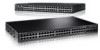
Chapter 1: Dell PowerConnect J-Series J-EX4200 Switches Overview Figure 1: J-EX4200 Switch with 48 Gigabit Ethernet Ports Figure 2: J-EX4200 Switch with 24 Gigabit Ethernet Ports Figure 3: J-EX4200-24F Switch with 24 SFP Ports Related • Chassis Status LEDs in J-EX4200 Switches on page 16 - Dell PowerConnect J-EX4200 | Hardware Guide - Page 24
Dell PowerConnect J-Series J-EX4200 Ethernet Switch Hardware Guide • Management Ethernet port • Console port • ESD point • Power supply or power supplies Figure 4 on page 8 shows the rear panel of a J-EX4200 switch. All J-EX4200 switches have the same rear panel. The 320 W AC power supply is flush - Dell PowerConnect J-EX4200 | Hardware Guide - Page 25
itself. See the information about interfaces and interface naming conventions on J-EX Series Ethernet switches in the multivolume Dell PowerConnect J-Series Ethernet Switch Complete Software Guide for Junos OS at http://www.support.dell.com/ manuals. On a J-EX4200 Virtual Chassis-Member ID of the - Dell PowerConnect J-EX4200 | Hardware Guide - Page 26
Dell PowerConnect J-Series J-EX4200 Ethernet Switch Hardware Guide Table 6: CLI Equivalents of Terms Used in Documentation for the J-EX4200 Switch (continued) Hardware Item (CLI) Description (CLI) Value (CLI Optical transceivers "Optical Interface Support in J-EX4200 Switches" on page 32 Power - Dell PowerConnect J-EX4200 | Hardware Guide - Page 27
to display a custom message, the Menu button and the Enter button are disabled. See the instructions for configuring the LCD panel on J-EX Series switches in the Dell PowerConnect J-Series Ethernet Switch Complete Software Guide for Junos OS: Volume 1 at http://www.support.dell.com/manuals. 11 - Dell PowerConnect J-EX4200 | Hardware Guide - Page 28
interface, you can view real-time status information in the LCD panel. See the information about the dashboard for J-EX Series switches in the Dell PowerConnect J-Series Ethernet Switch Complete Software Guide for Junos OS: Volume 1 at http://www.support.dell.com/manuals for a J-EX4200 switch that is - Dell PowerConnect J-EX4200 | Hardware Guide - Page 29
can use to configure and troubleshoot the switch: • System halt • System reboot • Load rescue • Request VC port (for a switch that is status) • DPX (duplex) • Power over Ethernet (PoE) • SPD (speed) See "Network Port LEDs in J-EX4200 Switches" on page 18 for information on the Status LED - Dell PowerConnect J-EX4200 | Hardware Guide - Page 30
only for a J-EX4200 switch that is a member of a Virtual Chassis configuration. • Press the Menu instructions for configuring the LCD panel on J-EX Series switches in the Dell PowerConnect J-Series Ethernet Switch Complete Software Guide for Junos OS: Volume 1 at http://www.support.dell.com/manuals - Dell PowerConnect J-EX4200 | Hardware Guide - Page 31
menu options. See the instructions for configuring the LCD panel on J-EX Series switches in the Dell PowerConnect J-Series Ethernet Switch Complete Software Guide for Junos OS: Volume 1 at http://www.support.dell.com/manuals. Related • Front Panel of a J-EX4200 Switch on page 6 Documentation - Dell PowerConnect J-EX4200 | Hardware Guide - Page 32
Dell PowerConnect J-Series J-EX4200 Ethernet Switch Hardware Guide Field-Replaceable Units in J-EX4200 Switches Field-replaceable units (FRUs) are components that you can replace at your site. The field-replaceable units (FRUs) in J-EX4200 switches are: • Power supply • Fan tray • Uplink module • - Dell PowerConnect J-EX4200 | Hardware Guide - Page 33
the CLI by issuing the operational mode command show chassis lcd. Table 8: Chassis Status LEDs in a J-EX4200 Switch LED configuration rescue save. For more information, see the Dell PowerConnect J-Series Ethernet Switch Complete Software Guide for Junos OS at http://www.support.dell.com/manuals - Dell PowerConnect J-EX4200 | Hardware Guide - Page 34
alarms, alarm types, and alarm severity levels, see the Dell PowerConnect J-Series Ethernet Switch Complete Software Guide for Junos OS at http://www.support.dell.com/manuals. Network Port LEDs in J-EX4200 Switches Each network port on a J-EX4200 switch has two LEDs. The four figures in this topic - Dell PowerConnect J-EX4200 | Hardware Guide - Page 35
. The port parameters are administrative status, duplex mode, Power over Ethernet (PoE) status, and speed. Table 9 on page 19 describes the Link/Activity LED. Table 9: Link/Activity LED on Network Ports in J-EX4200 Switches LED Color State and Description Link/Activity Green • Blinking-The - Dell PowerConnect J-EX4200 | Hardware Guide - Page 36
Dell PowerConnect J-Series J-EX4200 Ethernet Switch Hardware Guide Table 10: Status LED on Network Ports in J-EX4200 Switches LED LCD Indicator port is the same as the speed at which the uplink module port is configured to operate. • Unlit-The speed of the transceiver installed in the port is - Dell PowerConnect J-EX4200 | Hardware Guide - Page 37
active. Table 12 on page 21 describes the Status LED (administrative status). Table 12: Status LED on the Management Port on J-EX4200 Switches LED Color State and Description Status Green • On steadily-Administrative status is enabled. • Off-Administrative status is disabled. Related • See - Dell PowerConnect J-EX4200 | Hardware Guide - Page 38
Dell PowerConnect J-Series J-EX4200 Ethernet Switch Hardware Guide J-EX4200 switches use power that provides two DC output voltages: 12 V for system and logic power and 48-51 V (or higher, to compensate for voltage drops along - Dell PowerConnect J-EX4200 | Hardware Guide - Page 39
IEEE 802.3af PoE standard. Table 13 on page 23 lists the J-EX4200 power supply ratings and associated PoE power budgets. Starting with Junos OS Release 11.1, a J-EX Series Ethernet switch supports enhanced PoE, a Juniper Networks extension to the IEEE 302.3af PoE standard. Enhanced PoE permits up - Dell PowerConnect J-EX4200 | Hardware Guide - Page 40
Dell PowerConnect J-Series J-EX4200 Ethernet Switch Hardware Guide • Prevention of Electrostatic Discharge Damage on J-EX Series Switches on page 198 • Connecting AC Power to a J-EX4200 Switch on page 117 • Connecting Earth Ground to a J-EX Series Switch on page 115 AC Power Supply LEDs in J- - Dell PowerConnect J-EX4200 | Hardware Guide - Page 41
Switches J-EX4200 switches support the following types of uplink modules: • SFP uplink module-Provides four ports for 1-gigabit small form-factor pluggable (SFP) transceivers. • SFP+ uplink module-Provides two ports for 10-gigabit small form-factor pluggable (SFP+) transceivers when configured - Dell PowerConnect J-EX4200 | Hardware Guide - Page 42
Dell PowerConnect J-Series J-EX4200 Ethernet Switch Hardware Guide 1-gigabit small form-factor pluggable (SFP) transceivers when configured to operate in 1-gigabit mode. NOTE: When a new uplink module is installed in the switch or an existing uplink module is replaced with another uplink module, the - Dell PowerConnect J-EX4200 | Hardware Guide - Page 43
-gigabit operating mode, and for SFP transceivers, you configure the 1-gigabit operating mode. See "Setting the Mode on an SFP+ Uplink Module (CLI Procedure)" on page 135. By default, the SFP+ uplink module operates in the 10-gigabit mode and supports only SFP+ transceivers. If you have not changed - Dell PowerConnect J-EX4200 | Hardware Guide - Page 44
on page 41 • Optical Interface Support in J-EX4200 Switches on page 32 • For information about configuring aggregated Ethernet high-speed uplinks between Virtual Chassis access and distribution switches, see the Dell PowerConnect J-Series Ethernet Switch Complete Software Guide for Junos OS: Volume - Dell PowerConnect J-EX4200 | Hardware Guide - Page 45
Documentation • See Front Panel of a J-EX4500 Switch for port location. • For information about booting the switch from a software package stored on a USB flash drive, see the Dell PowerConnect J-Series Ethernet Switch Complete Software Guide for Junos OS at http://www.support.dell.com/manuals. 29 - Dell PowerConnect J-EX4200 | Hardware Guide - Page 46
Dell PowerConnect J-Series J-EX4200 Ethernet Switch Hardware Guide Network Port Connector Pinout Information for a J-EX4200 Switch A network port on a J-EX4200 switch uses an RJ-45 connector to connect to a device. The port uses an autosensing RJ-45 connector to support a 10/100/1000Base-T - Dell PowerConnect J-EX4200 | Hardware Guide - Page 47
121 Management Port Connector Pinout Information for a J-EX4200 Switch The management port on a J-EX4200 switch uses an RJ-45 connector to connect to a management device for out-of-band management. The port uses an autosensing RJ-45 connector to support a 10/100/1000Base-T connection. Two LEDs on - Dell PowerConnect J-EX4200 | Hardware Guide - Page 48
this manual. For more information, contact Dell. The Gigabit Ethernet SFP or SFP+ transceivers installed in J-EX4200 switches support digital optical monitoring (DOM): you can view the diagnostic details for these transceivers by issuing the operational mode CLI command show interfaces diagnostics - Dell PowerConnect J-EX4200 | Hardware Guide - Page 49
Chapter 3: Component Specifications Table 18: Optical Interface Support and Copper Interface Support for Gigabit Ethernet SFP Transceivers in J-EX4200 Switches Ethernet Standard Specifications 1000Base-T Model Number EX-SFP-1GE-T Rate 10/100/1000 Mbps Connector Type RJ-45 Fiber Count - Dell PowerConnect J-EX4200 | Hardware Guide - Page 50
Dell PowerConnect J-Series J-EX4200 Ethernet Switch Hardware Guide Table 18: Optical Interface Support and Copper Interface Support for Gigabit Ethernet SFP Transceivers in J-EX4200 Switches (continued) Ethernet Standard Specifications 1000Base-SX Model Number EX-SFP-1GE-SX Rate 1000 Mbps - Dell PowerConnect J-EX4200 | Hardware Guide - Page 51
Chapter 3: Component Specifications Table 18: Optical Interface Support and Copper Interface Support for Gigabit Ethernet SFP Transceivers in J-EX4200 Switches (continued) Ethernet Standard Specifications 1000Base-LX Model Number EX-SFP-1GE-LX Rate 1000 Mbps Connector Type LC Fiber Count - Dell PowerConnect J-EX4200 | Hardware Guide - Page 52
Dell PowerConnect J-Series J-EX4200 Ethernet Switch Hardware Guide Table 18: Optical Interface Support and Copper Interface Support for Gigabit Ethernet SFP Transceivers in J-EX4200 Switches (continued) Ethernet Standard Specifications 1000Base-LX Model Number EX-SFP-1GE-LX40K Rate 1000 Mbps - Dell PowerConnect J-EX4200 | Hardware Guide - Page 53
Chapter 3: Component Specifications Table 18: Optical Interface Support and Copper Interface Support for Gigabit Ethernet SFP Transceivers in J-EX4200 Switches (continued) Ethernet Standard Specifications 1000Base-LH (or 1000Base-ZX) Model Number Rate EX-SFP-1GE-LH 1000 Mbps Connector Type - Dell PowerConnect J-EX4200 | Hardware Guide - Page 54
Dell PowerConnect J-Series J-EX4200 Ethernet Switch Hardware Guide Table 19: Optical Interface Support for Fast Ethernet SFP Transceivers in J-EX4200 Switches Ethernet Standard Specifications 100Base-FX Model Number EX-SFP-1FE-FX Rate 100 Mbps Connector Type LC Fiber Count Dual - Dell PowerConnect J-EX4200 | Hardware Guide - Page 55
Chapter 3: Component Specifications Table 20: Optical Interface Support for Gigabit Ethernet SFP+ Transceivers in J-EX4200 Switches Ethernet Standard Specifications 10GBase-SR Model Number EX-SFP-10GE-SR Rate 10 Gbps Connector Type LC Fiber Count Dual Transmitter Wavelength 850 nm - Dell PowerConnect J-EX4200 | Hardware Guide - Page 56
Dell PowerConnect J-Series J-EX4200 Ethernet Switch Hardware Guide Table 20: Optical Interface Support for Gigabit Ethernet SFP+ Transceivers in J-EX4200 Switches (continued) Ethernet Standard Specifications 10GBase-LRM Model Number EX-SFP-10GE-LRM Rate 10 Gbps Connector Type LC Fiber - Dell PowerConnect J-EX4200 | Hardware Guide - Page 57
• Uplink Modules in J-EX4200 Switches on page 25 • For show interfaces diagnostics optics command syntax, see the Dell PowerConnect J-Series Ethernet Switch Complete Software Guide for Junos OS at http://www.support.dell.com/manuals. • Installing a Transceiver in a J-EX Series Switch on page 110 - Dell PowerConnect J-EX4200 | Hardware Guide - Page 58
Dell PowerConnect J-Series J-EX4200 Ethernet Switch Hardware Guide NOTE: You can use these ports to connect an access switch to a distribution switch. You can also use optional uplink module ports to connect members of a Virtual Chassis across multiple wiring closets. Table 21: Uplink Modules - Dell PowerConnect J-EX4200 | Hardware Guide - Page 59
Chapter 3: Component Specifications Table 21: Uplink Modules Connector Pinout Information for J-EX4200 Switches (continued) Pin Number Pin Name B2 XAUI0_RX0N B3 GND B4 XAUI0_RX2N B5 Uplink_P25_LED2 B6 XAUI1_RX0N B7 Uplink_P27_LED2 B8 XAUI1_RX2N B9 GND B10 SRX28N B11 - Dell PowerConnect J-EX4200 | Hardware Guide - Page 60
Dell PowerConnect J-Series J-EX4200 Ethernet Switch Hardware Guide Table 21: Uplink Modules Connector Pinout Information for J-EX4200 Switches (continued) Pin Number Pin Name C6 XAUI1_RX0P C7 GND C8 XAUI1_RX2P C9 GND C10 SRX28P C11 GND C12 SRX26P C13 GND C14 SGMIIRXP C15 - Dell PowerConnect J-EX4200 | Hardware Guide - Page 61
Chapter 3: Component Specifications Table 21: Uplink Modules Connector Pinout Information for J-EX4200 Switches (continued) Pin Number Pin Name D10 GND D11 STX27N D12 GND D13 STX25N D14 GND D15 Uplink_Rst D16 GND D17 Uplink_Status_LED0 D18 GND D19 POWER ( - Dell PowerConnect J-EX4200 | Hardware Guide - Page 62
Dell PowerConnect J-Series J-EX4200 Ethernet Switch Hardware Guide Table 21: Uplink Modules Connector Pinout Information for J-EX4200 Switches (continued) Pin Number Pin Name E14 SGMIITXN E15 Uplink_Hotswap_LED E16 Uplink_Spare_Intr E17 Uplink_Status_LED1 E18 Uplink_P27_LED0 E19 POWER - Dell PowerConnect J-EX4200 | Hardware Guide - Page 63
Chapter 3: Component Specifications Table 21: Uplink Modules Connector Pinout Information for J-EX4200 Switches (continued) Pin Number Pin Name F18 Uplink_P27_LED1 F19 GND F20 POWER (12V) G1 GND G2 GND G3 XAUI0_RX1N G4 GND G5 XAUI0_RX3N G6 GND G7 - Dell PowerConnect J-EX4200 | Hardware Guide - Page 64
Dell PowerConnect J-Series J-EX4200 Ethernet Switch Hardware Guide Table 21: Uplink Modules Connector Pinout Information for J-EX4200 Switches (continued) Pin Number Pin Name H2 GND H3 XAUI0_RX1P H4 GND H5 XAUI0_RX3P H6 Uplink_P26_ LED2 H7 XAUI1_RX1P H8 Uplink_P28_ LED2 H9 - Dell PowerConnect J-EX4200 | Hardware Guide - Page 65
Documentation • Front Panel of a J-EX4200 Switch on page 6 • Installing an Uplink Module in a J-EX4200 Switch on page 108 • Removing an Uplink Module from a J-EX4200 Switch on page 142 Virtual Chassis Ports Connector Pinout Information for J-EX4200 Switches J-EX4200 switches use a 68-pin connector - Dell PowerConnect J-EX4200 | Hardware Guide - Page 66
Dell PowerConnect J-Series J-EX4200 Ethernet Switch Hardware Guide Table 22: Virtual Chassis Ports (VCPs) Connector Pinout Information Pin Number Pin Name A1 GND A2 P1TXP0 A3 P1TXN0 A4 GND A5 P1TXP1 A6 P1TXN1 - Dell PowerConnect J-EX4200 | Hardware Guide - Page 67
Chapter 3: Component Specifications Table 22: Virtual Chassis Ports (VCPs) Connector Pinout Information (continued) Pin Number Pin Name A25 GND A26 P2TXP1 A27 P2TXN1 A28 GND A29 P2TXP2 A30 P2TXN2 A31 GND A32 P2TXP3 A33 P2TXN3 A34 GND B1 GND B2 P1RXP0 B3 P1RXN0 B4 GND - Dell PowerConnect J-EX4200 | Hardware Guide - Page 68
Cabling Configuration Examples for J-EX4200 Switches on page 77 Documentation • Planning the Virtual Chassis on page 76 • For information about Virtual Chassis components, see the Dell PowerConnect J-Series Ethernet Switch Complete Software Guide for Junos OS at http://www.support.dell.com/manuals - Dell PowerConnect J-EX4200 | Hardware Guide - Page 69
Chapter 3: Component Specifications • Understanding Virtual Chassis Hardware Configuration on a J-EX4200 Switch on page 75 • Connecting a Virtual Chassis Cable to a J-EX4200 Switch on page 112 53 - Dell PowerConnect J-EX4200 | Hardware Guide - Page 70
Dell PowerConnect J-Series J-EX4200 Ethernet Switch Hardware Guide 54 - Dell PowerConnect J-EX4200 | Hardware Guide - Page 71
PART 2 Planning for Switch Installation • Site Preparation on page 57 • Mounting and Clearance Requirements on page 63 • Cable Specifications on page 69 • Planning Power Requirements on page 71 • Planning the Virtual Chassis on page 75 55 - Dell PowerConnect J-EX4200 | Hardware Guide - Page 72
Dell PowerConnect J-Series J-EX4200 Ethernet Switch Hardware Guide 56 - Dell PowerConnect J-EX4200 | Hardware Guide - Page 73
for connection of system grounding. Calculate the power consumption and requirements. "Power Specifications for J-EX4200 Switches" on page 71 Hardware Configuration Choose the number and types of switches you want to install. "J-EX4200 Switches Hardware Overview" on page 3 Rack or Cabinet 57 - Dell PowerConnect J-EX4200 | Hardware Guide - Page 74
Dell PowerConnect J-Series J-EX4200 Ethernet Switch Hardware Guide Table 23: Site Preparation Checklist (continued) Item or Task For More Information Performed By Date Verify that your rack or cabinet meets the minimum requirements for the installation of the switch. "Rack Requirements for J- - Dell PowerConnect J-EX4200 | Hardware Guide - Page 75
EX4200 Switches on page 66 • Environmental Requirements and Specifications for J-EX Series Switches on page 60 Site Electrical Wiring Guidelines for J-EX Series Switches Guidelines If your site experiences any of the following problems, consult experts in electrical surge suppression and shielding: - Dell PowerConnect J-EX4200 | Hardware Guide - Page 76
Dell PowerConnect J-Series J-EX4200 Ethernet Switch Hardware Guide Table 24: Site Electrical Wiring Guidelines (continued for each data signal when applicable. If your site is susceptible to problems with electromagnetic compatibility (EMC), particularly from lightning or radio transmitters, seek - Dell PowerConnect J-EX4200 | Hardware Guide - Page 77
with Zone 4 earthquake requirements as per GR-63, Issue 3. NOTE: Install J-EX Series switches only in restricted areas, such as dedicated equipment rooms and equipment closets, in accordance with Articles for Airflow and Hardware Maintenance for J-EX4200 Switches Documentation on page 66 61 - Dell PowerConnect J-EX4200 | Hardware Guide - Page 78
Dell PowerConnect J-Series J-EX4200 Ethernet Switch Hardware Guide 62 - Dell PowerConnect J-EX4200 | Hardware Guide - Page 79
Airflow and Hardware Maintenance for J-EX4200 Switches on page 66 Rack Requirements for J-EX4200 Switches You can mount the switch on two-post racks or (http://www.eia.org). The rack must meet the strength requirements to support the weight of the chassis. Mounting bracket hole The holes in the - Dell PowerConnect J-EX4200 | Hardware Guide - Page 80
Dell PowerConnect J-Series J-EX4200 Ethernet Switch Hardware Guide Table 26: Rack Requirements and Specifications for the Switch (continued) Rack cm). • The rack must be strong enough to support the weight of the switch. A fully configured J-EX4200 switch weighs up to 22 lb (10 kg). If you mount - Dell PowerConnect J-EX4200 | Hardware Guide - Page 81
number EIA-310-D) published by the Electronics Industry Association (http://www.eia.org). NOTE: The rack must meet the strength requirements to support the weight of the switch. A fully configured J-EX4200 switch weighs up to 22 lb (10 kg). If you mount multiple units in one rack, that rack must - Dell PowerConnect J-EX4200 | Hardware Guide - Page 82
Dell PowerConnect J-Series J-EX4200 Ethernet Switch Hardware Guide Requirements for Mounting a J-EX4200 Switch on a Desktop or Wall You can install the switch the wall onto which the switch is installed is stable and securely supported. If you are mounting the switch in sheetrock (wall board with - Dell PowerConnect J-EX4200 | Hardware Guide - Page 83
equipment does not blow into the intake vents of the chassis. • Leave at least 24 in. (61 cm) both in front of and behind the J-EX4200 switch. For service personnel to remove and install hardware components, you must leave adequate space at the front and back of the - Dell PowerConnect J-EX4200 | Hardware Guide - Page 84
Dell PowerConnect J-Series J-EX4200 Ethernet Switch Hardware Guide 68 - Dell PowerConnect J-EX4200 | Hardware Guide - Page 85
on page 69 Network Cable Specifications for J-EX4200 Switches J-EX4200 switches have interfaces that use various types of network cables. For instructions on connecting a J-EX4200 switch to a network for out-of-band management using an Ethernet cable with an RJ-45 connector, see "Connecting a J-EX - Dell PowerConnect J-EX4200 | Hardware Guide - Page 86
Dell PowerConnect J-Series J-EX4200 Ethernet Switch Hardware Guide 70 - Dell PowerConnect J-EX4200 | Hardware Guide - Page 87
system current rating 4 A (for switches with 8 ports equipped for Power over Ethernet (PoE) or the switch with 24 100Base-FX/1000Base-SX SFP ports) Related • AC Power Cord Specifications for J-EX4200 Switches on page 71 Documentation • Power Supply in J-EX4200 Switches on page 21 • General Safety - Dell PowerConnect J-EX4200 | Hardware Guide - Page 88
Dell PowerConnect J-Series J-EX4200 Ethernet Switch Hardware Guide International Electrotechnical Commission (IEC) standard 60320. The plug at the male end of the power cord fits into the power source outlet that is standard - Dell PowerConnect J-EX4200 | Hardware Guide - Page 89
of the countries and regions listed in Table 29 on page 72. Figure 19: AC Plug Types Related • Power Supply in J-EX4200 Switches on page 21 Documentation • General Safety Guidelines and Warnings for J-EX Series Switches on page 171 • General Electrical Safety Guidelines and Warnings for J-EX Series - Dell PowerConnect J-EX4200 | Hardware Guide - Page 90
Dell PowerConnect J-Series J-EX4200 Ethernet Switch Hardware Guide 74 - Dell PowerConnect J-EX4200 | Hardware Guide - Page 91
Dell PowerConnect J-Series Ethernet Switch Complete Software Guide for Junos OS at http://www.support.dell.com/manuals. • Planning the Virtual Chassis on page 76 • Virtual Chassis Ports Connector Pinout Information for J-EX4200 Switches on page 49 • Virtual Chassis Cabling Configuration Examples - Dell PowerConnect J-EX4200 | Hardware Guide - Page 92
weights and dimensions, see the Dell PowerConnect J-Series J-EX4500 Ethernet Switch Hardware Guide at http://www.support.dell.com/manuals. • Cabling Requirements for Virtual Chassis.You can interconnect the J-EX4200 switches in a Virtual Chassis configuration through Virtual Chassis ports (VCPs - Dell PowerConnect J-EX4200 | Hardware Guide - Page 93
the uplink module ports as VCP interfaces. See the instructions for setting an uplink module as a Virtual Chassis port in the Dell PowerConnect J-Series Ethernet Switch Complete Software Guide for Junos OS at http://www.support.dell.com/manuals. NOTE: The interfaces for the two dedicated VCPs are - Dell PowerConnect J-EX4200 | Hardware Guide - Page 94
Dell PowerConnect J-Series J-EX4200 Ethernet Switch Hardware Guide Figure 20: J-EX4200 Switches Mounted on a Single Rack and Connected in a Ring Topology Using Short and Long Cables: Option 1 Figure 21: J-EX4200 Switches Mounted on a Single Rack and Connected in a Ring Topology Using Short and Long - Dell PowerConnect J-EX4200 | Hardware Guide - Page 95
a J-EX4200 Switch on Documentation page 75 • For information about Virtual Chassis components and an example of Virtual Chassis configuration across multiple wiring closets, see the Dell PowerConnect J-Series Ethernet Switch Complete Software Guide for Junos OS at http://www.support.dell.com/manuals - Dell PowerConnect J-EX4200 | Hardware Guide - Page 96
defaults. For information about reverting to the factory default configuration, see the Dell PowerConnect J-Series Ethernet Switch Complete Software Guide for Junos OS at http://www.support.dell.com/manuals. 2. Interconnect the unpowered new switch to at least one member of the existing Virtual - Dell PowerConnect J-EX4200 | Hardware Guide - Page 97
information about reverting to the factory default configuration, see the Dell PowerConnect J-Series Ethernet Switch Complete Software Guide for Junos OS at http://www.support.dell.com/manuals. • Powered on the new member switch as a standalone switch and configured its uplink module ports as VCPs - Dell PowerConnect J-EX4200 | Hardware Guide - Page 98
active master. For information about configuring a Virtual Chassis with a preprovisioned configuration file, see the Dell PowerConnect J-Series Ethernet Switch Complete Software Guide for Junos OS at http://www.support.dell.com/manuals. • On the master, configured the Link Level Discovery Protocol - Dell PowerConnect J-EX4200 | Hardware Guide - Page 99
• Replacing a Member Switch of a Virtual Chassis Configuration (CLI Procedure) on Documentation page 148 • For more information about Virtual Chassis configuration, see the Dell PowerConnect J-Series Ethernet Switch Complete Software Guide for Junos OS at http://www.support.dell.com/manuals. 83 - Dell PowerConnect J-EX4200 | Hardware Guide - Page 100
Dell PowerConnect J-Series J-EX4200 Ethernet Switch Hardware Guide 84 - Dell PowerConnect J-EX4200 | Hardware Guide - Page 101
PART 3 Installing and Connecting the Switch and Switch Components • Installing the Switch on page 87 • Installing Switch Components on page 105 • Connecting the Switch on page 115 • Performing Initial Configuration on page 127 85 - Dell PowerConnect J-EX4200 | Hardware Guide - Page 102
Dell PowerConnect J-Series J-EX4200 Ethernet Switch Hardware Guide 86 - Dell PowerConnect J-EX4200 | Hardware Guide - Page 103
that houses the hardware components. To install and connect a J-EX4200 switch: 1. Follow instructions in "Unpacking a J-EX4200 Switch" on page 88. 2. Mount the switch by following instructions appropriate for your site: • "Mounting a J-EX4200 Switch on Two Posts in a Rack or Cabinet" on page 92 - Dell PowerConnect J-EX4200 | Hardware Guide - Page 104
Dell PowerConnect J-Series J-EX4200 Ethernet Switch Hardware Guide 4. Follow instructions for connecting power as appropriate for your site: • Connecting AC Power to a J-EX4200 Switch on page 117 5. Perform initial configuration of the switch by following instructions in "Connecting and Configuring - Dell PowerConnect J-EX4200 | Hardware Guide - Page 105
, see "Contacting Dell" on page 165. 7. Save the shipping carton and packing materials in case you need to move or ship the switch later. Figure 25: Unpacking a J-EX4200 Switch Table 30: Inventory of Components Provided with a J-EX4200 Switch Component Quantity Switch 1 Fan tray (preinstalled - Dell PowerConnect J-EX4200 | Hardware Guide - Page 106
2 Dust covers for ports (for a J-EX4200-24F switch) 24 Quick Start installation instructions 1 Dell PowerConnect Safety, Environmental, and Regulatory Information 1 End User License Agreement 1 DellPowerConnect Warranty and Support Information 1 Registration and Software Updates for Your - Dell PowerConnect J-EX4200 | Hardware Guide - Page 107
parts and tools available: • 4 rubber feet to stabilize the chassis on the a desk or other level surface (provided in the accessory box shipped with the switch) • Dust covers for ports (for J-EX4200-24F switches only; optional) To mount the switch on a desk or other level surface: 91 - Dell PowerConnect J-EX4200 | Hardware Guide - Page 108
Dell PowerConnect J-Series J-EX4200 Ethernet Switch Hardware Guide 1. Turn the chassis upside down on the desk or the level surface where you intend to mount the switch. 2. Attach the rubber feet to the bottom of the chassis, as shown in Figure 26 on page 92. 3. Turn the chassis right side up on - Dell PowerConnect J-EX4200 | Hardware Guide - Page 109
rack-mount kit). • Dust covers for ports (for J-EX4200-24F switches only; optional) NOTE: One person must be available to lift the switch while another secures the switch to the rack. CAUTION: If you are mounting multiple switches on a rack, mount a switch in the bottom of the rack first and proceed - Dell PowerConnect J-EX4200 | Hardware Guide - Page 110
g040637 g040639 Dell PowerConnect J-Series J-EX4200 Ethernet Switch Hardware Guide Figure 27: Installing a Round-Hole Cage Nut (Clip Nut) Figure 28: Installing a Square-Hole Cage Nut b. To ensure that the switch chassis is level after installation, verify that the cage nuts on one side of the rack - Dell PowerConnect J-EX4200 | Hardware Guide - Page 111
. If the switch is a J-EX4200-24F model, we recommend that you insert dust covers in any unused SFP ports. Related • Connecting Earth Ground to a J-EX Series Switch on page 115 Documentation • Connecting AC Power to a J-EX4200 Switch on page 117 • Connecting and Configuring a J-EX Series Switch (CLI - Dell PowerConnect J-EX4200 | Hardware Guide - Page 112
Dell PowerConnect J-Series J-EX4200 Ethernet Switch Hardware Guide Mounting a J-EX4200 Switch on Four Posts in a Rack or Cabinet You can mount a J-EX4200 switch on four posts of a 19-in. rack or cabinet by using the separately orderable four-post rack-mount kit. (The remainder of this topic uses " - Dell PowerConnect J-EX4200 | Hardware Guide - Page 113
nuts and washers if your rack requires them-to secure the chassis and the rear brackets to the rack (provided) • Dust covers for ports (for J-EX4200-24F switches only; optional) CAUTION: If you are mounting multiple units on a rack, mount the heaviest unit at the bottom of the rack and mount the - Dell PowerConnect J-EX4200 | Hardware Guide - Page 114
Dell PowerConnect J-Series J-EX4200 Ethernet Switch Hardware Guide Figure 33: Attaching the Front Bracket to the Side-Rail Bracket 3. Place the switch on a flat, stable surface. 4. Align the side-rail brackets along the side panels of the switch chassis. Align the two holes in the rear of the side- - Dell PowerConnect J-EX4200 | Hardware Guide - Page 115
bracket 8. Have a second person secure the front of the switch to the rack with the appropriate hardware for your rack: Figure 36: Sliding the Rear Brackets to the Rear of a Four-Post Rack Rear brackets Switch g004478 Side-rail bracket 10. Attach the rear brackets to the rear post by using the - Dell PowerConnect J-EX4200 | Hardware Guide - Page 116
Dell PowerConnect J-Series J-EX4200 Ethernet Switch Hardware Guide 11. Tighten the screws. 12. Ensure that the switch chassis is level by verifying that all the screws on the front of the rack are aligned with the screws at the back of the rack. 13. If the switch is a J-EX4200-24F model, we - Dell PowerConnect J-EX4200 | Hardware Guide - Page 117
-mount kit) • 4 mounting screws (8-32 x 1.25 in. or M4 x 30 mm) (not included) • Dust covers for ports (for J-EX4200-24F switches only; optional) • Hollow wall anchors capable of supporting the combined weight of two fully loaded switches, up to 44 lb (20 kg) (not included)-if you are mounting the - Dell PowerConnect J-EX4200 | Hardware Guide - Page 118
g020200 Dell PowerConnect J-Series J-EX4200 Ethernet Switch Hardware Guide 1. Attach the wall-mount brackets to the sides of the chassis using four of the wall-mount bracket screws on each side, as shown in Figure 37 on page 102. Figure 37: Attaching Wall-Mount Brackets to a J-EX4200 Switch Chassis - Dell PowerConnect J-EX4200 | Hardware Guide - Page 119
5. Tighten the mounting screws. 6. If it is a J-EX4200-24F switch, we recommend you insert dust covers in unused SFP ports. Related • Connecting AC Power to a J-EX4200 Switch on page 117 Documentation • Connecting and Configuring a J-EX Series Switch (CLI Procedure) on page 131 • Connecting and - Dell PowerConnect J-EX4200 | Hardware Guide - Page 120
Dell PowerConnect J-Series J-EX4200 Ethernet Switch Hardware Guide 104 - Dell PowerConnect J-EX4200 | Hardware Guide - Page 121
"Installing a Power Supply in a J-EX4200 Switch" on page 106. To remove a power supply, follow instructions in "Removing a Power Supply from a J-EX4200 Switch" on page 140. To install a fan tray in a J-EX4200 switch, follow instructions in "Installing a Fan Tray in a J-EX4200 Switch" on page 107. To - Dell PowerConnect J-EX4200 | Hardware Guide - Page 122
Dell PowerConnect J-Series J-EX4200 Ethernet Switch Hardware Guide To install an SFP or SFP+ transceiver in a J-EX4200 switch, follow instructions in "Installing a Transceiver in a J-EX Series Switch" on page 110. To remove a transceiver, follow instructions in "Removing a Transceiver from a J-EX - Dell PowerConnect J-EX4200 | Hardware Guide - Page 123
105 • Power Supply in J-EX4200 Switches on page 21 • Field-Replaceable Units in J-EX4200 Switches on page 16 • AC Power Cord Specifications for J-EX4200 Switches on page 71 • Rear Panel of a J-EX4200 Switch on page 7 Installing a Fan Tray in a J-EX4200 Switch J-EX4200 switches have a single fan tray - Dell PowerConnect J-EX4200 | Hardware Guide - Page 124
replace the module. See the instructions for setting an uplink module port as a VCP in the Dell PowerConnect J-Series Ethernet Switch Complete Software Guide for Junos OS at http://www.support.dell.com/manuals. Before you begin installing an uplink module in a J-EX4200 switch: • Ensure that you have - Dell PowerConnect J-EX4200 | Hardware Guide - Page 125
same uplink module. If you do not wait for at least 10 seconds, the interfaces on the uplink module might not come up. 3. Taking care not to touch : If the switch does not detect the uplink module, see "Troubleshooting Uplink Module Installation or Replacement on J-EX4200 Switches" on page 158. 109 - Dell PowerConnect J-EX4200 | Hardware Guide - Page 126
on page 105 • For information about configuring Gigabith Ethernet interfaces on the switch, see the Dell PowerConnect J-Series Ethernet Switch Complete Software Guide for Junos OS at http://www.support.dell.com/manuals. • Front Panel of a J-EX4200 Switch on page 6 Installing a Transceiver in a J-EX - Dell PowerConnect J-EX4200 | Hardware Guide - Page 127
the port before installing a transceiver. 4. Using both hands, carefully place the transceiver in the empty port. The connectors must face the switch chassis. CAUTION: Before you slide the transceiver into the port, ensure the transceiver is aligned correctly. Misalignment might cause the pins to - Dell PowerConnect J-EX4200 | Hardware Guide - Page 128
Dell PowerConnect J-Series J-EX4200 Ethernet Switch Hardware Guide Related • Removing a Transceiver from a J-EX Series Switch on page 144 Documentation • Connecting a Fiber-Optic Cable to a J-EX Series Switch on page 125 • Optical Interface Support in J-EX4200 Switches on page 32 Connecting a - Dell PowerConnect J-EX4200 | Hardware Guide - Page 129
• Understanding Virtual Chassis Hardware Configuration on a J-EX4200 Switch on page 75 • For information about Virtual Chassis components, see the Dell PowerConnect J-Series Ethernet Switch Complete Software Guide for Junos OS at http://www.support.dell.com/manuals. • Planning the Virtual Chassis - Dell PowerConnect J-EX4200 | Hardware Guide - Page 130
Dell PowerConnect J-Series J-EX4200 Ethernet Switch Hardware Guide 114 - Dell PowerConnect J-EX4200 | Hardware Guide - Page 131
on page 115 • Connecting AC Power to a J-EX4200 Switch on page 117 • Connecting a J-EX Series Switch to a Network for Out-of-Band Management on page 120 • Connecting a J-EX Series Switch to a Management Console on page 121 • Connecting a J-EX Series Switch to a Modem on page 122 • Connecting a Fiber - Dell PowerConnect J-EX4200 | Hardware Guide - Page 132
Dell PowerConnect J-Series J-EX4200 Ethernet Switch Hardware Guide CAUTION: Using a grounding cable with an incorrectly attached lug can damage the switch. Follow the procedure that applies to your switch: • Connecting Earth Ground to a J-EX4200 Switch on page 116 Connecting Earth Ground to a J- - Dell PowerConnect J-EX4200 | Hardware Guide - Page 133
unit (FRU) located on the rear panel: You can remove and replace it without powering off the switch or disrupting switch functions. Before you begin connecting AC power to a J-EX4200 switch: • Ensure that you have connected the switch chassis to earth ground. CAUTION: Before you connect power to the - Dell PowerConnect J-EX4200 | Hardware Guide - Page 134
Dell PowerConnect J-Series J-EX4200 Ethernet Switch Hardware Guide To meet safety and electromagnetic interference (EMI) requirements and to ensure proper operation, you must connect J-EX4200 switches to earth ground before you connect them to power. For installations that require a separate - Dell PowerConnect J-EX4200 | Hardware Guide - Page 135
Cord to an AC Power Supply in a J-EX4200 Switch Related • Connecting and Configuring a J-EX Series Switch (CLI Procedure) on page 131 Documentation • Connecting and Configuring a J-EX Series Switch (J-Web Procedure) on page 133 • Power Supply in J-EX4200 Switches on page 21 • AC Power Supply LEDs - Dell PowerConnect J-EX4200 | Hardware Guide - Page 136
Dell PowerConnect J-Series J-EX4200 Ethernet Switch Hardware Guide Connecting a J-EX Series Switch to a Network for Out-of-Band Management You can monitor and manage a J-EX Series switch using a dedicated management channel. J-EX Series switches have a management port with an RJ-45 connector for out - Dell PowerConnect J-EX4200 | Hardware Guide - Page 137
a J-EX4200 Switch" on page 7. 2. Connect the other end of the Ethernet cable into the console server (see Figure 51 on page 121) or management console (see Figure 52 on page 122). To configure the switch from the management console, see"Connecting and Configuring a J-EX Series Switch (CLI Procedure - Dell PowerConnect J-EX4200 | Hardware Guide - Page 138
Dell PowerConnect J-Series J-EX4200 Ethernet Switch Hardware Guide Figure 52: Connecting a J-EX Series Switch Directly to a Management Console Related • Connecting a J-EX Series Switch to a Network for Out-of-Band Management on page 120 Documentation • Console Port Connector Pinout Information for a - Dell PowerConnect J-EX4200 | Hardware Guide - Page 139
baudrate=115200 Press Enter. 4. Press Enter when you see the following message: Switch baud rate to 115200 bps and press Enter. The loader> prompt reappears. 5. the documentation for your modem for the equivalent modem commands. To configure the modem: 1. Connect the modem to the desktop or notebook - Dell PowerConnect J-EX4200 | Hardware Guide - Page 140
Dell PowerConnect J-Series J-EX4200 Ethernet Switch Hardware Guide Table 31: Port Settings Port Settings Bits per desktop or notebook computer. 6. To configure the modem to answer a call on the first ring, type ats0=1 at the prompt. Press Enter. 7. To configure the modem to accept modem-control DTR - Dell PowerConnect J-EX4200 | Hardware Guide - Page 141
to DB-9 adapter and Ethernet cable supplied with the switch. To connect a modem to the console port: 1. Turn off power to the switch. 2. Turn off power (labeled CON or CONSOLE) on the switch. For the location of the console port, see "Rear Panel of a J-EX4200 Switch" on page 7. 4. Connect the other - Dell PowerConnect J-EX4200 | Hardware Guide - Page 142
g027016 Dell PowerConnect J-Series J-EX4200 Ethernet Switch Hardware Guide To connect a fiber-optic cable to an optical transceiver installed in a J-EX Series switch: WARNING: Do not look directly into a fiber-optic transceiver or into the ends of fiber-optic cables. Fiber-optic transceivers and - Dell PowerConnect J-EX4200 | Hardware Guide - Page 143
always revert to the factory default configuration. For instructions, see the Dell PowerConnect J-Series Ethernet Switch Complete Software Guide for Junos OS at http://www.support.dell.com/manuals. The following factory default configuration file is for a J-EX4200 switch with 24 ports (for models - Dell PowerConnect J-EX4200 | Hardware Guide - Page 144
Dell PowerConnect J-Series J-EX4200 Ethernet Switch Hardware Guide interactive-commands any; } } commit { factory-settings { reset-chassis-lcd-menu; reset-virtual-chassis-configuration; } } } interfaces { ge-0/0/0 { unit 0 { family ethernet-switching; } } ge-0/0/1 { unit 0 { family ethernet- - Dell PowerConnect J-EX4200 | Hardware Guide - Page 145
family ethernet-switching; } } ge-0/0/16 { unit 0 { family ethernet-switching; } } ge-0/0/17 { unit 0 { family ethernet-switching; } } ge-0/0/18 { unit 0 { family ethernet-switching; } } ge-0/0/19 { unit 0 { family ethernet-switching; } } ge-0/0/20 { Chapter 12: Performing Initial Configuration 129 - Dell PowerConnect J-EX4200 | Hardware Guide - Page 146
Dell PowerConnect J-Series J-EX4200 Ethernet Switch Hardware Guide unit 0 { family ethernet-switching; } } ge-0/0/21 { unit 0 { family ethernet-switching; } } ge-0/0/22 { unit 0 { family ethernet-switching; } } ge-0/0/23 { unit 0 { family ethernet-switching; } } xe-0/1/0 { unit 0 { family ethernet- - Dell PowerConnect J-EX4200 | Hardware Guide - Page 147
Series switch configuration files and interfaces and instructions for reverting to the factory default configuration, see the Dell PowerConnect J-Series Ethernet Switch Complete Software Guide for Junos OS at http://www.support.dell.com/manuals. Connecting and Configuring a J-EX Series Switch (CLI - Dell PowerConnect J-EX4200 | Hardware Guide - Page 148
Dell PowerConnect J-Series J-EX4200 Ethernet Switch Hardware Guide • Stop Bits-1 • DCD State-Disregard To connect and configure the switch from the console: 1. Connect the console port on the rear panel of the switch to a laptop or PC using the RJ-45 to DB-9 serial port adapter. The RJ-45 cable and - Dell PowerConnect J-EX4200 | Hardware Guide - Page 149
setup mode. To connect and configure the switch using the J-Web interface: 1. To transition the switch into initial setup mode, use the Menu and Enter buttons located to the right of the LCD panel (see Figure 55 on page 133): Figure 55: LCD Panel in a J-EX4200 Switch a. Press the Menu button until - Dell PowerConnect J-EX4200 | Hardware Guide - Page 150
Dell PowerConnect J-Series J-EX4200 Ethernet Switch Hardware Guide settings of the switch with the management PC or set them manually by selecting the interface. 9. Click Next. 10. On the Manage Access page, you may select options to enable Telnet, SSH, and SNMP services. For SNMP, you can configure - Dell PowerConnect J-EX4200 | Hardware Guide - Page 151
address. If the connection cannot be made, the J-Web interface displays instructions for starting a J-Web session. Related • Connecting and Configuring a J-EX Series Switch (CLI Procedure) on page 131 Documentation • Installing and Connecting a J-EX4200 Switch on page 87 Setting the Mode on an SFP - Dell PowerConnect J-EX4200 | Hardware Guide - Page 152
Dell PowerConnect J-Series J-EX4200 Ethernet Switch Hardware Guide 136 - Dell PowerConnect J-EX4200 | Hardware Guide - Page 153
PART 4 Removing Switch Components • Removing Switch Components on page 139 137 - Dell PowerConnect J-EX4200 | Hardware Guide - Page 154
Dell PowerConnect J-Series J-EX4200 Ethernet Switch Hardware Guide 138 - Dell PowerConnect J-EX4200 | Hardware Guide - Page 155
a Virtual Chassis Cable from a J-EX4200 Switch on page 147 • Replacing a Member Switch of a Virtual Chassis Configuration (CLI Procedure) on page 148 • Removing a Cage Nut from a Rack on page 150 Installing and Removing J-EX4200 Switch Hardware Components The J-EX4200 switch chassis is a rigid sheet - Dell PowerConnect J-EX4200 | Hardware Guide - Page 156
Dell PowerConnect J-Series J-EX4200 Ethernet Switch Hardware Guide To install an uplink module in a J-EX4200 switch, follow instructions in "Installing an Uplink Module in a J-EX4200 Switch" on page 108. To remove an uplink module, follow instructions in "Removing an Uplink Module from a J-EX4200 - Dell PowerConnect J-EX4200 | Hardware Guide - Page 157
105 • Power Supply in J-EX4200 Switches on page 21 • Field-Replaceable Units in J-EX4200 Switches on page 16 • AC Power Cord Specifications for J-EX4200 Switches on page 71 • Rear Panel of a J-EX4200 Switch on page 7 Removing a Fan Tray from a J-EX4200 Switch J-EX4200 switches have a single fan tray - Dell PowerConnect J-EX4200 | Hardware Guide - Page 158
Dell PowerConnect J-Series J-EX4200 Ethernet Switch Hardware Guide WARNING: To avoid injury, do not touch the fan with your hands or any tools as you slide the fan tray out of the chassis- - Dell PowerConnect J-EX4200 | Hardware Guide - Page 159
port as a VCP after you replace the module. For instructions, see the Dell PowerConnect J-Series Ethernet Switch Complete Software Guide for Junos OS at http://www.support.dell.com/manuals. Before you begin removing an uplink module from a J-EX4200 switch: • Ensure that you have taken the necessary - Dell PowerConnect J-EX4200 | Hardware Guide - Page 160
Dell PowerConnect J-Series J-EX4200 Ethernet Switch Hardware Guide 6. Slide the screwdriver out of the keyhole. 7. Place the uplink module in an antistatic bag or on an antistatic mat placed on a flat, stable surface. - Dell PowerConnect J-EX4200 | Hardware Guide - Page 161
arc smaller than a few inches in diameter can damage the cables and cause problems that are difficult to diagnose. 3. Remove the cable connected to the transceiver (see "Disconnecting a Fiber-Optic Cable from a J-EX Series Switch" on page 146). Cover the transceiver and the end of each fiber-optic - Dell PowerConnect J-EX4200 | Hardware Guide - Page 162
Dell PowerConnect J-Series J-EX4200 Ethernet Switch Hardware Guide 6. Grasp the transceiver ejector lever and gently a J-EX Series Switch Related • Installing a Transceiver in a J-EX Series Switch on page 110 Documentation • Optical Interface Support in J-EX4200 Switches on page 32 Disconnecting - Dell PowerConnect J-EX4200 | Hardware Guide - Page 163
Fiber-Optic Cables in J-EX Series Switches on page 153 • Optical Interface Support in J-EX4200 Switches on page 32 Disconnecting a Virtual Chassis Cable from a J-EX4200 Switch If you need to disconnect a J-EX4200 switch from a Virtual Chassis configuration, you need to disconnect the Virtual - Dell PowerConnect J-EX4200 | Hardware Guide - Page 164
• Understanding Virtual Chassis Hardware Configuration on a J-EX4200 Switch on page 75 • For information about Virtual Chassis components, see the Dell PowerConnect J-Series Ethernet Switch Complete Software Guide for Junos OS at http://www.support.dell.com/manuals. • Planning the Virtual Chassis - Dell PowerConnect J-EX4200 | Hardware Guide - Page 165
. 2. If the replacement member switch has been previously configured, revert that switch's configuration to the factory defaults. For instructions, see the Dell PowerConnect J-Series Ethernet Switch Complete Software Guide for Junos OS at http://www.support.dell.com/manuals. 3. Connect and power on - Dell PowerConnect J-EX4200 | Hardware Guide - Page 166
• For information about monitoring a Virtual Chassis configuration, see the Dell PowerConnect J-Series Ethernet Switch Complete Software Guide for Junos OS at http://www.support.dell.com/manuals. • Adding a New Switch to an Existing Virtual Chassis Configuration (CLI Procedure) on page 79 Removing - Dell PowerConnect J-EX4200 | Hardware Guide - Page 167
PART 5 Switch and Component Maintenance • Routine Maintenance on page 153 151 - Dell PowerConnect J-EX4200 | Hardware Guide - Page 168
Dell PowerConnect J-Series J-EX4200 Ethernet Switch Hardware Guide 152 - Dell PowerConnect J-EX4200 | Hardware Guide - Page 169
sure to secure the fiber-optic cable so that it is not supporting its own weight as it hangs to the floor. Never let in diameter can damage the cables and cause problems that are difficult to diagnose. • Frequent plugging a J-EX Series Switch on page 125 Documentation • Laser and LED Safety - Dell PowerConnect J-EX4200 | Hardware Guide - Page 170
Dell PowerConnect J-Series J-EX4200 Ethernet Switch Hardware Guide • Optical Interface Support in J-EX4200 Switches on page 32 154 - Dell PowerConnect J-EX4200 | Hardware Guide - Page 171
PART 6 Troubleshooting Switch Components • Troubleshooting Switch Components on page 157 155 - Dell PowerConnect J-EX4200 | Hardware Guide - Page 172
Dell PowerConnect J-Series J-EX4200 Ethernet Switch Hardware Guide 156 - Dell PowerConnect J-EX4200 | Hardware Guide - Page 173
• For information about J-EX4200 switch interfaces, interface configuration, and interface monitoring, see the Dell PowerConnect J-Series Ethernet Switch Complete Software Guide for Junos OS at http://www.support.dell.com/manuals. • Removing a Transceiver from a J-EX Series Switch on page 144 157 - Dell PowerConnect J-EX4200 | Hardware Guide - Page 174
. For instructions, see the Dell PowerConnect J-Series Ethernet Switch Complete Software Guide for Junos OS at http://www.support.dell.com/manuals. Related Documentation • For information about J-EX4200 switch interfaces, interface configuration, and interface monitoring, see the Dell PowerConnect - Dell PowerConnect J-EX4200 | Hardware Guide - Page 175
PART 7 Returning Hardware • Getting Help on page 161 159 - Dell PowerConnect J-EX4200 | Hardware Guide - Page 176
Dell PowerConnect J-Series J-EX4200 Ethernet Switch Hardware Guide 160 - Dell PowerConnect J-EX4200 | Hardware Guide - Page 177
Labels on page 165 • Packing a J-EX4200 Switch or Component for Shipping on page 166 • Dell Support on page 168 Obtaining Assistance If you experience a problem with your switch, you can complete the following steps to diagnose and troubleshoot the problem: 1. Fill out the diagnostics checklist. See - Dell PowerConnect J-EX4200 | Hardware Guide - Page 178
Dell PowerConnect J-Series J-EX4200 Ethernet Switch Hardware Guide Online Services When prompted by Dell's automated telephone system, enter your Express Service Code to route the call directly to the proper support personnel. For instructions on using the Dell Support, see "Support Service" on - Dell PowerConnect J-EX4200 | Hardware Guide - Page 179
reported by the Dell Diagnostics. 4. Include any accessories that belong with the item(s) being returned (such as power cables and guides) if the return is for credit. 5. Pack the equipment to be returned in the original (or equivalent) packing materials. See "Packing a J-EX4200 Switch or Component - Dell PowerConnect J-EX4200 | Hardware Guide - Page 180
Dell PowerConnect J-Series J-EX4200 Ethernet Switch Hardware Guide Before You Call You are responsible for paying shipping expenses. You are also responsible for insuring any product returned, and you assume the risk of loss during shipment to Dell. Collect On Delivery (C.O.D.) packages are not - Dell PowerConnect J-EX4200 | Hardware Guide - Page 181
the Serial Number ID Labels on FRUs in a J-EX4200 Switch on page 166 Locating the Serial Number on a J-EX4200 Switch or Component To list the switch and switch components and their serial numbers, enter the following command-line interface (CLI) command: user@host> show chassis hardware You see - Dell PowerConnect J-EX4200 | Hardware Guide - Page 182
Dell PowerConnect J-Series J-EX4200 Ethernet Switch Hardware Guide PIC 0 Base-X Power Supply 0 Fan Tray REV 04 BUILTIN 740-020957 BUILTIN AT0509398043 24x 100 Base-FX/1000 PS 320W AC Fan Tray NOTE: Most - Dell PowerConnect J-EX4200 | Hardware Guide - Page 183
for Shipping on page 167 • Packing J-EX4200 Switch Components for Shipping on page 168 Packing a J-EX4200 Switch for Shipping 1. On the console or other management device connected to the switch (to the master switch in a Virtual Chassis configuration), enter the CLI operational mode and issue the - Dell PowerConnect J-EX4200 | Hardware Guide - Page 184
PowerConnect J-Series J-EX4200 Ethernet Switch Hardware Guide Packing J-EX4200 Switch Components for Shipping Dell Support CAUTION: Do not stack switch components. Return individual components in separate boxes if they do not fit together on one level in the shipping box. To pack and ship switch - Dell PowerConnect J-EX4200 | Hardware Guide - Page 185
PART 8 Safety Information • General Safety Information on page 171 • Radiation and Laser Warnings on page 177 • Installation and Maintenance Safety Information on page 183 • Power and Electrical Safety Information on page 197 169 - Dell PowerConnect J-EX4200 | Hardware Guide - Page 186
Dell PowerConnect J-Series J-EX4200 Ethernet Switch Hardware Guide 170 - Dell PowerConnect J-EX4200 | Hardware Guide - Page 187
documentation for this product. Make sure that only authorized service personnel perform other system services. • Keep the area around the chassis clear and are specifically designed for wet environments. • Operate the J-EX Series switch only when it is properly grounded. • Ensure that the separate - Dell PowerConnect J-EX4200 | Hardware Guide - Page 188
Dell PowerConnect J-Series J-EX4200 Ethernet Switch Hardware Guide • Replace fuses only with fuses of the same type and rating. • Do not open or remove chassis covers or sheet-metal parts unless instructions are provided in the hardware documentation for this product. Such an action could cause - Dell PowerConnect J-EX4200 | Hardware Guide - Page 189
infortuni alle persone. Prima di lavorare su qualsiasi apparecchiatura, occorre conoscere i pericoli relativi ai circuiti elettrici ed essere al corrente delle pratiche standard per la prevenzione di incidenti. WARNING: Advarsel Dette varselsymbolet betyr fare. Du befinner deg i en situasjon som kan - Dell PowerConnect J-EX4200 | Hardware Guide - Page 190
Dell PowerConnect J-Series J-EX4200 Ethernet Switch Hardware Guide WARNING: Aviso Este símbolo de aviso indica perigo. Switches on page 176 Documentation • General Safety Guidelines and Warnings for J-EX Series Switches on page 171 • Installation Instructions Warning for J-EX Series Switches - Dell PowerConnect J-EX4200 | Hardware Guide - Page 191
effective, do not use a dry chemical fire extinguisher to control a fire at or near a switch running Junos OS. If a dry chemical fire extinguisher is used, the unit is no longer eligible for coverage under a service agreement. We recommend that you dispose of any irreparably damaged equipment in an - Dell PowerConnect J-EX4200 | Hardware Guide - Page 192
Dell PowerConnect J-Series J-EX4200 Ethernet Switch Hardware Guide Attention Tout installation ou remplacement de l'appareil doit être réalisé par du personnel qualifié et compétent. Warnung Gerät nur von geschultem, qualifiziertem Personal installieren - Dell PowerConnect J-EX4200 | Hardware Guide - Page 193
J-EX Series Switches on page 180 Laser and LED Safety Guidelines and Warnings for J-EX Series Switches J-EX Series switches are equipped page 178 General Laser Safety Guidelines When working around ports that support optical transceivers, observe the following safety guidelines to prevent eye injury - Dell PowerConnect J-EX4200 | Hardware Guide - Page 194
Dell PowerConnect J-Series J-EX4200 Ethernet Switch Hardware Guide Waarschuwing Klasse-1 laser produkt. Varoitus Luokan 1 lasertuote. Attention Produit laser de classe I. Warnung Laserprodukt der Klasse 1. WARNING: Avvertenza Prodotto laser di Classe 1. Advarsel Laserprodukt av - Dell PowerConnect J-EX4200 | Hardware Guide - Page 195
Documentation • Radiation from Open Port Apertures Warning for J-EX Series Switches on page 180 • Installation Instructions Warning for J-EX Series Switches on page 183 • Grounded Equipment Warning for J-EX Series Switches on page 190 • Optical Interface Support in J-EX4200 Switches on page 32 179 - Dell PowerConnect J-EX4200 | Hardware Guide - Page 196
Dell PowerConnect J-Series J-EX4200 Ethernet Switch Hardware Guide Radiation from Open Port Apertures Warning for J-EX Series Switches WARNING: Because invisible radiation might be emitted from the aperture of the port when no fiber cable is connected, avoid exposure to radiation and do - Dell PowerConnect J-EX4200 | Hardware Guide - Page 197
• General Safety Guidelines and Warnings for J-EX Series Switches on page 171 Documentation • Laser and LED Safety Guidelines and Warnings for J-EX Series Switches on page 177 • Installation Instructions Warning for J-EX Series Switches on page 183 • Grounded Equipment Warning for J-EX Series - Dell PowerConnect J-EX4200 | Hardware Guide - Page 198
Dell PowerConnect J-Series J-EX4200 Ethernet Switch Hardware Guide 182 - Dell PowerConnect J-EX4200 | Hardware Guide - Page 199
CHAPTER 19 Installation and Maintenance Safety Information • Installation Instructions Warning for J-EX Series Switches on page 183 • Chassis Lifting Guidelines for J-EX4200 Switches on page 184 • Ramp Warning for J-EX Series Switches on page 184 • Rack-Mounting and Cabinet-Mounting Warnings for J- - Dell PowerConnect J-EX4200 | Hardware Guide - Page 200
Dell PowerConnect J-Series J-EX4200 Ethernet Switch Hardware Guide ¡Atenci Switches on page 171 Documentation • Installation Instructions Warning for J-EX Series Switches on page 183 • Mounting a or J-EX4200 Switch on page 90 Ramp Warning for J-EX Series Switches WARNING: When installing the switch - Dell PowerConnect J-EX4200 | Hardware Guide - Page 201
that the rack or cabinet in which the J-EX Series switch is installed is evenly and securely supported. Uneven mechanical loading could lead to a hazardous condition. WARNING: To prevent bodily injury when mounting or servicing the switch in a rack, take the following precautions to ensure that the - Dell PowerConnect J-EX4200 | Hardware Guide - Page 202
Dell PowerConnect J-Series J-EX4200 Ethernet Switch Hardware Guide • De switch moet in een stellage ci-dessous sont destinées à assurer la protection du personnel: • Le rack sur lequel est monté le switch doit être fixé à la structure du bâtiment. • Si cette unité constitue la seule unité montée - Dell PowerConnect J-EX4200 | Hardware Guide - Page 203
garantire che il sistema rimanga stabile. Le seguenti direttive vengono fornite per garantire la sicurezza personale: • Il switch deve essere installato in un telaio, il quale deve essere fissato alla struttura dell'edificio. • Questa unità deve venire montata sul fondo del supporto, se si tratta - Dell PowerConnect J-EX4200 | Hardware Guide - Page 204
Dell PowerConnect J-Series J-EX4200 Ethernet Switch Hardware Guide • Ved montering av denne enheten i et kabinett som bien estable. Para garantizar su seguridad, proceda según las siguientes instrucciones: • El switch debe instalarse en un bastidor fijado a la estructura del edificio. • Colocar el - Dell PowerConnect J-EX4200 | Hardware Guide - Page 205
for J-EX Series Switches on page 171 Documentation • Installation Instructions Warning for J-EX Series Switches on page 183 • Grounded Equipment Warning for J-EX Series Switches on page 190 • Mounting a J-EX4200 Switch on page 90 Wall-Mounting Warning for J-EX4200 Switches WARNING: When mounted - Dell PowerConnect J-EX4200 | Hardware Guide - Page 206
Dell PowerConnect J-Series J-EX4200 Ethernet Switch Hardware Guide Grounded Equipment Warning for J-EX Series Switches WARNING: The switch is intended to be grounded. During normal use, ensure that you have connected earth ground to the switch chassis. Waarschuwing Deze apparatuur hoort geaard te - Dell PowerConnect J-EX4200 | Hardware Guide - Page 207
Chapter 19: Installation and Maintenance Safety Information Jewelry Removal Warning WARNING: Before working on equipment that is connected to power lines, remove jewelry, including rings, necklaces, and watches. Metal objects heat up when connected to power and ground and can cause serious burns or - Dell PowerConnect J-EX4200 | Hardware Guide - Page 208
Dell PowerConnect J-Series J-EX4200 Ethernet Switch Hardware Guide WARNING: Advarsel Fjern alle smykker (inkludert ringer, halskjeder og klokker) før du skal arbeide på utstyr som er koblet til kraftledninger. Metallgjenstander som er koblet til kraftledninger - Dell PowerConnect J-EX4200 | Hardware Guide - Page 209
! Vid åska skall du aldrig utföra arbete på systemet eller ansluta eller koppla loss kablar. Operating Temperature Warning WARNING: To prevent the switch from overheating, do not operate it in an area that exceeds the maximum recommended ambient temperature of 104° F (40° C). To prevent airflow - Dell PowerConnect J-EX4200 | Hardware Guide - Page 210
Dell PowerConnect J-Series J-EX4200 Ethernet Switch Hardware Guide WARNING: Attention Pour éviter toute surchauffe des routeurs de la gamme switch, ne l'utilisez pas dans une zone où la température ambiante est supérieure à 40° C. Pour permettre un flot d'air constant, dégagez un espace d'au moins - Dell PowerConnect J-EX4200 | Hardware Guide - Page 211
Chapter 19: Installation and Maintenance Safety Information Product Disposal Warning WARNING: Disposal of this product must be handled according to all national laws and regulations. WARNING: Waarschuwing Dit produkt dient volgens alle landelijke wetten en voorschriften te worden afgedankt. WARNING: - Dell PowerConnect J-EX4200 | Hardware Guide - Page 212
Dell PowerConnect J-Series J-EX4200 Ethernet Switch Hardware Guide Related • General Safety Guidelines and Warnings for J-EX Series Switches on page 171 Documentation • General Electrical Safety Guidelines and Warnings for J-EX Series Switches on page 197 • AC Power Electrical Safety Guidelines for - Dell PowerConnect J-EX4200 | Hardware Guide - Page 213
Switches on page 202 • Power Sources for Redundant Power Supplies Warning for J-EX4200 Switches on page 202 • TN Power Warning for J-EX Series Switches protection for connecting these interfaces metallically to OSP wiring. CAUTION: Before removing or installing components of a switch, attach an ESD - Dell PowerConnect J-EX4200 | Hardware Guide - Page 214
Dell PowerConnect J-Series J-EX4200 Ethernet Switch Hardware Guide • Install the J-EX Series switch in compliance with the following local, national the J-EX Series switch within marked electrical ratings and product usage instructions. • To ensure that the J-EX Series switch and peripheral equipment - Dell PowerConnect J-EX4200 | Hardware Guide - Page 215
no grounding strap is available, touch the exposed, bare metal of the switch to ground yourself before handling the component. • Avoid contact between the component and Warnings for J-EX Series Switches on page 171 Documentation • See Rear Panel of a J-EX4200 Switch on page 7 for the ESD point - Dell PowerConnect J-EX4200 | Hardware Guide - Page 216
Dell PowerConnect J-Series J-EX4200 Ethernet Switch Hardware Guide AC Power Electrical Safety Guidelines for J-EX Series Switches CAUTION: For switches with AC power supplies, an external surge protective device (SPD) must be used at the AC power source. The following electrical safety guidelines - Dell PowerConnect J-EX4200 | Hardware Guide - Page 217
Chapter 20: Power and Electrical Safety Information AC Power Disconnection Warning for J-EX Series Switches WARNING: Before working on the switch or near power supplies, unplug all the power cords from an AC switch. Waarschuwing Voordat u aan een frame of in de nabijheid van voedingen werkt, dient u - Dell PowerConnect J-EX4200 | Hardware Guide - Page 218
Dell PowerConnect J-Series J-EX4200 Ethernet Switch Hardware Guide Multiple Power Supplies Disconnection Warning for J-EX Series Switches WARNING: For J-EX Series switches that have more than one power supply connection, you must ensure that all power connections are fully disconnected so that power - Dell PowerConnect J-EX4200 | Hardware Guide - Page 219
the following actions in this order: 1. Use caution. Be aware of potentially hazardous conditions that could cause further injury. 2. Disconnect power from the switch. 3. If possible, send another person to get medical aid. Otherwise, assess the condition of the victim, then call for help. Related - Dell PowerConnect J-EX4200 | Hardware Guide - Page 220
Dell PowerConnect J-Series J-EX4200 Ethernet Switch Hardware Guide 204 - Dell PowerConnect J-EX4200 | Hardware Guide - Page 221
PART 9 Compliance Information • Compliance Information on page 207 205 - Dell PowerConnect J-EX4200 | Hardware Guide - Page 222
Dell PowerConnect J-Series J-EX4200 Ethernet Switch Hardware Guide 206 - Dell PowerConnect J-EX4200 | Hardware Guide - Page 223
Switches on page 210 • Declarations of Conformity for J-EX4200 Switches on page 211 Agency Approvals for J-EX Series Switches J-EX Series switches 60825-1 Safety of Laser Products - Part 1: Equipment Classification, Requirements and User's Guide • EMC • FCC 47CFR Part 15 Class A (USA) • EN 55022 - Dell PowerConnect J-EX4200 | Hardware Guide - Page 224
Dell PowerConnect J-Series J-EX4200 Ethernet Switch Hardware Guide • EN 61000-4-2 ESD • EN 61000-4-3 Radiated Immunity • EN connection. In some cases, the inside wiring associated with a single line individual service may be extended by means of a certified connector assembly. The customer should - Dell PowerConnect J-EX4200 | Hardware Guide - Page 225
may be required to take adequate measures. VCCI-A United States The J-EX Series switch has been tested and found to comply with the limits for a Class A digital , if not installed and used in accordance with the instruction manual, may cause harmful interference to radio communications. Operation of - Dell PowerConnect J-EX4200 | Hardware Guide - Page 226
Dell PowerConnect J-Series J-EX4200 Ethernet Switch Hardware Guide If this equipment does cause harmful interference to radio -These J-EX Series switch models are Network Equipment Building System (NEBS) compliant: • J-EX4200-24F, J-EX4200-24T, and J-EX4200-48T Those switch models meet the following - Dell PowerConnect J-EX4200 | Hardware Guide - Page 227
Chapter 21: Compliance Information Declarations of Conformity for J-EX4200 Switches 211 - Dell PowerConnect J-EX4200 | Hardware Guide - Page 228
Dell PowerConnect J-Series J-EX4200 Ethernet Switch Hardware Guide Related • Agency Approvals for J-EX Series Switches on page 207 Documentation • Compliance Statements for EMC Requirements for J-EX Series Switches on page 208 • Compliance Statements for Acoustic Noise for J-EX Series Switches on - Dell PowerConnect J-EX4200 | Hardware Guide - Page 229
PART 10 Index • Index on page 215 213 - Dell PowerConnect J-EX4200 | Hardware Guide - Page 230
Dell PowerConnect J-Series J-EX4200 Ethernet Switch Hardware Guide 214 - Dell PowerConnect J-EX4200 | Hardware Guide - Page 231
97 removing 150 Canadian EMC compliance 208 certification and training, Dell 163 chassis component serial number labels 166 lifting guidelines 184 168 provided with the switch 89 serial number label 166 configuration, factory default 127 configuring the switch CLI 131 J-Web 133 conformity - Dell PowerConnect J-EX4200 | Hardware Guide - Page 232
Dell PowerConnect J-Series J-EX4200 Ethernet Switch Hardware Guide connecting fiber-optic cable 125 management console connection 121 modem connection 122 out-of-band management connection 120 power 117 switch to earth ground 115, 116 Virtual Chassis cable 112 connector port pinouts 30 - Dell PowerConnect J-EX4200 | Hardware Guide - Page 233
CLI terminology mapping 8 hardware information, Dell support service troubleshooting 158 Virtual Chassis examples 77 wall mount 100 inventory of switch components 89 J J-EX4200-24F 5 J-EX4200-24T 5 J-EX4200-48T 5 J-EX4500 switch 135 models, switch 5 modem connection configuring the modem 123 - Dell PowerConnect J-EX4200 | Hardware Guide - Page 234
Dell PowerConnect J-Series J-EX4200 Ethernet Switch Hardware Guide network cable connecting for out-of-band management........120 connecting to a management console 121 specifications 69 Network Equipment Building System (NEBS) compliance 210 network interfaces, troubleshooting 157 network - Dell PowerConnect J-EX4200 | Hardware Guide - Page 235
installation instructions Ethernet 39 SFP+ uplink module description 26 port LEDs 18 setting the mode 135 shipping carton packing components for shipping 168 packing the switch support customer, getting help 161 technical, requesting xvi troubleshooting, requesting 168 support service, Dell - Dell PowerConnect J-EX4200 | Hardware Guide - Page 236
Dell PowerConnect J-Series J-EX4200 Ethernet Switch Hardware Guide T technical support xvi temperature shutdown LED 8, 25 warning 193 temperature, acceptable range 60 terminology mapping 8 TN power system 202 tolerances 60 tools and equipment for hardware return - Dell PowerConnect J-EX4200 | Hardware Guide - Page 237
TN power system 202 wall installation requirements 189 warranty and repair limitations xv return procedure 163 websites, Dell 162 weight, chassis 5 width, chassis 5 wiring guidelines radio frequency interference (RFI 60 signaling limitations 59 suppressing electromagnetic interference (EMI - Dell PowerConnect J-EX4200 | Hardware Guide - Page 238
Dell PowerConnect J-Series J-EX4200 Ethernet Switch Hardware Guide 222
-
 1
1 -
 2
2 -
 3
3 -
 4
4 -
 5
5 -
 6
6 -
 7
7 -
8
-
9
-
10
-
11
-
12
-
13
-
14
-
15
-
16
-
17
-
18
-
19
-
20
-
21
-
22
-
23
-
24
-
25
-
26
-
27
-
28
-
29
-
30
-
31
-
32
-
33
-
34
-
35
-
36
-
37
-
38
-
39
-
40
-
41
-
42
-
43
-
44
-
45
-
46
-
47
-
48
-
49
-
50
-
51
-
52
-
53
-
54
-
55
-
56
-
57
-
58
-
59
-
60
-
61
-
62
-
63
-
64
-
65
-
66
-
67
-
68
-
69
-
70
-
71
-
72
-
73
-
74
-
75
-
76
-
77
-
78
-
79
-
80
-
81
-
82
-
83
-
84
-
85
-
86
-
87
-
88
-
89
-
90
-
91
-
92
-
93
-
94
-
95
-
96
-
97
-
98
-
99
-
100
-
101
-
102
-
103
-
104
-
105
-
106
-
107
-
108
-
109
-
110
-
111
-
112
-
113
-
114
-
115
-
116
-
117
-
118
-
119
-
120
-
121
-
122
-
123
-
124
-
125
-
126
-
127
-
128
-
129
-
130
-
131
-
132
-
133
-
134
-
135
-
136
-
137
-
138
-
139
-
140
-
141
-
142
-
143
-
144
-
145
-
146
-
147
-
148
-
149
-
150
-
151
-
152
-
153
-
154
-
155
-
156
-
157
-
158
-
159
-
160
-
161
-
162
-
163
-
164
-
165
-
166
-
167
-
168
-
169
-
170
-
171
-
172
-
173
-
174
-
175
-
176
-
177
-
178
-
179
-
180
-
181
-
182
-
183
-
184
-
185
-
186
-
187
-
188
-
189
-
190
-
191
-
192
-
193
-
194
-
195
-
196
-
197
-
198
-
199
-
200
-
201
-
202
-
203
-
204
-
205
-
206
-
207
-
208
-
209
-
210
-
211
-
212
-
213
-
214
-
215
-
216
-
217
-
218
-
219
-
220
-
221
-
222
-
223
-
224
-
225
-
226
-
227
-
228
-
229
-
230
-
231
-
232
-
233
-
234
-
235
-
236
-
237
-
238
 |
 |

Dell PowerConnect J-Series J-EX4200
Ethernet Switch
Hardware Guide
Published: 2011-05-20
Revision 3