Dell PowerConnect W-AP175 Dell PowerConnect W-AP175P Installation Guide - Page 23
Grounding the W-AP175,
 |
View all Dell PowerConnect W-AP175 manuals
Add to My Manuals
Save this manual to your list of manuals |
Page 23 highlights
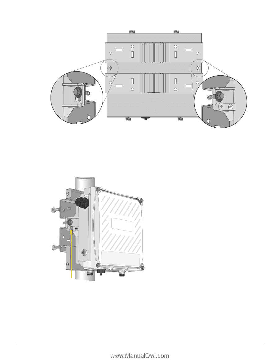
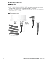
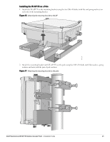
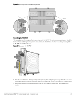
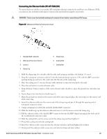
Figure 19 Attaching the AP to the Mounting Bracket Front Front Grounding the W-AP175 The grounding must be completed before powering up the W-AP175. The resistance of grounding wire should be less than 5 ohm and the grounding cable's cross-section area should be no less than 6 mm.The grounding hole is at the right side of the W-AP175. Figure 20 Grounding the W-AP175 AP175_04 1. Peel the cover of one end of the grounding cable (green or yellow and green grounding cable with 6 mm crosssection area) and place the bare grounding cable into the copper lug, and press firmly with the crimping pliers. 2. Fasten the copper lug to the grounding hole on the W-AP175 with the M4 x12 bolt and external-tooth washer. Dell PowerConnect W-AP175 Outdoor Access Point | Installation Guide 23
-
 1
1 -
2
-
3
-
4
-
5
-
6
-
7
-
8
-
9
-
10
-
11
-
12
-
13
-
14
-
15
-
16
-
17
-
 18
18 -
 19
19 -
 20
20 -
 21
21 -
 22
22 -
 23
23 -
 24
24 -
 25
25 -
 26
26 -
 27
27 -
 28
28 -
29
-
30
-
31
-
32
 |
 |