Dell PowerConnect W-AP175 Dell PowerConnect W-AP175P Installation Guide - Page 3
W-AP175 Hardware Overview, Antenna Interface
 |
View all Dell PowerConnect W-AP175 manuals
Add to My Manuals
Save this manual to your list of manuals |
Page 3 highlights
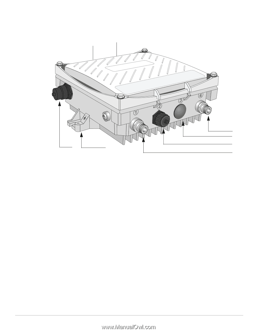
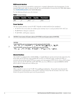
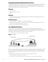
W-AP175 Hardware Overview The following section describes the hardware features of the W-AP175. Figure 1 W-AP175 Overview (W-AP175P shown) 5 6 4 3 7 8 2 1 1 Antenna Interface (Radio 1) 2 USB Console Interface 3 Reserved (W-AP175P) or Power Interface (W-AP175AC and W-AP175DC) 4 Antenna Interface (Radio 0) 5 Antenna Interface (Radio 0) 6 Antenna Interface (Radio 1) 7 Ethernet Interface (PoE) 8 Grounding Point Antenna Interface The W-AP175 requires the use of detachable outdoor-rated antennas. Select the correct antenna type to support the required frequency band (2.4 or 5 GHz) and the desired coverage pattern. The W-AP175 is equipped with four, female N-type antenna interfaces; two on the top of the AP and two on the bottom. The interfaces are grouped into diversity pairs, one pair is marked R0 (Radio 0) and the other pair marked as R1 (Radio 1). R0 supports the 5 GHz frequency band and R1 supports the 2.4 GHz radio band. Dell PowerConnect W-AP175 Outdoor Access Point | Installation Guide 3
-
 1
1 -
 2
2 -
 3
3 -
 4
4 -
 5
5 -
 6
6 -
 7
7 -
 8
8 -
 9
9 -
10
-
11
-
12
-
13
-
14
-
15
-
16
-
17
-
18
-
19
-
20
-
21
-
22
-
23
-
24
-
25
-
26
-
27
-
28
-
29
-
30
-
31
-
32
 |
 |