Dell PowerConnect W-AP175 Dell PowerConnect W-AP175P Installation Guide - Page 6
W-AP175AC/DC LED Status Indicators, Table 2
 |
View all Dell PowerConnect W-AP175 manuals
Add to My Manuals
Save this manual to your list of manuals |
Page 6 highlights
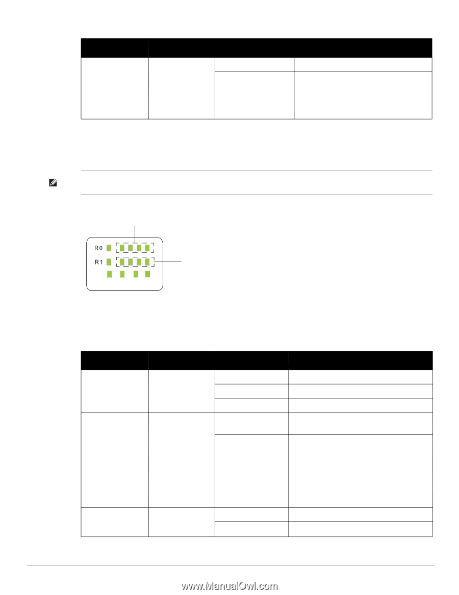
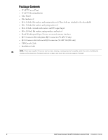
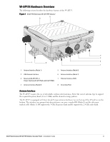
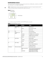
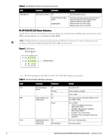
Table 2 W-AP175P LED Status Indicators (Continued) LED RSSI (Radio 1) Function Indicator RSSI Level for Radio 1 Off 4 Step Progressive Bars (Blue) 25/50/75/100% Status RSSI disabled/no signal Each bar represents a progressive increase in signal strength, with 4 bars representing maximum signal strength (100%). Minimum data rate: One lit LEDs Maximum data rate: Four lit LEDs W-AP175AC/DC LED Status Indicators The W-AP175 include visual indicators for power, link, heat and radio status. Additionally, each radio has a fourLED array that indicates received signal strength (RSSI). NOTE: The RSSI LED indicators represent varying degrees in the RSSI level. The absence of a signal is indicated by no LED response, and full signal strength is indicated when all four LEDs are active and lit. Figure 3 LED Layout RSSI for Radio 0 P/S POE HEAT ENT RSSI for Radio 1 Table 3 lists the meanings of the LEDs on the W-AP175AC/DC outdoor access points. Table 3 W-AP175AC/DC LED Status Indicators LED Function Indicator Status P/S AP Power/Ready Off No power to AP Status Blinking Device booting, not ready On Device ready POE Displays PSE power Off output status Non-powered device (0Ω
-
 1
1 -
 2
2 -
 3
3 -
 4
4 -
 5
5 -
 6
6 -
 7
7 -
 8
8 -
 9
9 -
 10
10 -
 11
11 -
 12
12 -
13
-
14
-
15
-
16
-
17
-
18
-
19
-
20
-
21
-
22
-
23
-
24
-
25
-
26
-
27
-
28
-
29
-
30
-
31
-
32
 |
 |