Dell PowerEdge C5125 Hardware Owner's Manual
Dell PowerEdge C5125 Manual
 |
View all Dell PowerEdge C5125 manuals
Add to My Manuals
Save this manual to your list of manuals |
Dell PowerEdge C5125 manual content summary:
- Dell PowerEdge C5125 | Hardware Owner's Manual - Page 1
Dell PowerEdge C5125 Hardware Owner's Manual Regulatory Model: B04S - Dell PowerEdge C5125 | Hardware Owner's Manual - Page 2
CAUTION indicates potential damage to hardware or loss of data if instructions are not followed. WARNING: A WARNING indicates a potential for property are trademarks of Advanced Micro Devices, Inc. Dell™, the DELL logo, and PowerEdge™ are trademarks of Dell Inc. Microsoft® and Windows® are either - Dell PowerEdge C5125 | Hardware Owner's Manual - Page 3
Contents 1 About the System 7 Front-Panel Features and Indicators 8 2 Using the System Setup Program 11 Setup Menu 11 BIOS Setup Options at Boot 12 Console Redirection 12 Configuring Special Keys 12 The Legend Bar 14 General Help 14 Access Level 15 Main Menu 16 Advanced Menu 19 Boot Menu - Dell PowerEdge C5125 | Hardware Owner's Manual - Page 4
3 Installing System Components 47 Recommended Tools 47 Inside the System 48 Sled Configuration 49 Removing a Sled 50 Installing a Sled 50 Removing Memory Modules 51 Installing a Memory Module 52 Removing 2.5" Hard-Drives 56 Installing 2.5" Hard-Drives 57 Removing 3.5" Hard-Drives 58 - Dell PowerEdge C5125 | Hardware Owner's Manual - Page 5
Board 77 Installing a PDB Board 79 Removing the RTC Battery 80 Installing the RTC Battery 81 4 Troubleshooting 83 Troubleshooting Sequence 83 5 Jumpers and Connectors 89 C5125 System Board Components 89 2.5" Hard-Drive Board Connectors 91 3.5" Hard-Drive Board Connectors 92 Backplane - Dell PowerEdge C5125 | Hardware Owner's Manual - Page 6
6 Getting Help 97 7 Index 99 6 - Dell PowerEdge C5125 | Hardware Owner's Manual - Page 7
configurations: • 12-sled, system board+ 3.5" hard-drive board+cables • 12-sled, system board + 2.5" hard-drive board+cables Server management for the C5125 sled is available through a dedicated NIC port at the front of the system. For more information, see "Front-Panel Features and Indicators" on - Dell PowerEdge C5125 | Hardware Owner's Manual - Page 8
ON/OFF button for sled 5 NIC LAN ports 10/100/1G NIC LAN connector 1 10/100/1G NIC LAN connector 2 Sled Population Rules NOTE: The Dell PowerEdge C5000 is a blade enclosure supporting a Dell PowerEdge sled system. The following sled Stock Keeping Unit (SKU) is available for the - Dell PowerEdge C5125 | Hardware Owner's Manual - Page 9
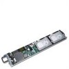
Sled LED Description Figure 1-2. Sled LEDs (Rotated Counter-clockwise 90°) 1 23 4 20 31 76 5 Item Feature Status 4, 2 LAN link LED OFF 3, 1 LAN activity LED OFF LAN link LED LAN activity LED Green OFF LAN link LED LAN activity LED Green OFF LAN link LED LAN activity LED Blinking - Dell PowerEdge C5125 | Hardware Owner's Manual - Page 10
10 About the System - Dell PowerEdge C5125 | Hardware Owner's Manual - Page 11
Using the System Setup Program Setup Menu The computer employs the latest AMI Core BIOS, which is stored in Flash memory. The Flash memory supports the Plug and Play specification, and contains a BIOS Setup program, the Power On Self Test (POST) routine, and the PCI auto-configuration utility. This - Dell PowerEdge C5125 | Hardware Owner's Manual - Page 12
allows a remote user to diagnose and fix problems on a server, which has not successfully booted serial console must be capable of supporting the functionality documented in the control keys in this character set. However, the PowerEdge C5000 software requires the use of function keys and - Dell PowerEdge C5125 | Hardware Owner's Manual - Page 13
For console redirection, an escape sequence starts with an escape character. This character can be entered in a variety of different ways depending on the requirements of your terminal emulation software. For example, 0x1b, ^[, and refer to the same escape character. The following table lists - Dell PowerEdge C5125 | Hardware Owner's Manual - Page 14
The Legend Bar The legend bar is at the side of the Setup screen. The keys in the legend bar allow you to navigate through the various setup menus. The following table lists the keys found in the legend bar with their corresponding alternates and functions. Legend Key F1 ? or + or Enter Page Down - Dell PowerEdge C5125 | Hardware Owner's Manual - Page 15
Access Level The Access Level property controls who has access to the control (supervisor or user). Table 2-1 summarizes the effect of Access Level on a control. Table 2-1. Access Level Summary Password(s) Password User Access Installed Entered Level Selected by Supervisor Access Level 0 Access - Dell PowerEdge C5125 | Hardware Owner's Manual - Page 16
System Overview AMIBIOS Version : 1.0.0 Build Date: 01/17/11 BIOS SETUP UTILITY Server Security Exit Product Information Name :PowerEdge C5125 Asset Tag :2234567890 Service Tag :1234567 ePPID :12345678901234567890123 Use [ENTER, [TAB] Or [SHIFT-TAB] to select a Field. Use to configure system - Dell PowerEdge C5125 | Hardware Owner's Manual - Page 17
date the BIOS was created. Product Information Option Description Name System product name. Asset Tag System asset tag number. Service Tag System service tag number. Electronic Piece Part Information from PPID label. Identification (ePPID) Processor Option Type Speed Counter Description - Dell PowerEdge C5125 | Hardware Owner's Manual - Page 18
Option System Date Control Group System Time System Date Description Scroll to this item to adjust the date. Use [ENTER], [TAB] or [SHIFT-TAB] to select a field. Use [+] or [-] to configure system date. User Access Level Access Level 2 Access Level 2 18 Using the System Setup Program - Dell PowerEdge C5125 | Hardware Owner's Manual - Page 19
Advanced Menu The Advanced screen provides an access point to configure several options. On this screen, the user selects the option that is to be configured. Configurations are performed on the selected screen, not directly on the Advanced screen. CAUTION: Making incorrect settings to items on - Dell PowerEdge C5125 | Hardware Owner's Manual - Page 20
Mode (SVM) F1 F10 ESC Select Screen Select Item Change Option General Help Save and Exit Exit *1: [800MHz] [2000MHz] NOTE: Default values shown NOTE: C1E support - The current BIOS disables the Enhanced C1 State - Dell PowerEdge C5125 | Hardware Owner's Manual - Page 21
Options: • Module Version : CPU module version. • AGESA Version : AMD Generic Encapsulated Software Architecture (AGESA) version number. • Physical Count : Number of physical CPUs. • Logical Count : Number of logical CPUs. • Revision : Processor revision • Cache L1: Information only. Displays the - Dell PowerEdge C5125 | Hardware Owner's Manual - Page 22
Screen Select Item Go to Sub Screen General Help Save and Exit Exit *1: [Native IDE] [AHCI] *2: [Enable] [Disabled]. Options include: • [Native IDE] - Supports up to four SATA ports. • [AHCI] -Supports all SATA ports using the Advanced Host Controller Interface. 22 Using the System Setup Program - Dell PowerEdge C5125 | Hardware Owner's Manual - Page 23
SATA Port0-3: [Not Detected][Hard Disk][ATAPI CDROM] While entering setup, BIOS auto detects the presence of SATA devices. This displays the status of auto detection of SATA devices. This item displays information only and is unavailable when AHCI Mode is enabled. Power Saving Features: Disable/ - Dell PowerEdge C5125 | Hardware Owner's Manual - Page 24
*2: [Disabled] [Enabled with PXE] [Enabled without PXE] *3: [Disabled] [Enabled with PXE] [Enabled without PXE] NIC1 - Intel 82576EB: [Disabled][Enabled with PXE][Enabled without PXE] NIC2 - Intel 82576EB: [Disabled][Enabled with PXE][Enabled without PXE] Control Group iSCSI Remote Boot NIC1 - - Dell PowerEdge C5125 | Hardware Owner's Manual - Page 25
Active State Power Management Configuration Scroll to this item and press to view the following screen: BIOS SETUP UTILITY Advanced Active State Power Management Configuration Onboard LAN ASPM NB-SB Link ASPM [Disabled] *1 [L1] *2 Active State Power Management (ASPM). F1 F10 ESC - Dell PowerEdge C5125 | Hardware Owner's Manual - Page 26
Module Version - 2.24.5-13.4 USB Devices Enabled: 1 Keyboard, 1 Mouse, 1 Hub, 1 Drive Enables support for legacy USB. AUTO option disables legacy support if no USB devices are connected. Legacy USB Support [Enabled] *1 • USB Mass Storage Device Configuration USB PORT 0 (Front 0) [Enabled] USB PORT - Dell PowerEdge C5125 | Hardware Owner's Manual - Page 27
Legacy USB Support: Control Group Legacy USB Support USB PORT 0(Front 0) USB PORT 1(Front 1) USB PORT 2(BMC) USB PORT 3(SSD) User Access Level Access Level 1 Access Level 1 Access Level 1 Access Level 1 Access Level 1 Using the System Setup Program 27 - Dell PowerEdge C5125 | Hardware Owner's Manual - Page 28
Boot Menu This page enables you to set POST boot parameters. Scroll to this item and press to view the following screen: Boot Settings BIOS SETUP UTILITY Boot • Boot Settings Configuration Configure Settings during System Boots. • Boot Device Priority • Network Device Enter F1 - Dell PowerEdge C5125 | Hardware Owner's Manual - Page 29
Boot Settings Configuration Select this item and press Enter to view the following submenu items: Boot Boot Settings Configuration Quick Boot Quiet Boot Wait For 'F1' If Error Force PXE First Force PXE First Boot Only Force USB First BIOS SETUP UTILITY [Enabled] [Enabled] [Disabled] [Enabled] *1 [ - Dell PowerEdge C5125 | Hardware Owner's Manual - Page 30
Force USB First: Enable/Disable USB to be the first boot device, the priority is higher than PXE. Control Group Quick Boot Quiet Boot Wait For 'F1' If Error Force PXE First Force PXE Boot Only Force USB First User Access Level Access Level 1 Access Level 1 Access Level 1 Access Level 1 Access - Dell PowerEdge C5125 | Hardware Owner's Manual - Page 31
Boot Device Priority Select this item and press to view the following submenu items: Boot Boot Device Priority 1st Boot Device BIOS SETUP UTILITY [Network:IBA GB Slo] Specifies the boot sequence from the available devices A device enclosed in parenthesis has been disabled in the - Dell PowerEdge C5125 | Hardware Owner's Manual - Page 32
Control Group 6th Boot Device 7th Boot Device 8th Boot Device 9th Boot Device 10th Boot Device 11th Boot Device 12th Boot Device User Access Level Access Level 1 Access Level 1 Access Level 1 Access Level 1 Access Level 1 Access Level 1 Access Level 1 32 Using the System Setup Program - Dell PowerEdge C5125 | Hardware Owner's Manual - Page 33
76-53] [Power On] [Immediate] *1 Input for Set LAN Configuration command. See IPMI 2.0 Spec, table 23-1 NOTE: Each question in this group may take considerable amount of time. Event Control Version: Information only. Displays the BMC support IPMI version. Using the System Setup Program 33 - Dell PowerEdge C5125 | Hardware Owner's Manual - Page 34
BMC Firmware Version: Information only. Displays the Firmware version of BMC. NIC1 Mac Address: [xx-xx-xx-xx-xx-xx] Information only. Displays the NIC1 MAC address. NIC2 Mac Address: [xx-xx-xx-xx-xx-xx] Information only. Displays the NIC2 MAC address. Set BMC LAN Configuration: Input for Set LAN - Dell PowerEdge C5125 | Hardware Owner's Manual - Page 35
BMC LAN Configuration The BMC LAN Configuration screen provides a way to configure BMC LAN setting. Scroll to this item and press to view the following screen: LAN Configuration Channel Number Channel Number Status: BIOS SETUP UTILITY Server [01] Status is OK Set BMC LAN port to dedicated - Dell PowerEdge C5125 | Hardware Owner's Manual - Page 36
IRQ [3F8h, 4] Serial Port Mode [115200 8,n,1]*2 Flow Control [None] *3 Redirection After BIOS POST [Always]*5 Terminal Type [ANSI]*4 VT-UTF8 Combo Key Support [Enabled] Select Remote Access type. F1 F10 ESC Select Screen Select Item Change Option General Help Save and Exit Exit - Dell PowerEdge C5125 | Hardware Owner's Manual - Page 37
active. (Some OSs may not work if set to Always) Terminal Type: [ANSI][VT100][VT-UTF8] Select the target terminal type. VT-UTF8 Combo Key Support: [Disabled][Enabled]: Enable VT-UTF8 Combination Key Support for AN-SI/VT100 terminals Using the System Setup Program 37 - Dell PowerEdge C5125 | Hardware Owner's Manual - Page 38
View BMC Event Log Select View BMC Event Log to view the following submenu: BIOS SETUP UTILITY Server Total Number of Entries 2 SEL Entry Number [1] SEL Record ID: 0001 SEL Record Type: 02 (System Event) Event Timestamp: Unspecified Generator ID: 0001 Event Message Format Ver: 04 ( - Dell PowerEdge C5125 | Hardware Owner's Manual - Page 39
Security Menu The Security screen provides fields to enable and set the user and administrative password and to lockout the front panel buttons so they cannot be used. Scroll to this item and press to view the following screen: Security Settings Supervisor Password User Password BIOS SETUP - Dell PowerEdge C5125 | Hardware Owner's Manual - Page 40
Select this option and press to access the sub menu, a dialog box appears which lets you enter a password. You can enter no more than six letters or numbers. Press Enter after you have typed in the password. A second dialog box asks you to retype the password for confirmation. Press Enter - Dell PowerEdge C5125 | Hardware Owner's Manual - Page 41
Save Changes and Exit: Highlight this item and press Enter to save any changes that you have made in the Setup utility and exit the Setup utility. When the Save Changes and Exit dialog box appears, press to save the changes and exit, or press to return to the setup main menu. Discard Changes - Dell PowerEdge C5125 | Hardware Owner's Manual - Page 42
Loading BIOS Defaults Different mechanisms exist for resetting the system configuration to the default values. When a request to reset the system configuration is detected, the BIOS loads the default system configuration values during the next POST. The request to reset the system to the defaults - Dell PowerEdge C5125 | Hardware Owner's Manual - Page 43
POST Error Messages and Handling: Code 0000 0003 0004 0005 000B 000C 000E 000F 0012 0040 0041 0042 0044 0045 0046 0047 0048 0049 004A 004B 005E 005D 0060 0061 0062 0063 0080 0081 Error Message Timer Error CMOS Battery Low CMOS Settings Wrong CMOS Checksum Bad CMOS memory size Wrong RAM R/W test - Dell PowerEdge C5125 | Hardware Owner's Manual - Page 44
0082 Secondary Master Drive - ATAPI Incompatible Pause 0083 Secondary Slave Drive - ATAPI Incompatible Pause 0160 The processors installed in your system are not able to match their frequencies. Pause 0162 The processors installed in your system do not have the Halt same cache size. - Dell PowerEdge C5125 | Hardware Owner's Manual - Page 45
!!! 8102 Error! USB device failed to initialize!!! WARNING 8103 Warning! Unsupported UBS device found and disabled!!! WARNING 8104 Warning! Port 60h/64h emulation is not supported by this WARNING USB Host Controller!!! 8105 Warning! EHCI controller disabled. It requires 64-bit data Pause - Dell PowerEdge C5125 | Hardware Owner's Manual - Page 46
46 Using the System Setup Program - Dell PowerEdge C5125 | Hardware Owner's Manual - Page 47
3 Installing System Components Recommended Tools • Phillips screwdriver • Flat-tipped screwdriver • Set of jewellers screwdrivers • A grounding strap • An anti-static pad Installing System Components 47 - Dell PowerEdge C5125 | Hardware Owner's Manual - Page 48
should only perform troubleshooting and simple repairs as authorized in your product documentation, or as directed by the online or telephone service and support team. Damage due to servicing that is not authorized is not covered by warranty. Read and follow the safety instructions that came with - Dell PowerEdge C5125 | Hardware Owner's Manual - Page 49
Sled Configuration Figure 3-2 shows the 12-sled configuration with the corresponding bay numbering. Figure 3-2. PowerEdge C5000 12-Sled SKU 2 1 2 3 4 5 6 7 8 9 10 11 12 Installing System Components 49 - Dell PowerEdge C5125 | Hardware Owner's Manual - Page 50
should only perform troubleshooting and simple repairs as authorized in your product documentation, or as directed by the online or telephone service and support team. Damage due to servicing that is not authorized is not covered by warranty. Read and follow the safety instructions that came with - Dell PowerEdge C5125 | Hardware Owner's Manual - Page 51
should only perform troubleshooting and simple repairs as authorized in your product documentation, or as directed by the online or telephone service and support team. Damage due to servicing that is not authorized is not covered by warranty. Read and follow the safety instructions that came with - Dell PowerEdge C5125 | Hardware Owner's Manual - Page 52
should only perform troubleshooting and simple repairs as authorized in your product documentation, or as directed by the online or telephone service and support team. Damage due to servicing that is not authorized is not covered by warranty. Read and follow the safety instructions that came with - Dell PowerEdge C5125 | Hardware Owner's Manual - Page 53
DIMM Configuration The following DIMM configurations are supported by the C5125 system. Figure 3-5. DIMM slot configuration DIMM_A0 DIMM_B0 B1 A1 B0 A0 DIMM_A1 DIMM_B1 DIMM Population Rules For one DIMM, only install in DIMM A1/B1. - Dell PowerEdge C5125 | Hardware Owner's Manual - Page 54
DDR Rate 1.5V 800 800 800 1066 1066 1066 1066 1066 1066 1066 1066 1066 1066 1066 1066 1333 1333 1333 1333 1333 1333 1333 1333 1333 1333 1333 1333 DDR Rate 1.35V 800 800 800 1066 1066 1066 1066 1066 1066 1066 1066 1066 1066 1066 1066 N/A N/A N/A N/A N/A N/A N/A N/A N/A N/A N/A N/A DIMM0 DR-x8 SR-x8 - Dell PowerEdge C5125 | Hardware Owner's Manual - Page 55
Supported Memory Supported Memory Config- Memory Type/Size uration CPU DIMMs Type Memory Speed (MHz) Rank Type Component Total (x8, x4) Density Size DIMM Slot A0 B0 A1 - Dell PowerEdge C5125 | Hardware Owner's Manual - Page 56
should only perform troubleshooting and simple repairs as authorized in your product documentation, or as directed by the online or telephone service and support team. Damage due to servicing that is not authorized is not covered by warranty. Read and follow the safety instructions that came with - Dell PowerEdge C5125 | Hardware Owner's Manual - Page 57
should only perform troubleshooting and simple repairs as authorized in your product documentation, or as directed by the online or telephone service and support team. Damage due to servicing that is not authorized is not covered by warranty. Read and follow the safety instructions that came with - Dell PowerEdge C5125 | Hardware Owner's Manual - Page 58
should only perform troubleshooting and simple repairs as authorized in your product documentation, or as directed by the online or telephone service and support team. Damage due to servicing that is not authorized is not covered by warranty. Read and follow the safety instructions that came with - Dell PowerEdge C5125 | Hardware Owner's Manual - Page 59
Figure 3-10. Removing and Installing the 3.5" Hard-Drives From the Sled 3.5" HDD HDD0 3.5" HDD HDD1 HDD0 HDD1 SATA0 SATA1 HDD0 HDD1 1 2 1 3 1 4 1 cable clip 3 hard-drive 1 power connector 2 hard-drive 0 power connector 4 hard-drive SATA connectors 5 Disconnect the hard-drive cables - Dell PowerEdge C5125 | Hardware Owner's Manual - Page 60
should only perform troubleshooting and simple repairs as authorized in your product documentation, or as directed by the online or telephone service and support team. Damage due to servicing that is not authorized is not covered by warranty. Read and follow the safety instructions that came with - Dell PowerEdge C5125 | Hardware Owner's Manual - Page 61
should only perform troubleshooting and simple repairs as authorized in your product documentation, or as directed by the online or telephone service and support team. Damage due to servicing that is not authorized is not covered by warranty. Read and follow the safety instructions that came with - Dell PowerEdge C5125 | Hardware Owner's Manual - Page 62
should only perform troubleshooting and simple repairs as authorized in your product documentation, or as directed by the online or telephone service and support team. Damage due to servicing that is not authorized is not covered by warranty. Read and follow the safety instructions that came with - Dell PowerEdge C5125 | Hardware Owner's Manual - Page 63
should only perform troubleshooting and simple repairs as authorized in your product documentation, or as directed by the online or telephone service and support team. Damage due to servicing that is not authorized is not covered by warranty. Read and follow the safety instructions that came with - Dell PowerEdge C5125 | Hardware Owner's Manual - Page 64
should only perform troubleshooting and simple repairs as authorized in your product documentation, or as directed by the online or telephone service and support team. Damage due to servicing that is not authorized is not covered by warranty. Read and follow the safety instructions that came with - Dell PowerEdge C5125 | Hardware Owner's Manual - Page 65
should only perform troubleshooting and simple repairs as authorized in your product documentation, or as directed by the online or telephone service and support team. Damage due to servicing that is not authorized is not covered by warranty. Read and follow the safety instructions that came with - Dell PowerEdge C5125 | Hardware Owner's Manual - Page 66
should only perform troubleshooting and simple repairs as authorized in your product documentation, or as directed by the online or telephone service and support team. Damage due to servicing that is not authorized is not covered by warranty. Read and follow the safety instructions that came with - Dell PowerEdge C5125 | Hardware Owner's Manual - Page 67
should only perform troubleshooting and simple repairs as authorized in your product documentation, or as directed by the online or telephone service and support team. Damage due to servicing that is not authorized is not covered by warranty. Read and follow the safety instructions that came with - Dell PowerEdge C5125 | Hardware Owner's Manual - Page 68
should only perform troubleshooting and simple repairs as authorized in your product documentation, or as directed by the online or telephone service and support team. Damage due to servicing that is not authorized is not covered by warranty. Read and follow the safety instructions that came with - Dell PowerEdge C5125 | Hardware Owner's Manual - Page 69
should only perform troubleshooting and simple repairs as authorized in your product documentation, or as directed by the online or telephone service and support team. Damage due to servicing that is not authorized is not covered by warranty. Read and follow the safety instructions that came with - Dell PowerEdge C5125 | Hardware Owner's Manual - Page 70
should only perform troubleshooting and simple repairs as authorized in your product documentation, or as directed by the online or telephone service and support team. Damage due to servicing that is not authorized is not covered by warranty. Read and follow the safety instructions that came with - Dell PowerEdge C5125 | Hardware Owner's Manual - Page 71
should only perform troubleshooting and simple repairs as authorized in your product documentation, or as directed by the online or telephone service and support team. Damage due to servicing that is not authorized is not covered by warranty. Read and follow the safety instructions that came with - Dell PowerEdge C5125 | Hardware Owner's Manual - Page 72
should only perform troubleshooting and simple repairs as authorized in your product documentation, or as directed by the online or telephone service and support team. Damage due to servicing that is not authorized is not covered by warranty. Read and follow the safety instructions that came with - Dell PowerEdge C5125 | Hardware Owner's Manual - Page 73
4 Disconnect all system and PSU fan cables from the backplane and remove the system fan cables from the cable clips. See Figure 3-22. Figure 3-22. Disconnecting and Connecting the Fan Cables 1 4 2 5 3 67 8 1 fan and connector 1 3 fan and connector 3 5 fan and connector 5 7 fan and connector 7 2 - Dell PowerEdge C5125 | Hardware Owner's Manual - Page 74
should only perform troubleshooting and simple repairs as authorized in your product documentation, or as directed by the online or telephone service and support team. Damage due to servicing that is not authorized is not covered by warranty. Read and follow the safety instructions that came with - Dell PowerEdge C5125 | Hardware Owner's Manual - Page 75
Figure 3-23. Removing and Installing the Backplane Cables 1 2 3 4 5 6 1 LAN connector 3 PMBus 2 connector 5 PSU 1 connector 2 sideband connector 4 PMBus 1connector 6 PSU 2 connector 7 Remove the two screws behind the power cord bracket attaching the grounding cables to the chassis. See Figure 3- - Dell PowerEdge C5125 | Hardware Owner's Manual - Page 76
8 Remove the two screws from the sides of the power cord bracket. See Figure 3-25. 9 Remove the power cord bracket. See Figure 3-25. Figure 3-25. Removing and Installing the Power Cord Bracket 10 Remove the thirteen screws from the backplane. See Figure 3-26. 11 Remove the backplane from the chassis - Dell PowerEdge C5125 | Hardware Owner's Manual - Page 77
should only perform troubleshooting and simple repairs as authorized in your product documentation, or as directed by the online or telephone service and support team. Damage due to servicing that is not authorized is not covered by warranty. Read and follow the safety instructions that came with - Dell PowerEdge C5125 | Hardware Owner's Manual - Page 78
4 Guide the PSU1 and the PSU2 power cables through the opening in the middle wall on the chassis. See Figure 3-27. 5 Remove the three screws from - Dell PowerEdge C5125 | Hardware Owner's Manual - Page 79
troubleshooting and simple repairs as authorized in your product documentation, or as directed by the online or telephone service and support team. Damage due to servicing that is not authorized is not covered by warranty. Read and follow the safety instructions Figure 3-27. 7 Guide the PSU1 and the - Dell PowerEdge C5125 | Hardware Owner's Manual - Page 80
should only perform troubleshooting and simple repairs as authorized in your product documentation, or as directed by the online or telephone service and support team. Damage due to servicing that is not authorized is not covered by warranty. Read and follow the safety instructions that came with - Dell PowerEdge C5125 | Hardware Owner's Manual - Page 81
should only perform troubleshooting and simple repairs as authorized in your product documentation, or as directed by the online or telephone service and support team. Damage due to servicing that is not authorized is not covered by warranty. Read and follow the safety instructions that came with - Dell PowerEdge C5125 | Hardware Owner's Manual - Page 82
82 Installing System Components - Dell PowerEdge C5125 | Hardware Owner's Manual - Page 83
Does Not Boot After Configuration Changes Hardware Changes Software Changes BIOS Changes Viewing System Event Logs For Investigation Installation Problems Troubleshooting External Connections System Does Not Boot After Initial Installation Power Connector Not Plugged In If the power supply cable - Dell PowerEdge C5125 | Hardware Owner's Manual - Page 84
indicator LEDs showing status. Refer to the monitor's documentation to confirm operation. If the problem still persists, test or replace the monitor on a different AC outlet/different system. Power cables and connectors are firmly connected to the power supply and the AC outlet. 84 Troubleshooting - Dell PowerEdge C5125 | Hardware Owner's Manual - Page 85
one at a time to isolate which one is causing the problem. If the problem occurs even after removing the non-essential components, the problem has to be with the server board, power supply, memory, new components, verify that the component installed is compatible with the server. Troubleshooting 85 - Dell PowerEdge C5125 | Hardware Owner's Manual - Page 86
BMC is working, try to gather system event log (SEL) information for investigation (see "View BMC Event Log" on page 38 for more information). 86 Troubleshooting - Dell PowerEdge C5125 | Hardware Owner's Manual - Page 87
AC power. Check the AC power cord to make sure that it is securely connected. Troubleshooting External Connections Loose or improperly connected cables are the most likely source of problems for the system, monitor, and other peripherals (such as a printer, keyboard, mouse, or other external - Dell PowerEdge C5125 | Hardware Owner's Manual - Page 88
88 Troubleshooting - Dell PowerEdge C5125 | Hardware Owner's Manual - Page 89
Jumpers and Connectors C5125 System Board Components Figure 5-1 displays the system components on the system board. Figure 5-1. System Board Diagram Front 17 1 5 2 16 3 15 4 14 5 6 13 7 12 8 9 Rear 11 10 Jumpers and Connectors 89 - Dell PowerEdge C5125 | Hardware Owner's Manual - Page 90
1 VGA/USB port 3 processor socket 5 BMC COM port 7 JP11 COM port jumper 9 COM port 11 SATA connectors 13 hard-drive active LED connector 15 CMOS clear jumper 17 power button connector 2 NIC1 and NIC2 4 BMC disable jumper 6 IPMB connector 8 JP12 COM port jumper 10 SSD header 12 PCIe (Sideband) x1 14 - Dell PowerEdge C5125 | Hardware Owner's Manual - Page 91
2.5" Hard-Drive Board Connectors Figure 5-2 shows the connectors on the 2.5" hard-drive board. Figure 5-2. 2.5" Hard-Drive Board 11 10 9 8 7 1 2 3 1 backplane connector 3 hard-drive 2 connector 5 hard-drive 0 connector 7 hard-drive LED connector 9 hard-drive 1 SATA connector 11 hard-drive 0 - Dell PowerEdge C5125 | Hardware Owner's Manual - Page 92
3.5" Hard-Drive Board Connectors Figure 5-3 shows connectors on the 3.5" hard-drive board. Figure 5-3. 3.5" Hard-Drive Board 5 1 2 3 4 1 backplane connector 3 hard-drive 1 power connector 5 hard-drive LED connector Backplane Connectors 2 hard-drive 0 power connector 4 system board gold finger - Dell PowerEdge C5125 | Hardware Owner's Manual - Page 93
1 sled 1 connector 3 sled 3 connector 5 sled 5 connector 7 sled 7 connector 9 sled 9 connector 11 sled 11 connector 2 sled 2 connector 4 sled 4 connector 6 sled 6 connector 8 sled 8 connector 10 sled 10 connector 12 sled 12 connector 12-Sled Backplane Rear Connectors Figure 5-5 shows the - Dell PowerEdge C5125 | Hardware Owner's Manual - Page 94
Table 5-2. 12-Sled Backplane Jumper Positions MD2 MD1 Mode 0 1 Normal 1 1 JTAG 1 0 Boot Power Distribution Board Connectors Figure 5-6 shows the connectors on the PDB. Figure 5-6. PDB Connectors 1 2 1 PSU connector 2 PMBus connector PDB Power and PMBus Connectors This section - Dell PowerEdge C5125 | Hardware Owner's Manual - Page 95
Table 5-3. PDB Power and SMBus Connector Pin Out Pin Signal 5 +12V 7 +12V 9 +12V 11 PS_PRESENT_0 13 GND 15 GND 17 GND 19 GND 21 GND 23 P12V_STB Pin Signal 6 +12V 8 +12V 10 CSHARE 12 +12V 14 GND 16 GND 18 GND 20 GND 22 P12V_STB 24 GND Pin Signal Pin - Dell PowerEdge C5125 | Hardware Owner's Manual - Page 96
96 Jumpers and Connectors - Dell PowerEdge C5125 | Hardware Owner's Manual - Page 97
provides several online and telephone-based support and service options. Availability varies by country and product, and some services may not be available in your area. To contact Dell for sales, technical support, or customer service issues: 1 Visit support.dell.com. 2 Click your country/region at - Dell PowerEdge C5125 | Hardware Owner's Manual - Page 98
98 Getting Help - Dell PowerEdge C5125 | Hardware Owner's Manual - Page 99
7 access level 15 C connector system board 89 contacting dell 97 D Dell contacting 97 DIMM configuration 53 population rules 53 I installing 69 RTC Battery 81 sled 50 system board 67 IRQ assignment conflicts 45 M memory supported 55 menu advanced 19 boot 28 exit 40 main 16 security 39 server 33 R - Dell PowerEdge C5125 | Hardware Owner's Manual - Page 100
sled configuration 49 front features 8 LED description 9 population rules 8 special keys configuring 12 system configurations 7 inside 48 setup program 11 T tools recommended 47 troubleshooting sequence 83 100
-
 1
1 -
 2
2 -
 3
3 -
 4
4 -
 5
5 -
 6
6 -
 7
7 -
8
-
9
-
10
-
11
-
12
-
13
-
14
-
15
-
16
-
17
-
18
-
19
-
20
-
21
-
22
-
23
-
24
-
25
-
26
-
27
-
28
-
29
-
30
-
31
-
32
-
33
-
34
-
35
-
36
-
37
-
38
-
39
-
40
-
41
-
42
-
43
-
44
-
45
-
46
-
47
-
48
-
49
-
50
-
51
-
52
-
53
-
54
-
55
-
56
-
57
-
58
-
59
-
60
-
61
-
62
-
63
-
64
-
65
-
66
-
67
-
68
-
69
-
70
-
71
-
72
-
73
-
74
-
75
-
76
-
77
-
78
-
79
-
80
-
81
-
82
-
83
-
84
-
85
-
86
-
87
-
88
-
89
-
90
-
91
-
92
-
93
-
94
-
95
-
96
-
97
-
98
-
99
-
100
 |
 |

Dell PowerEdge C5125
Hardware Owner’s
Manual
Regulatory Model: B04S