Dell PowerEdge PDU Managed LED Cabling PowerEdge R415
Dell PowerEdge PDU Managed LED Manual
 |
View all Dell PowerEdge PDU Managed LED manuals
Add to My Manuals
Save this manual to your list of manuals |
Dell PowerEdge PDU Managed LED manual content summary:
- Dell PowerEdge PDU Managed LED | Cabling PowerEdge R415 - Page 1
Cable Routing Procedures for Dell™ PowerEdge™ R415 Systems A Dell™ Technical White Paper By Greg Henderson, Chris Kitten and Jose L. Flores Dell™ │ Datacenter Infrastructure Engineering March 2011 - Dell PowerEdge PDU Managed LED | Cabling PowerEdge R415 - Page 2
Cable Routing Procedures for Dell™ PowerEdge™ R415 Systems THIS WHITE PAPER IS FOR INFORMATIONAL PURPOSES ONLY, AND MAY CONTAIN TYPOGRAPHICAL ERRORS AND TECHNICAL INACCURACIES. THE CONTENT IS PROVIDED AS IS, WITHOUT EXPRESS OR IMPLIED WARRANTIES OF ANY KIND. © 2011 Dell Inc. All rights reserved. - Dell PowerEdge PDU Managed LED | Cabling PowerEdge R415 - Page 3
Cables Through the Strain Reliefs 3 1.4 Routing the Cables Through the CMA...3 1.5 Left-Side Mounting Instructions...4 1.6 Right-Side Mounting Instructions ...6 Section 2: Cabling a Dell™ PowerEdge™ R415 System Without a CMA 7 2.1 Routing the Cables ...7 2.2 Removing the CMA Brackets for Shallow - Dell PowerEdge PDU Managed LED | Cabling PowerEdge R415 - Page 4
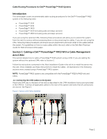
. Section 1: Cabling a Dell™ PowerEdge™ R415 With a Cable Management Arm (CMA) This section details how to cable a PowerEdge™ R415 system using a CMA. If you are cabling the system without the optional CMA, refer to Section 2. Follow the instructions contained in the Rack Installation Guide in the - Dell PowerEdge PDU Managed LED | Cabling PowerEdge R415 - Page 5
Cable Routing Procedures for Dell™ PowerEdge™ R415 Systems 1.2 Installing the Inner CMA Attachment Bracket As described in the Rack Installation Instructions, locate and attach the appropriate inner CMA attachment bracket based on which side you wish to mount the CMA. Use the bracket marked "A" for - Dell PowerEdge PDU Managed LED | Cabling PowerEdge R415 - Page 6
Cable Routing Procedures for Dell™ PowerEdge™ R415 Systems NOTE: For guidelines on how to route cables within the rack, refer to the Dell Best Practices Guide for Rack Enclosures white paper. 1.5 Left-Side Mounting Instructions 1. Install the CMA on the rear left side of the rails by attaching both - Dell PowerEdge PDU Managed LED | Cabling PowerEdge R415 - Page 7
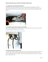
Cable Routing Procedures for Dell™ PowerEdge™ R415 Systems Figure 5: Attaching the KVM Dongle to the CMA Basket KVM Dongle Use the hook and loop straps on the CMA basket to secure - Dell PowerEdge PDU Managed LED | Cabling PowerEdge R415 - Page 8
Cable Routing Procedures for Dell™ PowerEdge™ R415 Systems Figure 6: Left-Side Mounted CMA Installation (Preferred) 1.6 Right-Side Mounting Instructions Install the CMA on the rear right side of the rails by attaching both CMA housings to the attachment brackets on the rails. Follow steps 2-6 - Dell PowerEdge PDU Managed LED | Cabling PowerEdge R415 - Page 9
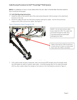
Dell™ PowerEdge™ R415 Systems Section 2: Cabling a Dell™ PowerEdge™ R415 System Without a CMA NOTE: The CMA on Dell™ PowerEdge brackets as described in the Rack Installation Instructions. See Figure 8 for an example system into a shallow rack (less than 1 meter deep) and you will not be installing a - Dell PowerEdge PDU Managed LED | Cabling PowerEdge R415 - Page 10
Dell™ PowerEdge™ R415 Systems Figure 9: Removing the CMA Brackets for Shallow Racks Section 3: Replacing a Power Supply on a PowerEdge™ R415 System With a CMA 1. Remove the tray from underneath the CMA as described in the CMA Installation Instructions Figure 10. b. While supporting the CMA with one - Dell PowerEdge PDU Managed LED | Cabling PowerEdge R415 - Page 11
Dell™ PowerEdge™ R415 Systems Figure 10: Disconnecting the Inner CMA Attachment Bracket Figure 11: Replacing the Outer Power Supply Disconnected inner CMA bracket Section 4: Cabling a PowerEdge in the Rack Installation Instructions. 3. Connect all applicable cables to the rear of the system and - Dell PowerEdge PDU Managed LED | Cabling PowerEdge R415 - Page 12
Cable Routing Procedures for Dell™ PowerEdge™ R415 Systems 4. Using the hook and loop straps, bundle the cables and secure them to either the left rail or right rail as described in the Rack Installation Instructions. See Figure 12 for an example of data cables that are secured to the left rail and
-
 1
1 -
 2
2 -
 3
3 -
 4
4 -
 5
5 -
 6
6 -
 7
7 -
8
-
9
-
10
-
11
-
12
 |
 |

Cable Routing Procedures for
Dell™ PowerEdge™ R415 Systems
A Dell
™
Technical White Paper
By Greg Henderson, Chris Kitten and Jose L. Flores
Dell
™
│
Datacenter Infrastructure Engineering
March 2011