Dell PowerSwitch S5000 S5000 Installation Guide 9.7.0.0 December 2017
Dell PowerSwitch S5000 Manual
 |
View all Dell PowerSwitch S5000 manuals
Add to My Manuals
Save this manual to your list of manuals |
Dell PowerSwitch S5000 manual content summary:
- Dell PowerSwitch S5000 | S5000 Installation Guide 9.7.0.0 December 2017 - Page 1
S5000 Installation Guide 9.7.0.0 December 2017 - Dell PowerSwitch S5000 | S5000 Installation Guide 9.7.0.0 December 2017 - Page 2
use of your computer. CAUTION: A CAUTION indicates either potential damage to hardware or loss of data and tells you how to avoid the problem. WARNING: A WARNING indicates a potential for property damage, personal injury, or death. Copyright © 2014 Dell Inc. All rights reserved. This product is - Dell PowerSwitch S5000 | S5000 Installation Guide 9.7.0.0 December 2017 - Page 3
Contents 1 About this Guide...5 Related Publications...5 2 Introduction...6 Product Description...6 3 Unpacking the Switch...7 Important Points Before You Continue...7 Hardware Installation Overview...8 4 Hardware Overview...9 I/O Panel...9 Utility Panel...10 Power Supplies...10 - Dell PowerSwitch S5000 | S5000 Installation Guide 9.7.0.0 December 2017 - Page 4
Class A Equipment...41 Korean Certification of Compliance...41 Safety Standards and Compliance Agency Certifications 42 Electromagnetic Compatibility (EMC)...42 Product Recycling and Disposal...42 9 Technical Support...44 Accessing Dell Networking Technical - Dell PowerSwitch S5000 | S5000 Installation Guide 9.7.0.0 December 2017 - Page 5
Guide This guide OS Configuration Guide for the Command Line Reference Guide for the guide before you install and power up this equipment. This equipment contains two power cords. Disconnect both power cords before servicing Guide for the S5000 Switch • Dell Networking OS Command Line Reference Guide - Dell PowerSwitch S5000 | S5000 Installation Guide 9.7.0.0 December 2017 - Page 6
OS Configuration Guide for the S5000 Switch, which is available on the Dell Support website at www.dell.com/support This document form factor. The S5000 supports Data Center Bridging (ETS/PFC/DCBX), FCoE Transit (FIP Snooping), NPIV Proxy Gateway (NPG), FC Fabric services (zoning, name server, - Dell PowerSwitch S5000 | S5000 Installation Guide 9.7.0.0 December 2017 - Page 7
damaged, contact your Dell Networking representative or reseller for instructions. WARNING: Electrostatic discharge (ESD) damage can occur (country/region specific) • Getting Started Guide • Safety and Regulatory Information • Warranty and Support Information • Software License Agreement 1. Place - Dell PowerSwitch S5000 | S5000 Installation Guide 9.7.0.0 December 2017 - Page 8
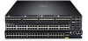
Figure 1. S5000 I/O and Utility Panels 1. I/O panel 3. Four 40GbE QSFP+ ports (each port ALSO supports 4 × 10GbE mode) 2. Utility panel Hardware Installation Overview To install the S5000, follow these steps: 1. Attach the mounting brackets. 2. Install the S5000 chassis into a 4-post rack - Dell PowerSwitch S5000 | S5000 Installation Guide 9.7.0.0 December 2017 - Page 9
RS-232 console port with YOST RJ-45 pinout and a dedicated Ethernet service port for out-ofband (OOB) management functions. I/O Panel All fixed (supports Ethernet and Unified Port modules) 2. Slot 1 (supports only Ethernet modules) 3. Slot 2 (supports only Ethernet modules) 4. Slot 3 (supports - Dell PowerSwitch S5000 | S5000 Installation Guide 9.7.0.0 December 2017 - Page 10
0) 3. Slot 2 (for Fan Module 1) 5. Grab Handles 2. Slot 1 (for Fan Module 0) 4. Slot 3 (for PSU 1) Power Supplies The S5000 supports two hot-swappable PSUs. The S5000 has SKUs that support the following configurations: • AC PSU with fan airflow from I/O to Utility • AC-R PSU with fan airflow from - Dell PowerSwitch S5000 | S5000 Installation Guide 9.7.0.0 December 2017 - Page 11
panel. You can also use the 40GbE ports in 4 × 10GbE mode. The S5000 supports the following possible modules: • 12-Port Ethernet Module (100MbE/1GbE/10GbE speeds, RJ-45 the Dell Networking OS Command Line Reference Guide and Dell Networking OS Configuration Guide for the S5000 Switch. As shown in - Dell PowerSwitch S5000 | S5000 Installation Guide 9.7.0.0 December 2017 - Page 12
alarm System status LED • Off • Green solid • Green blinking • Amber solid • No power • Normal operation • System is booting • System in card problem state Master LED • Green solid • Green blinking • Switch in Stacking Master mode OR Switch in Standalone mode • Switch in Stacking Standby mode - Dell PowerSwitch S5000 | S5000 Installation Guide 9.7.0.0 December 2017 - Page 13
beacon LED • Off • Blue • No activity • Module beacon/locator Module status LED • Off • Green solid • Yellow • Module is not powered up • Module is powered up • Problem detected with module 13 - Dell PowerSwitch S5000 | S5000 Installation Guide 9.7.0.0 December 2017 - Page 14
, interface enabled • 1G/100M link activity • Port beacon/locator • Module is not powered up • Module is powered up and functioning normal • Problem detected with module • No activity • Module beacon/locator Description • No activity • Port beacon/locator • Fibre Channel mode enabled • No link or - Dell PowerSwitch S5000 | S5000 Installation Guide 9.7.0.0 December 2017 - Page 15
Table 5. 40GbE Port/Module LEDs Label Port link/activity LED LED Color/Display • Off • Green solid • Green blinking Description • No link or interface disabled • Link present and interface enabled • Port has activity 15 - Dell PowerSwitch S5000 | S5000 Installation Guide 9.7.0.0 December 2017 - Page 16
Components Site Selection Dell Networking equipment is intended for installation in restricted access areas. A restricted access area can only be accessed by service personnel by using a special tool, lock, key or other means of security and access is controlled by the authority responsible for the - Dell PowerSwitch S5000 | S5000 Installation Guide 9.7.0.0 December 2017 - Page 17
Storing Components If you do not install your S5000 and components immediately, Dell Networking recommends properly storing the system and all optional components until you are ready to install them. WARNING: ESD damage can occur when components are mishandled. Always wear an ESD-preventive wrist or - Dell PowerSwitch S5000 | S5000 Installation Guide 9.7.0.0 December 2017 - Page 18
Installation This document contains the following sections: • Before You Begin • Install the S5000 Chassis in a Rack or Cabinet • Attaching the Mounting Brackets • Rack Mounting Safety Considerations • Installing the S5000 Chassis into a 4-post rack or cabinet • Rack Grounding • Important Points to - Dell PowerSwitch S5000 | S5000 Installation Guide 9.7.0.0 December 2017 - Page 19
• Cabling is away from sources of electrical noise, such as radios, power lines, and fluorescent lighting. Make sure that the cabling is safely away from other devices that might damage the cables. If needed, allow one rack unit (RU) space between devices to provide room for cabling. • Airflow - Dell PowerSwitch S5000 | S5000 Installation Guide 9.7.0.0 December 2017 - Page 20
. • Do not mount the equipment with the Utility panel facing in the downward position. WARNING: These instructions are a condensed reference. Read the safety instructions in your Safety, Environmental, and Regulatory information booklet before you begin. NOTE: The illustrations in this document - Dell PowerSwitch S5000 | S5000 Installation Guide 9.7.0.0 December 2017 - Page 21
prepare your equipment rack, ensure that the rack is earth ground. You must ground the equipment rack to the same ground point the power service uses in your area. The ground path must be permanent. Important Points to Remember for Installing an Ethernet Module • Installing and swapping of Ethernet - Dell PowerSwitch S5000 | S5000 Installation Guide 9.7.0.0 December 2017 - Page 22
. Instead, you must power down the switch before removing and replacing an Ethernet module. A red color release latch indicates that the Ethernet module supports hot swapping during switch operations. Figure 11. Part name and Port number on the Ethernet Module Handle 1 Part Name . 2 Port Number - Dell PowerSwitch S5000 | S5000 Installation Guide 9.7.0.0 December 2017 - Page 23
is powered up, the system does not recognize the module. Online insertion of modules can result in a catastrophic failure. • The S5000 does not support the hot swapping of a Unified Port pluggable module during switch operations. Instead, you must power down the switch before removing and replacing - Dell PowerSwitch S5000 | S5000 Installation Guide 9.7.0.0 December 2017 - Page 24
NOTE: The part name and port number of a Unified Port module are inscribed on the handle as shown below. Figure 13. Part name and Port number on the Unified Port Module Handle 1 Part Name . 2 Port Number . Installing a Unified Port Module 1. Use the grab handle on the Unified Port module to - Dell PowerSwitch S5000 | S5000 Installation Guide 9.7.0.0 December 2017 - Page 25
Port Module Replacing a Unified Port Module NOTE: S5000 does not support the hot swapping of a Unified Port pluggable module during switch Dell Networking OS Command Line Reference Guide for the S5000 Switch and Dell Networking OS Configuration Guide for the S5000 Switch. WARNING: Although - Dell PowerSwitch S5000 | S5000 Installation Guide 9.7.0.0 December 2017 - Page 26
CAUTION: DO NOT mix airflow directions. The airflow directions are color coded. A red label indicates that hot air is expelled from the PSU and a blue label indicates that hot air is expelled from the I/O. Both power supplies must use the same airflow direction (I/O to Utility or Utility to I/O). - Dell PowerSwitch S5000 | S5000 Installation Guide 9.7.0.0 December 2017 - Page 27
. CAUTION: Always disconnect the power cable before you service the power supply slots. CAUTION: Use the power supply chassis. • The S5000 supports AC and DC power supplies with two air-flow directions (I/O to Line Reference Guide for the S5000 Switch and Dell Networking OS Configuration Guide for the - Dell PowerSwitch S5000 | S5000 Installation Guide 9.7.0.0 December 2017 - Page 28
to DC power or installing grounds yourself. All electrical wiring must comply with applicable local or national codes and practices. Damage due to servicing that Dell Networking did not authorize is not covered by your warranty. 1. Strip the insulation from the end of the green/yellow wire - Dell PowerSwitch S5000 | S5000 Installation Guide 9.7.0.0 December 2017 - Page 29
Installing a DC Power Supply 1. Remove the PSU from the electro-static bag. 2. Use the grab handle to slide the PSU into the switch PSU slot (install the PSU-exposed PCB edge connector first). The PSU slot is keyed so that the PSU can be fully inserted in only one way. When you correctly install the - Dell PowerSwitch S5000 | S5000 Installation Guide 9.7.0.0 December 2017 - Page 30
powered-up as soon as the power cord is connected between the system and the power source. CAUTION: Always disconnect the power cable before you service the power supply slots. CAUTION: Use the power supply cord as the main disconnect device on the AC or DC system. Ensure that the socket - Dell PowerSwitch S5000 | S5000 Installation Guide 9.7.0.0 December 2017 - Page 31
Figure 20. Installing the Ferrite Bead for DC Power and Return Cables 1. Ferrite Bead 2. DC Power and Return Cables 3. Leave approximately 4 to 5 inches of the DC power and return cables end protruding from the ferrite. 4. Snap the ferrite bead shut. Securing Power Cables 1. Bend the system - Dell PowerSwitch S5000 | S5000 Installation Guide 9.7.0.0 December 2017 - Page 32
: If a PSU fails, you must completely replace it. There are no field serviceable components in the PSU. 1. Disconnect the power cable from the PSU. 2. Use Dell Networking OS Command Line Reference Guide for the S5000 Switch and Dell Networking OS Configuration Guide for the S5000 Switch. CAUTION: - Dell PowerSwitch S5000 | S5000 Installation Guide 9.7.0.0 December 2017 - Page 33
the SFP+ and QSFP+ Optics The S5000 has 48 small form-factor pluggable plus (SFP+) optical ports and four QSFP+ optical ports. For a list of supported optics, refer to the S5000 data sheet: http://www.dell.com/us/enterprise/p/force10-s-series/pd. CAUTION: ESD damage can occur if the components are - Dell PowerSwitch S5000 | S5000 Installation Guide 9.7.0.0 December 2017 - Page 34
can connect up to six S5000 switches in a single stack. NOTE: The S5000 system does not stack with other S-Series systems. NOTE: Stacking is not supported on 40GbE ports operating in 4x10GbE (quad) mode. NOTE: If you use three or more S5000 units in a stack, you can connect up to a maximum - Dell PowerSwitch S5000 | S5000 Installation Guide 9.7.0.0 December 2017 - Page 35
You can connect the systems while they are powered down or up. Stacking ports are bidirectional. The S5000 supports stacking in either a ring or a daisy-chain topology. To provide redundant connectivity, Dell Networking recommends using the ring topology when stacking S5000 systems. Figure 24. - Dell PowerSwitch S5000 | S5000 Installation Guide 9.7.0.0 December 2017 - Page 36
Figure 25. Two S5000 Systems Connected in a Ring Connecting Three S5000 Systems To provide backup connectivity and increased data transfer between the systems, Dell Networking recommends inserting an additional cable between the two units, in a second stacking port. CAUTION: The S5000 does not - Dell PowerSwitch S5000 | S5000 Installation Guide 9.7.0.0 December 2017 - Page 37
Figure 26. Three S5000s Connected in a Ring Supplying Power and Powering Up the System Supply power to the S5000 system after the chassis is mounted in a rack or cabinet. WARNING: Installing and swapping of Unified Port or Ethernet modules must be done BEFORE power up. If you need to replace a - Dell PowerSwitch S5000 | S5000 Installation Guide 9.7.0.0 December 2017 - Page 38
setting up a new set of switches in a stack, you should have no trouble forcing the identification of the management unit and unit IDs by methodically supplying power to the Stacking chapter in the Dell Networking OS Configuration Guide for the S5000 Switch and the Stacking Commands chapter in - Dell PowerSwitch S5000 | S5000 Installation Guide 9.7.0.0 December 2017 - Page 39
replaced. NOTE: Replace the battery only with same or equivalent type. Dispose of the batteries according to the manufacturer's instructions. NOTE: For RoHS information, see Restricted Material Compliance. Table 6. Chassis Physical Design Parameter Height Width Depth Chassis weight with - Dell PowerSwitch S5000 | S5000 Installation Guide 9.7.0.0 December 2017 - Page 40
environment. This equipment generates, uses, and can radiate radio frequency energy. If it is not installed and used in accordance to the instructions, it may cause harmful interference to radio communications. Operation of this equipment in a residential area is likely to cause harmful interference - Dell PowerSwitch S5000 | S5000 Installation Guide 9.7.0.0 December 2017 - Page 41
Control Council For Interference by Information Technology Equipment (VCCI). If this equipment is used in a domestic environment, radio disturbance may arise. When such trouble occurs, the user may be required to take corrective actions. Korean Certification of Compliance Korean Package Label 41 - Dell PowerSwitch S5000 | S5000 Installation Guide 9.7.0.0 December 2017 - Page 42
60825-1 Safety of Laser Products - Part 1: Equipment Classification Requirements and User's Guide • EN 60825-2 Safety of Laser Products - Part 2: Safety of Optical needed. Dell Networking offers various product return programs and services in several countries to assist equipment owners in recycling - Dell PowerSwitch S5000 | S5000 Installation Guide 9.7.0.0 December 2017 - Page 43
as required by WEEE. For information on Dell Networking product recycling offerings, see the WEEE Recycling instructions on iSupport at: http:// downloads.dell.com/Manuals/all-products/esuprt_electronics/esuprt_docking_stations/dell-superspeed-usb3-dock-stn_Reference %20Guide_en-us.pdf?c=us&l=en&cs - Dell PowerSwitch S5000 | S5000 Installation Guide 9.7.0.0 December 2017 - Page 44
the impact of network outages. Accessing Dell Networking Technical Support The URL for Dell Networking Support is www.dell.com/support. • On the Dell Networking Support page, enter your service tag if you have it. You can also access general support information from this page. • http://www.dell.com
-
 1
1 -
 2
2 -
 3
3 -
 4
4 -
 5
5 -
 6
6 -
 7
7 -
8
-
9
-
10
-
11
-
12
-
13
-
14
-
15
-
16
-
17
-
18
-
19
-
20
-
21
-
22
-
23
-
24
-
25
-
26
-
27
-
28
-
29
-
30
-
31
-
32
-
33
-
34
-
35
-
36
-
37
-
38
-
39
-
40
-
41
-
42
-
43
-
44
 |
 |

S5000 Installation Guide
9.7.0.0 December 2017