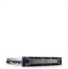
Dell PowerVault DL2200 Hardware Owner's Manual
Dell PowerVault DL2200 Manual
 |
View all Dell PowerVault DL2200 manuals
Add to My Manuals
Save this manual to your list of manuals |
Dell PowerVault DL2200 manual content summary:
- Dell PowerVault DL2200 | Hardware Owner's Manual - Page 1
Dell™ PowerVault™ DL2200 Systems Hardware Owner's Manual Regulatory Model E13S Series Regulatory Type E13S001 - Dell PowerVault DL2200 | Hardware Owner's Manual - Page 2
indicates potential damage to hardware or loss of data if instructions are not followed. WARNING: A WARNING indicates a potential for Dell Inc. is strictly forbidden. Trademarks used in this text: Dell, the DELL logo, and PowerEdge are trademarks of Dell Inc.; Microsoft, Windows, Windows Server - Dell PowerVault DL2200 | Hardware Owner's Manual - Page 3
Contents 1 About Your System 11 Accessing System Features During Startup 11 Front-Panel Features and Indicators 12 Hard-Drive Indicator Patterns 14 Back-Panel Features and Indicators 15 Guidelines for Connecting Optional External Devices 17 NIC Indicator Codes 17 Power Indicator Codes 18 - Dell PowerVault DL2200 | Hardware Owner's Manual - Page 4
Navigation Keys 40 System Setup Options 41 Main Screen 41 Memory Settings Screen 43 Processor Settings Screen 43 Boot Settings Screen 45 Screen 52 System Utilities Screen 53 System and Setup Password Features 53 Using the System Password 53 Using the Setup Password 55 Embedded System - Dell PowerVault DL2200 | Hardware Owner's Manual - Page 5
3 Installing System Components 61 Recommended Tools 61 Inside the System 61 Front Bezel (Optional 63 Removing the Front Bezel 63 Installing the Front Bezel 64 Opening and Closing the System 64 Opening the System 64 Closing the System 65 Cooling Shroud 66 Removing the Cooling Shroud 66 - Dell PowerVault DL2200 | Hardware Owner's Manual - Page 6
the Power Supply Blank 80 Installing the Power Supply Blank 80 System Memory 80 General Memory Module Installation Guidelines 81 Mode-Specific Guidelines 82 Installing Memory Modules 85 Removing Memory Modules 87 Expansion Cards and Expansion-Card Risers 88 Expansion Card Installation - Dell PowerVault DL2200 | Hardware Owner's Manual - Page 7
Installing a VFlash Media Card 103 Removing a VFlash Media Card 103 Processors 103 Removing a Processor 103 Installing a Processor 107 System Battery 108 Replacing the System Battery 108 RAID Battery 111 Removing the RAID Battery 111 Installing the RAID Battery 112 Control Panel Assembly- - Dell PowerVault DL2200 | Hardware Owner's Manual - Page 8
System 132 Troubleshooting a Damaged System 134 Troubleshooting the System Battery 134 Troubleshooting Power Supplies 135 Troubleshooting System Cooling Problems 136 Troubleshooting a Fan 136 Troubleshooting System Memory 137 Troubleshooting a Hard Drive 139 Troubleshooting an Internal Hard - Dell PowerVault DL2200 | Hardware Owner's Manual - Page 9
Testing 149 Selecting Diagnostics Options 149 Viewing Information and Results 150 6 Jumpers and Connectors 151 System Board Jumpers 151 System Board Connectors 152 Disabling a Forgotten Password 154 7 Getting Help 157 Contacting Dell 157 Index 159 Contents 9 - Dell PowerVault DL2200 | Hardware Owner's Manual - Page 10
10 Contents - Dell PowerVault DL2200 | Hardware Owner's Manual - Page 11
controller allows you to access utilities such as embedded system diagnostics. For information on Lifecycle Controller or any of the Lifecycle Controller software components, see the Lifecycle Controller documentation on the Dell Support website at support.dell.com/manuals. Enters the BIOS - Dell PowerVault DL2200 | Hardware Owner's Manual - Page 12
powering on the system, the video monitor can take from several seconds to over 2 minutes to display an image, depending on the amount of memory installed in the system. NOTE: On ACPI-compliant operating systems, turning off the system using the power button causes the system to perform a graceful - Dell PowerVault DL2200 | Hardware Owner's Manual - Page 13
Video connector Description Used to troubleshoot software and device driver errors button only if directed to do so by qualified support personnel or by the operating system's documentation. -out panel for system information including the Express Service tag, embedded NIC MAC address, and iDRAC6 - Dell PowerVault DL2200 | Hardware Owner's Manual - Page 14
Hard-Drive Indicator Patterns Figure 1-2. Hard-Drive Indicators 1 2 1 hard-drive activity indicator (green) 2 hard-drive status indicator (green and amber) Drive-Status Indicator Pattern Blinks green two times per second Off Blinks green, amber, and off Blinks amber four times per second - Dell PowerVault DL2200 | Hardware Owner's Manual - Page 15
device to the system. Connects a VGA display to the system. Dedicated management port for the optional iDRAC6 Enterprise card. Connects an external SD memory card for the optional iDRAC6 Enterprise card. Connect USB devices to the system. The ports are USB 2.0-compliant. Embedded 10/100/1000 NIC - Dell PowerVault DL2200 | Hardware Owner's Manual - Page 16
and back of the system can cause the indicator to blink blue to identify a particular system. Lights amber when the system needs attention due to a problem. The identification buttons on the front and back panels can be used to locate a particular system within a rack. When one of these buttons is - Dell PowerVault DL2200 | Hardware Owner's Manual - Page 17
1 2 1 link indicator 2 activity indicator Indicator Indicator Code Link and activity indicators are off The NIC is not connected to the network. Link indicator is green The NIC is connected to a valid network link at 1000 Mbps. Link indicator is amber The NIC is connected to a valid - Dell PowerVault DL2200 | Hardware Owner's Manual - Page 18
is operational. When the system is on, it also indicates that the power supply is providing DC power to the system. • Amber - Indicates a problem with the power supply. • Alternating green and amber - When hot-adding a power supply, this indicates that the power supply is mismatched with the other - Dell PowerVault DL2200 | Hardware Owner's Manual - Page 19
. operating condition after POST. BIOS checksum failure detected; system is in recovery mode. See "Getting Help" on page 157. Possible processor failure. See "Troubleshooting Processors" on page 144. Memory failure. See "Troubleshooting System Memory" on page 137. Possible expansion card See - Dell PowerVault DL2200 | Hardware Owner's Manual - Page 20
. See "Getting Help" on page 157. Memory configuration See "Troubleshooting System error. Memory" on page 137. Possible system board resource and/or system board hardware failure. See "Getting Help" on page 157. Possible system resource See "Contacting Dell" on configuration error. page 157 - Dell PowerVault DL2200 | Hardware Owner's Manual - Page 21
configuration that supports Advanced ECC Memory Mode. Check other system messages for additional information for possible causes. For memory configuration information, see "General Memory Module Installation Guidelines" on page 81. If the problem persists, see "Troubleshooting System Memory" on page - Dell PowerVault DL2200 | Hardware Owner's Manual - Page 22
. After AC recovery, the optional supports node interleaving. Check other system messages for additional information for possible causes. For memory configuration information, see "General Memory Module Installation Guidelines" on page 81. If the problem persists, see "Troubleshooting System Memory - Dell PowerVault DL2200 | Hardware Owner's Manual - Page 23
mirroring was enabled in the for failure. See system setup program, but "Troubleshooting System the current configuration Memory" on page 137. does not support redundant Reset the memory setting, memory. A memory module if appropriate. See "Using may be faulty. the System Setup Program - Dell PowerVault DL2200 | Hardware Owner's Manual - Page 24
. Retry the BIOS update. If problem persists, see "Getting Help" on page 157. Caution! NVRAM_CLR jumper is NVRAM_CLR jumper installed in the clear setting. is installed on CMOS has been cleared. system board. Please run SETUP. Move the NVRAM_CLR jumper to the default position (pins 3 and - Dell PowerVault DL2200 | Hardware Owner's Manual - Page 25
is available. See "Using the System Setup Program and UEFI Boot Manager" on page 39. Decreasing available memory. Faulty or improperly installed Reseat the memory modules. memory modules. See "Troubleshooting System Memory" on page 137. DIMM configuration on each CPU should match. Invalid - Dell PowerVault DL2200 | Hardware Owner's Manual - Page 26
Shared NIC= . Check the system management software or the System Setup program for NIC settings. If a problem is indicated, see "Troubleshooting a system to stop responding. Run the System Setup program and review the current settings. See "Using the System Setup Program and - Dell PowerVault DL2200 | Hardware Owner's Manual - Page 27
other system power conservation. messages for possible causes. The current memory Ensure that your memory configuration may support configuration supports the only the minimum frequency. higher frequency. See "General Memory Module Installation Guidelines" on page 81. About Your System - Dell PowerVault DL2200 | Hardware Owner's Manual - Page 28
Mirroring mode. See been disabled. "System Memory" on page 80. No boot device available. Faulty or missing hard drive, or hard drive subsystem, or no bootable USB key installed. Use a bootable USB key or hard drive. If the problem persists, see "Troubleshooting a USB Device" on page 130 and - Dell PowerVault DL2200 | Hardware Owner's Manual - Page 29
and 3) and reboot the system. See Figure 6-1 for jumper location. If the problem persists, see "Troubleshooting Expansion Cards" on page 142. Ensure that the memory modules are installed in a valid configuration. See "General Memory Module Installation Guidelines" on page 81. About Your System 29 - Dell PowerVault DL2200 | Hardware Owner's Manual - Page 30
the disk, or the requested connected. sector is defective. See "Troubleshooting a USB Device" on page 130 or "Troubleshooting a memory configuration does not match the setting in BIOS. The BIOS setting has been disabled. Reconfigure the memory modules for Memory Sparing mode. See "System Memory - Dell PowerVault DL2200 | Hardware Owner's Manual - Page 31
added or removed, check the SEL to determine if single-bit or multi-bit errors were detected and replace the faulty memory module. See "Troubleshooting System Memory" on page 137. The following DIMMs should match in geometry: x,x,... The following DIMMs should match in rank count: x,x,... Invalid - Dell PowerVault DL2200 | Hardware Owner's Manual - Page 32
memory module without a Replace the memory thermal sensor is installed in module. See "System the specified memory slot. Memory" on page 80. Time-of-day clock stopped. Faulty battery or faulty chip. See "Troubleshooting configuration command has been entered. User interaction is required to proceed - Dell PowerVault DL2200 | Hardware Owner's Manual - Page 33
) User Guide for instructions on performing a field replacement of the flash memory. Unexpected interrupt in protected mode. Improperly seated memory modules or faulty keyboard/mouse controller chip. Reseat the memory modules. See "Troubleshooting System Memory" on page 137. If the problem - Dell PowerVault DL2200 | Hardware Owner's Manual - Page 34
in 128-bit screen. See "System advanced ECC Memory" on page 80. mode: x,x,x. Warning: A troubleshooting section in "Troubleshooting Your System" on page 129 for any faulty components specified in the SEL. Warning! No micro Micro code update failed. code update loaded for processor n. Update - Dell PowerVault DL2200 | Hardware Owner's Manual - Page 35
this warning, then the replaced component(s) are not supported with this power supply. If Energy Smart power supplies memory modules are installed in a valid configuration. See "General Memory Module Installation Guidelines" on page 81. If the problem persists, see "Troubleshooting System Memory - Dell PowerVault DL2200 | Hardware Owner's Manual - Page 36
Troubleshooting a Hard Drive" on page 139. NOTE: For the full name of an abbreviation or acronym used in this table, see the Glossary on support.dell.com/manuals. Warning Messages A warning message alerts you to a possible problem Messages The system diagnostic utilities may issue messages if - Dell PowerVault DL2200 | Hardware Owner's Manual - Page 37
with your system. • The Lifecycle Controller User Guide provides information about setting up the controller, configuring hardware and firmware, and deploying the operating system. NOTE: Always check for updates on support.dell.com/manuals and read the updates first because they often supersede - Dell PowerVault DL2200 | Hardware Owner's Manual - Page 38
38 About Your System - Dell PowerVault DL2200 | Hardware Owner's Manual - Page 39
mode for installing your operating system: • BIOS boot mode (the default) is the standard BIOS-level boot interface. • Unified Extensible Firmware Interface (UEFI) boot mode is an enhanced 64-bit boot interface based on UEFI specifications that overlays the system BIOS. For more information on this - Dell PowerVault DL2200 | Hardware Owner's Manual - Page 40
. NOTE: After installing a memory upgrade, it is normal for your system to display a message that the system memory size has changed the first In many , left and right arrows fields, you can also type the appropriate value. Exits the System Setup program and restarts the system if any - Dell PowerVault DL2200 | Hardware Owner's Manual - Page 41
Setup program change based on the system configuration. NOTE: The System Setup program defaults are listed under their respective options in the following sections, where applicable. Option System Time System Date Memory Settings Description Sets the time on the system's internal clock. Sets the - Dell PowerVault DL2200 | Hardware Owner's Manual - Page 42
memory modules with preconfigured or customized settings. See "Power Management Screen" on page 48. System Security Displays a screen to configure the system password and setup password Error (Enabled default) Enables the system to halt on errors during POST, which allows the user to observe - Dell PowerVault DL2200 | Hardware Owner's Manual - Page 43
on all systems. Node Interleaving (Disabled default) If this field is Enabled, memory interleaving is supported if a symmetric memory configuration is installed. If Disabled, the system supports Non-Uniform Memory architecture (NUMA) (asymmetric) memory configurations. NOTE: The Node Interleaving - Dell PowerVault DL2200 | Hardware Owner's Manual - Page 44
. Adjacent Cache Line Prefetch (Enabled default) Enables or disables high utilization of sequential memory access. NOTE: Disable this option for applications that require high utilization of random memory access. Hardware Prefetcher (Enabled default) Enables or disables the hardware prefetcher - Dell PowerVault DL2200 | Hardware Owner's Manual - Page 45
Hard-Disk Drive Sequence USB Flash Drive Emulation Type (Auto default) Boot Sequence Retry (Disabled default) Description CAUTION: Switching the boot mode could prevent the system from booting if the operating system was not installed in the same boot mode. If the system operating system supports - Dell PowerVault DL2200 | Hardware Owner's Manual - Page 46
3.0b specification. I/OAT DMA Engine (Disabled default) Enables or disables the I/O acceleration technology (I/OAT). This feature should only be enabled if the hardware and software support I/OAT. Embedded Video Controller (Enabled default) Displays the total amount of video memory available in - Dell PowerVault DL2200 | Hardware Owner's Manual - Page 47
and Off. Serial Port Address (Serial Device 1=COM1, Serial Device 2=COM2 default) Sets the serial port addresses for the two serial devices. NOTE: Only Serial redirection and the serial device. Failsafe Baud Rate (115200 default) Displays the failsafe baud rate used for console redirection. - Dell PowerVault DL2200 | Hardware Owner's Manual - Page 48
(Active Power Controller default) Options are OS Control and the memory power to Maximum Performance. The BIOS sets the processor performance based on processor utilization. • Password Description Displays the current status of the password security feature and allows a new system password - Dell PowerVault DL2200 | Hardware Owner's Manual - Page 49
Password Password Status (Unlocked default) TPM Security (Off default) TPM Activation (No Change default) TPM Clear (No default) Description Restricts access to the System Setup program by using a setup password. NOTE: For more information, see "Using the System Password (all user settings for - Dell PowerVault DL2200 | Hardware Owner's Manual - Page 50
when the system restarts after power is (Immediate default) restored. Options are Immediate (no delay), Random (between 30 to 240 seconds for iDRAC, or 45 to 240 seconds for BMC), or User Defined. User Defined Delay Determines the user defined AC Recovery Delay. Exit Screen Press to exit - Dell PowerVault DL2200 | Hardware Owner's Manual - Page 51
Entering the UEFI Boot Manager NOTE: Operating systems must be 64-bit UEFI-compatible (for example, Microsoft® Windows Server® 2008 x 64 version) to be installed from the UEFI boot mode. DOS and 32-bit operating systems can only be installed from the BIOS boot - Dell PowerVault DL2200 | Hardware Owner's Manual - Page 52
Option Continue UEFI Boot Settings System Utilities Description The system attempts to boot to devices one-time boot option. Enables you to access the System Setup program, System Services (USC), Diagnostics, and BIOS-level boot options. UEFI Boot Settings Screen Option Add - Dell PowerVault DL2200 | Hardware Owner's Manual - Page 53
Screen Option System Setup System Services BIOS Boot Manager Reboot System Description Accesses the System Setup program without rebooting. Restarts the system and accesses the controller, which enables you to run utilities such as system diagnostics. Accesses the BIOS-level boot options list - Dell PowerVault DL2200 | Hardware Owner's Manual - Page 54
, press to move to another field, or press prior to completing step 5. 4 Press . 5 To confirm your password, type it a second time and press . System Password changes to Enabled. Exit the System Setup program and begin using your system. 6 Either reboot the system now for - Dell PowerVault DL2200 | Hardware Owner's Manual - Page 55
displays a message and prompts you to re-enter your password. You have three attempts to enter the correct password. After the third unsuccessful attempt, the system displays an error message that the system has halted and must be shut down manually using the power button. Even after you shut down - Dell PowerVault DL2200 | Hardware Owner's Manual - Page 56
can be the same as the system password. If the two passwords are different, the setup password can be used as an alternate system password. The system password cannot be used in place of the setup password. You can use up to 32 characters in your password. As you type, placeholders appear in the - Dell PowerVault DL2200 | Hardware Owner's Manual - Page 57
the Lifecycle Controller User Guide on the Dell Support website at support.dell.com/manuals. Baseboard Management Controller Configuration NOTE: If an iDRAC6 Express card is installed on the system, the Baseboard Management Controller (BMC) utility is replaced by the iDRAC6 utility. The BMC enables - Dell PowerVault DL2200 | Hardware Owner's Manual - Page 58
allows you to view and set parameters for the optional iDRAC6 and for the managed server. The iDRAC Configuration Utility enables you to: • Configure, enable, or disable the iDRAC6 local area network (LAN) through the dedicated iDRAC6 Enterprise card port or the embedded NICs. • Enable or disable - Dell PowerVault DL2200 | Hardware Owner's Manual - Page 59
If your operating system begins to load before you press , allow the system to finish booting, restart your system and try again. Using the System Setup Program and UEFI Boot Manager 59 - Dell PowerVault DL2200 | Hardware Owner's Manual - Page 60
60 Using the System Setup Program and UEFI Boot Manager - Dell PowerVault DL2200 | Hardware Owner's Manual - Page 61
only perform troubleshooting and simple repairs as authorized in your product documentation, or as directed by the online or telephone service and support team. Damage due to servicing that is not authorized by Dell is not covered by your warranty. Read and follow the safety instructions that came - Dell PowerVault DL2200 | Hardware Owner's Manual - Page 62
Figure 3-1. Inside the System 5 4 3 2 1 6 10 1 cooling fan 3 expansion-card riser 5 cooling shroud 7 memory modules (8) 9 SAS backplane 7 8 9 2 internal hard drives (2) 4 power supply bays (2) 6 heat sink/processor (2) 8 system cooling fans (4) 10 hard drives (12) 62 Installing System Components - Dell PowerVault DL2200 | Hardware Owner's Manual - Page 63
Front Bezel (Optional) Removing the Front Bezel 1 Using the system key, unlock the bezel. 2 Lift the release latch next to the key lock. 3 Rotate the left end of the bezel away from the front panel. 4 Unhook the right end of the bezel and pull the bezel away from the system. Figure 3-2. Removing and - Dell PowerVault DL2200 | Hardware Owner's Manual - Page 64
only perform troubleshooting and simple repairs as authorized in your product documentation, or as directed by the online or telephone service and support team. Damage due to servicing that is not authorized by Dell is not covered by your warranty. Read and follow the safety instructions that came - Dell PowerVault DL2200 | Hardware Owner's Manual - Page 65
Figure 3-3. Opening and Closing the System 2 1 1 system cover latch 2 latch release lock Closing the System 1 Lift the latch on the system cover. 2 Place the cover onto the chassis and offset it slightly back so that the two hooks on the back edge of the cover fit the corresponding tabs on the - Dell PowerVault DL2200 | Hardware Owner's Manual - Page 66
only perform troubleshooting and simple repairs as authorized in your product documentation, or as directed by the online or telephone service and support team. Damage due to servicing that is not authorized by Dell is not covered by your warranty. Read and follow the safety instructions that came - Dell PowerVault DL2200 | Hardware Owner's Manual - Page 67
only perform troubleshooting and simple repairs as authorized in your product documentation, or as directed by the online or telephone service and support team. Damage due to servicing that is not authorized by Dell is not covered by your warranty. Read and follow the safety instructions that came - Dell PowerVault DL2200 | Hardware Owner's Manual - Page 68
Figure 3-5. Removing or Installing a Hard-Drive Blank 1 2 1 hard-drive blank 2 release lever Installing a Hard-Drive Blank Align the hard-drive blank with the drive bay and insert the blank into the drive bay until the release lever clicks into place. See Figure 3-5. Removing a Hot-Swap Hard - Dell PowerVault DL2200 | Hardware Owner's Manual - Page 69
can damage the partially installed carrier's shield spring and make it unusable. CAUTION: To prevent data loss, ensure that your operating system supports hot-swap drive installation. See the documentation supplied with the operating system. CAUTION: Combining SATA and SAS hard drives in the same - Dell PowerVault DL2200 | Hardware Owner's Manual - Page 70
4 With the lever on the hard drive carrier open, slide the hard drive into the drive bay until the carrier contacts the backplane. See Figure 3-6. 5 Close the handle to lock the drive in place. Removing a Hard Drive From a Hard-Drive Carrier Remove the screws from the slide rails on the hard-drive - Dell PowerVault DL2200 | Hardware Owner's Manual - Page 71
only perform troubleshooting and simple repairs as authorized in your product documentation, or as directed by the online or telephone service and support team. Damage due to servicing that is not authorized by Dell is not covered by your warranty. Read and follow the safety instructions that came - Dell PowerVault DL2200 | Hardware Owner's Manual - Page 72
Figure 3-8. Removing and Installing an Internal Hard Drive Bay 2 3 1 4 1 internal hard drives (2) 3 internal hard drive bay 2 release latch 4 support bracket 72 Installing System Components - Dell PowerVault DL2200 | Hardware Owner's Manual - Page 73
only perform troubleshooting and simple repairs as authorized in your product documentation, or as directed by the online or telephone service and support team. Damage due to servicing that is not authorized by Dell is not covered by your warranty. Read and follow the safety instructions that came - Dell PowerVault DL2200 | Hardware Owner's Manual - Page 74
Drive Bay 3 2 1 4 1 internal hard drive bay 3 screws (4) * 2 release latch 4 internal hard drive *Screws are supplied along with the hard drives ordered from Dell. Installing a Hard Drive Into a Hard-Drive Bay 1 Insert the hard drive into the internal hard-drive bay with the connector end of the - Dell PowerVault DL2200 | Hardware Owner's Manual - Page 75
only perform troubleshooting and simple repairs as authorized in your product documentation, or as directed by the online or telephone service and support team. Damage due to servicing that is not authorized by Dell is not covered by your warranty. Read and follow the safety instructions that came - Dell PowerVault DL2200 | Hardware Owner's Manual - Page 76
Figure 3-10. Removing and Installing a Fan 2 1 3 1 fans (5) 3 fan power cable 2 release tab 76 Installing System Components - Dell PowerVault DL2200 | Hardware Owner's Manual - Page 77
troubleshooting and simple repairs as authorized in your product documentation, or as directed by the online or telephone service and support team. Damage due to servicing that is not authorized by Dell is not covered by your warranty. Read and follow the safety instructions through the guides on the - Dell PowerVault DL2200 | Hardware Owner's Manual - Page 78
only perform troubleshooting and simple repairs as authorized in your product documentation, or as directed by the online or telephone service and support team. Damage due to servicing that is not authorized by Dell is not covered by your warranty. Read and follow the safety instructions that came - Dell PowerVault DL2200 | Hardware Owner's Manual - Page 79
Figure 3-11. Removing and Installing a Power Supply 1 2 1 power supply 3 velcro strap 4 3 2 power supply handle 4 release latch Installing a Power Supply 1 Verify that both power supplies are of the same type and have the same maximum output power. NOTE: The maximum output power (shown in - Dell PowerVault DL2200 | Hardware Owner's Manual - Page 80
power supply blank, align the blank with the power supply bay and insert the blank into the chassis until it clicks into place. System Memory Your system supports DDR3 registered DIMMs (RDIMMs) or unbuffered ECC DIMMs (UDIMMs). Single and dual-rank DIMMs can be 1067- or 1333-MHz, and quad-rank DIMMs - Dell PowerVault DL2200 | Hardware Owner's Manual - Page 81
that use x4 or x8 DRAM device widths. • The memory speed of each channel depends on the memory configuration: - For single or dual-rank memory modules: • One memory module per channel supports up to 1333 MHz. • Two memory modules per channel supports up to 1067 MHz. Installing System Components 81 - Dell PowerVault DL2200 | Hardware Owner's Manual - Page 82
at the speed of the slowest installed memory module(s). Mode-Specific Guidelines Three memory channels are allocated to each processor. The number of channels used and the allowable configurations depend on the memory mode selected. Advanced ECC (Lockstep) Mode Support In this configuration, the two - Dell PowerVault DL2200 | Hardware Owner's Manual - Page 83
(GB) (GB) 1 all 2 3 4 2 all 4 6 8 4 all 8 12 16 8 all 16 24 32 16 all 32 48 64 Dual Processor Physical Available Memory Memory (GB) (GB) 2 all 4 6 8 4 all 8 12 16 8 all 16 24 32 16 all 32 48 64 32 all 64 96 128 Installing System Components 83 - Dell PowerVault DL2200 | Hardware Owner's Manual - Page 84
Sockets 123 XX XX XX XX XX XX XX XX Single Processor Dual Processor Physical Available Physical Available Memory Memory Memory Memory (GB) (GB) (GB) (GB) 4 all 8 all 8 all 16 all 16 all 32 all 32 all 64 all 4 2 8 4 8 4 16 8 16 8 32 16 32 16 64 32 1. - Dell PowerVault DL2200 | Hardware Owner's Manual - Page 85
only perform troubleshooting and simple repairs as authorized in your product documentation, or as directed by the online or telephone service and support team. Damage due to servicing that is not authorized by Dell is not covered by your warranty. Read and follow the safety instructions that came - Dell PowerVault DL2200 | Hardware Owner's Manual - Page 86
module in the socket in only one way. 8 Press down on the memory module with your thumbs to lock the memory module into the socket. When the memory module is properly seated in the socket, the ejectors on the memory module socket snap in place. 9 Repeat step 5 through step 8 of this procedure to - Dell PowerVault DL2200 | Hardware Owner's Manual - Page 87
only perform troubleshooting and simple repairs as authorized in your product documentation, or as directed by the online or telephone service and support team. Damage due to servicing that is not authorized by Dell is not covered by your warranty. Read and follow the safety instructions that came - Dell PowerVault DL2200 | Hardware Owner's Manual - Page 88
the memory module. 6 Replace the cooling shroud. See "Installing the Cooling Shroud" on page 67. 7 Close the system. See "Closing the System" on page 65. 8 Reconnect the system and peripherals to their power sources, and turn them on. Expansion Cards and Expansion-Card Risers Your system supports up - Dell PowerVault DL2200 | Hardware Owner's Manual - Page 89
storage controller. • Table 3 provides a guide for installing expansion cards to ensure proper cooling 6 HPCC 7 Fibre Channel 8 10 Gb NIC 9 All other NICs 10 All other Dell internal storage cards 11 Non-Dell storage cards * When available Slot Priority 1, 2 3, 2 3, 2 3, 2 3, 2 2, 1 2, - Dell PowerVault DL2200 | Hardware Owner's Manual - Page 90
only perform troubleshooting and simple repairs as authorized in your product documentation, or as directed by the online or telephone service and support team. Damage due to servicing that is not authorized by Dell is not covered by your warranty. Read and follow the safety instructions that came - Dell PowerVault DL2200 | Hardware Owner's Manual - Page 91
Figure 3-13. Removing and Installing an Expansion Card 2 1 3 1 expansion-card riser 3 expansion card 2 expansion-card latch 9 Connect any cables to the expansion card. 10 Close the system. See "Closing the System" on page 65. 11 Reconnect the system to its electrical outlet and turn the system - Dell PowerVault DL2200 | Hardware Owner's Manual - Page 92
only perform troubleshooting and simple repairs as authorized in your product documentation, or as directed by the online or telephone service and support team. Damage due to servicing that is not authorized by Dell is not covered by your warranty. Read and follow the safety instructions that came - Dell PowerVault DL2200 | Hardware Owner's Manual - Page 93
only perform troubleshooting and simple repairs as authorized in your product documentation, or as directed by the online or telephone service and support team. Damage due to servicing that is not authorized by Dell is not covered by your warranty. Read and follow the safety instructions that came - Dell PowerVault DL2200 | Hardware Owner's Manual - Page 94
only perform troubleshooting and simple repairs as authorized in your product documentation, or as directed by the online or telephone service and support team. Damage due to servicing that is not authorized by Dell is not covered by your warranty. Read and follow the safety instructions that came - Dell PowerVault DL2200 | Hardware Owner's Manual - Page 95
only perform troubleshooting and simple repairs as authorized in your product documentation, or as directed by the online or telephone service and support team. Damage due to servicing that is not authorized by Dell is not covered by your warranty. Read and follow the safety instructions that came - Dell PowerVault DL2200 | Hardware Owner's Manual - Page 96
7 Bend both the card-edge guides outward and pull the storage controller card out of the connector. Figure 3-15. Installing and Removing the Storage Controller Card 2 1 3 4 5 6 1 storage connector 3 storage controller card 5 - Dell PowerVault DL2200 | Hardware Owner's Manual - Page 97
only perform troubleshooting and simple repairs as authorized in your product documentation, or as directed by the online or telephone service and support team. Damage due to servicing that is not authorized by Dell is not covered by your warranty. Read and follow the safety instructions that came - Dell PowerVault DL2200 | Hardware Owner's Manual - Page 98
only perform troubleshooting and simple repairs as authorized in your product documentation, or as directed by the online or telephone service and support team. Damage due to servicing that is not authorized by Dell is not covered by your warranty. Read and follow the safety instructions that came - Dell PowerVault DL2200 | Hardware Owner's Manual - Page 99
only perform troubleshooting and simple repairs as authorized in your product documentation, or as directed by the online or telephone service and support team. Damage due to servicing that is not authorized by Dell is not covered by your warranty. Read and follow the safety instructions that came - Dell PowerVault DL2200 | Hardware Owner's Manual - Page 100
only perform troubleshooting and simple repairs as authorized in your product documentation, or as directed by the online or telephone service and support team. Damage due to servicing that is not authorized by Dell is not covered by your warranty. Read and follow the safety instructions that came - Dell PowerVault DL2200 | Hardware Owner's Manual - Page 101
Figure 3-17. Removing and Installing an iDRAC6 Enterprise Card 1 2 3 6 4 5 1 VFlash SD card 3 iDRAC6 Enterprise card 5 retention standoff tabs (2) 2 VFlash media slot 4 retention standoff posts (2) 6 iDRAC6 Enterprise card connector 7 If applicable, install the VFlash media card. See " - Dell PowerVault DL2200 | Hardware Owner's Manual - Page 102
only perform troubleshooting and simple repairs as authorized in your product documentation, or as directed by the online or telephone service and support team. Damage due to servicing that is not authorized by Dell is not covered by your warranty. Read and follow the safety instructions that came - Dell PowerVault DL2200 | Hardware Owner's Manual - Page 103
only perform troubleshooting and simple repairs as authorized in your product documentation, or as directed by the online or telephone service and support team. Damage due to servicing that is not authorized by Dell is not covered by your warranty. Read and follow the safety instructions that came - Dell PowerVault DL2200 | Hardware Owner's Manual - Page 104
CAUTION: Never remove the heat sink from a processor unless you intend to remove the processor. The heat sink is necessary to maintain proper thermal conditions. 5 Using a #2 Phillips screwdriver, loosen one of the heat-sink retention screws. See Figure 3-18. 6 Wait 30 seconds for the heat sink to - Dell PowerVault DL2200 | Hardware Owner's Manual - Page 105
Figure 3-18. Installing and Removing the Heat Sink 1 2 1 heat sink heat-sink 2 retention screws (4) 10 Rotate the processor shield upward and out of the way. See Figure 3-19. 11 Lift the processor out of the socket and leave the release lever up so that the socket is ready for the new processor. - Dell PowerVault DL2200 | Hardware Owner's Manual - Page 106
Figure 3-19. Installing and Removing a Processor 1 2 3 6 1 processor 3 notch in processor 5 ZIF socket 4 5 2 processor shield 4 socket key 6 socket-release lever 106 Installing System Components - Dell PowerVault DL2200 | Hardware Owner's Manual - Page 107
only perform troubleshooting and simple repairs as authorized in your product documentation, or as directed by the online or telephone service and support team. Damage due to servicing that is not authorized by Dell is not covered by your warranty. Read and follow the safety instructions that came - Dell PowerVault DL2200 | Hardware Owner's Manual - Page 108
only perform troubleshooting and simple repairs as authorized in your product documentation, or as directed by the online or telephone service and support team. Damage due to servicing that is not authorized by Dell is not covered by your warranty. Read and follow the safety instructions that came - Dell PowerVault DL2200 | Hardware Owner's Manual - Page 109
socket. See "Jumpers and Connectors" on page 151. CAUTION: To avoid damage to the battery connector, you must firmly support the connector while installing or removing a battery. 8 Support the battery connector by firmly holding the positive side of the connector. Installing System Components 109 - Dell PowerVault DL2200 | Hardware Owner's Manual - Page 110
battery toward the negative side of the connector and lift it up out of the securing tab at the negative side of the connector. 10 Support the battery connector by pressing down firmly on the positive side of the connector. 11 Hold the new battery with the "+" facing the plastic connector - Dell PowerVault DL2200 | Hardware Owner's Manual - Page 111
only perform troubleshooting and simple repairs as authorized in your product documentation, or as directed by the online or telephone service and support team. Damage due to servicing that is not authorized by Dell is not covered by your warranty. Read and follow the safety instructions that came - Dell PowerVault DL2200 | Hardware Owner's Manual - Page 112
only perform troubleshooting and simple repairs as authorized in your product documentation, or as directed by the online or telephone service and support team. Damage due to servicing that is not authorized by Dell is not covered by your warranty. Read and follow the safety instructions that came - Dell PowerVault DL2200 | Hardware Owner's Manual - Page 113
6 Remove the power button board and power button from the control-panel module. Figure 3-22. Removing and Installing the Control Panel-LED 2 1 3 4 5 1 bracket 3 power button board 5 control-panel module 2 control-panel cable 4 power button Installing System Components 113 - Dell PowerVault DL2200 | Hardware Owner's Manual - Page 114
only perform troubleshooting and simple repairs as authorized in your product documentation, or as directed by the online or telephone service and support team. Damage due to servicing that is not authorized by Dell is not covered by your warranty. Read and follow the safety instructions that came - Dell PowerVault DL2200 | Hardware Owner's Manual - Page 115
only perform troubleshooting and simple repairs as authorized in your product documentation, or as directed by the online or telephone service and support team. Damage due to servicing that is not authorized by Dell is not covered by your warranty. Read and follow the safety instructions that came - Dell PowerVault DL2200 | Hardware Owner's Manual - Page 116
Figure 3-23. Removing and Installing the Front-Panel I/O Module 1 2 3 4 1 front-panel I/O cable 3 front-panel I/O module 2 bracket 4 mounting screws (3) 116 Installing System Components - Dell PowerVault DL2200 | Hardware Owner's Manual - Page 117
only perform troubleshooting and simple repairs as authorized in your product documentation, or as directed by the online or telephone service and support team. Damage due to servicing that is not authorized by Dell is not covered by your warranty. Read and follow the safety instructions that came - Dell PowerVault DL2200 | Hardware Owner's Manual - Page 118
5 Disconnect the power cable from the end of the SAS backplane. 6 Disconnect the SAS data cables from the backplane. 7 Disconnect the USB cable and the control-panel cable. CAUTION: Handle the cables gently to prevent damage. 8 Disconnect the internal hard-drive cables. 9 While pressing the two blue - Dell PowerVault DL2200 | Hardware Owner's Manual - Page 119
Figure 3-24. Removing and Installing a SAS Backplane 3 4 5 6 2 7 1 8 9 10 1 SAS backplane 3 SAS cables 5 USB memory key connector 7 control panel cable 9 USB cable 2 backplane retention latches (2) 4 control panel module cable 6 SAS backplane power cable 8 internal hard drive cables (2) 10 - Dell PowerVault DL2200 | Hardware Owner's Manual - Page 120
only perform troubleshooting and simple repairs as authorized in your product documentation, or as directed by the online or telephone service and support team. Damage due to servicing that is not authorized by Dell is not covered by your warranty. Read and follow the safety instructions that came - Dell PowerVault DL2200 | Hardware Owner's Manual - Page 121
only perform troubleshooting and simple repairs as authorized in your product documentation, or as directed by the online or telephone service and support team. Damage due to servicing that is not authorized by Dell is not covered by your warranty. Read and follow the safety instructions that came - Dell PowerVault DL2200 | Hardware Owner's Manual - Page 122
Figure 3-25. Removing and Installing the Power Distribution Board 3 4 2 1 6 1 screws (3) 3 power-interposer board 5 power-distribution board 5 2 power supply connector 4 blue tab 6 fan module cable connector 122 Installing System Components - Dell PowerVault DL2200 | Hardware Owner's Manual - Page 123
only perform troubleshooting and simple repairs as authorized in your product documentation, or as directed by the online or telephone service and support team. Damage due to servicing that is not authorized by Dell is not covered by your warranty. Read and follow the safety instructions that came - Dell PowerVault DL2200 | Hardware Owner's Manual - Page 124
only perform troubleshooting and simple repairs as authorized in your product documentation, or as directed by the online or telephone service and support team. Damage due to servicing that is not authorized by Dell is not covered by your warranty. Read and follow the safety instructions that came - Dell PowerVault DL2200 | Hardware Owner's Manual - Page 125
CAUTION: Do not lift the system board assembly by grasping a memory module, processor, or other components. 12 Grasp the system board assembly by the edges and lift the system board assembly away from the chassis. See - Dell PowerVault DL2200 | Hardware Owner's Manual - Page 126
troubleshooting and simple repairs as authorized in your product documentation, or as directed by the online or telephone service and support team. Damage due to servicing that is not authorized by Dell is not covered by your warranty. Read and follow the safety instructions grasping a memory module, - Dell PowerVault DL2200 | Hardware Owner's Manual - Page 127
13 If applicable, install the iDRAC6 Enterprise card. See "Installing an iDRAC6 Enterprise Card" on page 100. 14 If applicable, install the iDRAC6 Express card. See "Installing an iDRAC6 Express Card" on page 98. 15 Replace the cooling shroud. See "Installing the Cooling Shroud" on page 67. 16 Close - Dell PowerVault DL2200 | Hardware Owner's Manual - Page 128
128 Installing System Components - Dell PowerVault DL2200 | Hardware Owner's Manual - Page 129
service and support team. Damage due to servicing that is not authorized by Dell is not covered by your warranty. Read and follow the safety instructions that came with the product. Troubleshooting UEFI Boot Manager" on page 39. • Invalid memory configurations could cause the system to halt at - Dell PowerVault DL2200 | Hardware Owner's Manual - Page 130
the problem is resolved, replace the faulty keyboard/mouse. If the problem is not resolved, proceed to the next step to begin troubleshooting the for instructions on setting the NVRAM_CLR jumper inside your system and restoring the BIOS to the default settings. 130 Troubleshooting Your System - Dell PowerVault DL2200 | Hardware Owner's Manual - Page 131
device. If the problem persists, replace the device. If all troubleshooting fails, see "Getting Help" on page 157. Troubleshooting a Serial I/O Device network driver files might be damaged or missing. Remove and reinstall the drivers if applicable. See the NIC's documentation. Troubleshooting Your - Dell PowerVault DL2200 | Hardware Owner's Manual - Page 132
only perform troubleshooting and simple repairs as authorized in your product documentation, or as directed by the online or telephone service and support team. Damage due to servicing that is not authorized by Dell is not covered by your warranty. Read and follow the safety instructions that came - Dell PowerVault DL2200 | Hardware Owner's Manual - Page 133
iDRAC6 Express card • iDRAC6 Enterprise card • Power supplies • Fans • Processors and heat sinks • Memory modules 4 Let the system dry thoroughly for at least 24 hours. 5 Reinstall the components you removed 147. If the tests fail, see "Getting Help" on page 157. Troubleshooting Your System 133 - Dell PowerVault DL2200 | Hardware Owner's Manual - Page 134
troubleshooting and simple repairs as authorized in your product documentation, or as directed by the online or telephone service and support team. Damage due to servicing that is not authorized by Dell is not covered by your warranty. Read and follow the safety instructions sinks • Memory modules • - Dell PowerVault DL2200 | Hardware Owner's Manual - Page 135
only perform troubleshooting and simple repairs as authorized in your product documentation, or as directed by the online or telephone service and support team. Damage due to servicing that is not authorized by Dell is not covered by your warranty. Read and follow the safety instructions that came - Dell PowerVault DL2200 | Hardware Owner's Manual - Page 136
only perform troubleshooting and simple repairs as authorized in your product documentation, or as directed by the online or telephone service and support team. Damage due to servicing that is not authorized by Dell is not covered by your warranty. Read and follow the safety instructions that came - Dell PowerVault DL2200 | Hardware Owner's Manual - Page 137
only perform troubleshooting and simple repairs as authorized in your product documentation, or as directed by the online or telephone service and support team. Damage due to servicing that is not authorized by Dell is not covered by your warranty. Read and follow the safety instructions that came - Dell PowerVault DL2200 | Hardware Owner's Manual - Page 138
Setup program and check the system memory setting. See "Memory Settings Screen" on page 43. If the problem is not resolved, proceed with the indicates a specific memory module as faulty, swap or replace the module. 17 To troubleshoot an unspecified faulty memory module, replace the memory module in - Dell PowerVault DL2200 | Hardware Owner's Manual - Page 139
service and support team. Damage due to servicing that is not authorized by Dell is not covered by your warranty. Read and follow the safety instructions that came with the product. CAUTION: This troubleshooting Drive" on page 68 d Exit the configuration utility and allow the system to boot to the - Dell PowerVault DL2200 | Hardware Owner's Manual - Page 140
service and support team. Damage due to servicing that is not authorized by Dell is not covered by your warranty. Read and follow the safety instructions that came with the product. CAUTION: This troubleshooting Bay" on page 71 d Exit the configuration utility and allow the system to boot to the operating - Dell PowerVault DL2200 | Hardware Owner's Manual - Page 141
configuration utility troubleshooting and simple repairs as authorized in your product documentation, or as directed by the online or telephone service and support team. Damage due to servicing that is not authorized by Dell is not covered by your warranty. Read and follow the safety instructions - Dell PowerVault DL2200 | Hardware Owner's Manual - Page 142
properly connected and, if applicable, the memory module on the PERC card is properly service and support team. Damage due to servicing that is not authorized by Dell is not covered by your warranty. Read and follow the safety instructions that came with the product. NOTE: When troubleshooting - Dell PowerVault DL2200 | Hardware Owner's Manual - Page 143
the system to the electrical outlet, and turn on the system and attached peripherals. 9 If problem is not resolved, turn off the system and attached peripherals, and disconnect the system from the electrical . If the tests fail, see "Getting Help" on page 157. Troubleshooting Your System 143 - Dell PowerVault DL2200 | Hardware Owner's Manual - Page 144
only perform troubleshooting and simple repairs as authorized in your product documentation, or as directed by the online or telephone service and support team. Damage due to servicing that is not authorized by Dell is not covered by your warranty. Read and follow the safety instructions that came - Dell PowerVault DL2200 | Hardware Owner's Manual - Page 145
processor 1 with processor 2. See "Installing a Processor" on page 107. 17 Repeat step 11 through step 13. If you have tested both the processors and the problem persists, the system board is faulty. See "Getting Help" on page 157. Troubleshooting Your System 145 - Dell PowerVault DL2200 | Hardware Owner's Manual - Page 146
146 Troubleshooting Your System - Dell PowerVault DL2200 | Hardware Owner's Manual - Page 147
diagnostics, see the Dell Online Diagnostics User's Guide. The embedded system diagnostics can be launched using Lifecycle Controller. For more information about using the controller, see Lifecycle Controller documentation on the Dell Support website at support.dell.com/manuals. Embedded System - Dell PowerVault DL2200 | Hardware Owner's Manual - Page 148
an error is detected or terminate testing when a user-defined error limit is reached • View help messages can use the system diagnostics to help identify the problem. Running the Embedded System Diagnostics You can run the specific diagnostics tests or to exit. 148 Running the System Diagnostics - Dell PowerVault DL2200 | Hardware Owner's Manual - Page 149
Customize window allows you to select the device(s) to be tested, select specific options for testing, and view the test results. Selecting Devices for a device: • Non-Interactive Tests Only-Runs only tests that require no user intervention. • Quick Tests Only-Runs only the quick tests on the device - Dell PowerVault DL2200 | Hardware Owner's Manual - Page 150
• Test Iterations-Selects the number of times the test is run. • Log output file pathname-Enables you to specify the USB memory key where the test log file is saved. You cannot save the file to a hard drive. Viewing Information and Results The following tabs in the - Dell PowerVault DL2200 | Hardware Owner's Manual - Page 151
Jumpers and Connectors This section provides specific information about the system jumpers. It System Board Jumper Settings Jumper PWRD_EN NVRAM_CLR Setting (default) (default) Description The password feature is enabled (pins 2-4) The password feature is disabled, and iDRAC6 local access is - Dell PowerVault DL2200 | Hardware Owner's Manual - Page 152
System Board Connectors See Figure 6-1 and Table 6-2 for the location and description of the system board connectors. Figure 6-1. System Board Connectors 1 2 21 20 19 18 17 16 15 14 13 12 11 10 9 8 7 3 4 6 5 152 Jumpers and Connectors - Dell PowerVault DL2200 | Hardware Owner's Manual - Page 153
1 5 FAN1 Cooling fan 1 connector 6 FAN2 Cooling fan 2 connector 7 A3 Memory module slot A3 (white release lever) A2 Memory module slot A2 (white release lever) A1 Memory module slot A1 (white release lever) A4 Memory module slot A4 8 FAN3 Cooling fan 3 connector 9 BATTERY System - Dell PowerVault DL2200 | Hardware Owner's Manual - Page 154
only perform troubleshooting and simple repairs as authorized in your product documentation, or as directed by the online or telephone service and support team. Damage due to servicing that is not authorized by Dell is not covered by your warranty. Read and follow the safety instructions that came - Dell PowerVault DL2200 | Hardware Owner's Manual - Page 155
the system from the electrical outlet. 7 Open the system. See "Opening the System" on page 64. 8 Move the password jumper back to the enabled position to restore the password function. See Table 6-1. 9 Close the system. See "Closing the System" on page 65. 10 Reconnect your system and peripherals - Dell PowerVault DL2200 | Hardware Owner's Manual - Page 156
156 Jumpers and Connectors - Dell PowerVault DL2200 | Hardware Owner's Manual - Page 157
, or Dell product catalog. Dell provides several online and telephone-based support and service options. Availability varies by country and product, and some services may not be available in your area. To contact Dell for sales, technical support, or customer service issues: 1 Visit support.dell.com - Dell PowerVault DL2200 | Hardware Owner's Manual - Page 158
158 Getting Help - Dell PowerVault DL2200 | Hardware Owner's Manual - Page 159
ECC memory mode, 82 B back-panel features, 15 batteries troubleshooting, 134 battery troubleshooting the RAID card battery, 141 battery (system) replacing, 108 bezel, 63 blank hard drive, 67 power supply, 80 BMC configuring, 57 C connectors system board, 152 USB, 12 video, 12 contacting Dell, 157 - Dell PowerVault DL2200 | Hardware Owner's Manual - Page 160
devices, 17 expansion card installation, 88 memory installation, 81 H hard drive troubleshooting, 139-140 hard drives (hot-swappable) installing, 69 heat sink, 105 I iDRAC card installing, 98, 100 system port, 15 iDRAC Configuration Utility - Dell PowerVault DL2200 | Hardware Owner's Manual - Page 161
error messages, 40 system, 21 warning, 36 N NIC indicators, 17 NICs back-panel connectors, 15 troubleshooting, 131 O Optimizer memory mode, 82 P password setup, 55 system, 53 passwords disabling, 154 phone numbers, 157 POST accessing system features, 11 power indicators, 12, 18 power supplies - Dell PowerVault DL2200 | Hardware Owner's Manual - Page 162
92 front-panel IO module, 115 hard drive blank, 67 memory modules, 87 power supply, 78 power supply blank, 80 troubleshooting, 141 SATA hard drive. See hard drive. securing your system, 48, 54 setup password, 55 slots See expansion slots. startup accessing system features, 11 support contacting Dell - Dell PowerVault DL2200 | Hardware Owner's Manual - Page 163
, 52 System Utilities screen, 53 UEFI Boot Settings screen, 52 Unified Server Configurator Lifecyle Controller, 57 upgrades processor, 103 USB front-panel connectors, 12 USB device back-panel connectors, 15 V video back-panel connector, 15 front-panel connectors, 12 troubleshooting, 130 W warning - Dell PowerVault DL2200 | Hardware Owner's Manual - Page 164
164 Index
-
 1
1 -
 2
2 -
 3
3 -
 4
4 -
 5
5 -
 6
6 -
 7
7 -
8
-
9
-
10
-
11
-
12
-
13
-
14
-
15
-
16
-
17
-
18
-
19
-
20
-
21
-
22
-
23
-
24
-
25
-
26
-
27
-
28
-
29
-
30
-
31
-
32
-
33
-
34
-
35
-
36
-
37
-
38
-
39
-
40
-
41
-
42
-
43
-
44
-
45
-
46
-
47
-
48
-
49
-
50
-
51
-
52
-
53
-
54
-
55
-
56
-
57
-
58
-
59
-
60
-
61
-
62
-
63
-
64
-
65
-
66
-
67
-
68
-
69
-
70
-
71
-
72
-
73
-
74
-
75
-
76
-
77
-
78
-
79
-
80
-
81
-
82
-
83
-
84
-
85
-
86
-
87
-
88
-
89
-
90
-
91
-
92
-
93
-
94
-
95
-
96
-
97
-
98
-
99
-
100
-
101
-
102
-
103
-
104
-
105
-
106
-
107
-
108
-
109
-
110
-
111
-
112
-
113
-
114
-
115
-
116
-
117
-
118
-
119
-
120
-
121
-
122
-
123
-
124
-
125
-
126
-
127
-
128
-
129
-
130
-
131
-
132
-
133
-
134
-
135
-
136
-
137
-
138
-
139
-
140
-
141
-
142
-
143
-
144
-
145
-
146
-
147
-
148
-
149
-
150
-
151
-
152
-
153
-
154
-
155
-
156
-
157
-
158
-
159
-
160
-
161
-
162
-
163
-
164
 |
 |

Dell™ PowerVault™
DL2200 Systems
Hardware Owner’s
Manual
Regulatory Model E13S Series
Regulatory Type E13S001