Dell PowerVault NX3500 Administrator's Guide - Page 25
PowerVault MD Storage, BPS, Cache, iSCSI Connections, RAID 1, and RAID 50.
 |
View all Dell PowerVault NX3500 manuals
Add to My Manuals
Save this manual to your list of manuals |
Page 25 highlights
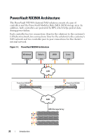
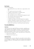
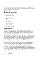
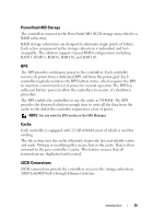
PowerVault MD Storage The controllers connect to the PowerVault MD iSCSI storage array, which is a RAID subsystem. RAID storage subsystems are designed to eliminate single points of failure. Each active component in the storage subsystem is redundant and hotswappable. The solution supports typical RAID configurations including RAID 1, RAID 5, RAID 6, RAID 10, and RAID 50. BPS The BPS provides continuous power to the controllers. Each controller receives its power from a dedicated BPS and from the power grid. Each controller regularly monitors the BPS battery status, which requires the BPS to maintain a minimum level of power for normal operation.The BPS has sufficient battery power to allow the controllers to execute it's shutdown procedure. The BPS enables the controllers to use the cache as NVRAM. The BPS provides the clustered solution enough time to write all the data from the cache to the disk if the controller experiences a loss of power. NOTE: You can view the BPS events on the NAS Manager. Cache Each controller is equipped with 12 GB of RAM, most of which is used for caching. The file system uses the cache efficiently to provide fast and reliable writes and reads. Writing or modifying files occurs first in the cache. Data is then mirrored to the peer controller's cache. This feature ensures that all transactions are duplicated and secured. iSCSI Connections iSCSI connections provide the controllers access to the storage subsystem (MD32x0i/MD36x0i) through Ethernet switches. Introduction 25
-
 1
1 -
2
-
3
-
4
-
5
-
6
-
7
-
8
-
9
-
10
-
11
-
12
-
13
-
14
-
15
-
16
-
17
-
18
-
19
-
 20
20 -
 21
21 -
 22
22 -
 23
23 -
 24
24 -
 25
25 -
 26
26 -
 27
27 -
 28
28 -
 29
29 -
 30
30 -
31
-
32
-
33
-
34
-
35
-
36
-
37
-
38
-
39
-
40
-
41
-
42
-
43
-
44
-
45
-
46
-
47
-
48
-
49
-
50
-
51
-
52
-
53
-
54
-
55
-
56
-
57
-
58
-
59
-
60
-
61
-
62
-
63
-
64
-
65
-
66
-
67
-
68
-
69
-
70
-
71
-
72
-
73
-
74
-
75
-
76
-
77
-
78
-
79
-
80
-
81
-
82
-
83
-
84
-
85
-
86
-
87
-
88
-
89
-
90
-
91
-
92
-
93
-
94
-
95
-
96
-
97
-
98
-
99
-
100
-
101
-
102
-
103
-
104
-
105
-
106
-
107
-
108
-
109
-
110
-
111
-
112
-
113
-
114
-
115
-
116
-
117
-
118
-
119
-
120
-
121
-
122
-
123
-
124
-
125
-
126
-
127
-
128
-
129
-
130
-
131
-
132
-
133
-
134
-
135
-
136
-
137
-
138
-
139
-
140
-
141
-
142
-
143
-
144
-
145
-
146
-
147
-
148
-
149
-
150
-
151
-
152
-
153
-
154
-
155
-
156
-
157
-
158
-
159
-
160
-
161
-
162
-
163
-
164
-
165
-
166
-
167
-
168
-
169
-
170
-
171
-
172
-
173
-
174
-
175
-
176
-
177
-
178
-
179
-
180
-
181
-
182
-
183
-
184
-
185
-
186
-
187
-
188
-
189
-
190
-
191
-
192
-
193
-
194
-
195
-
196
-
197
-
198
 |
 |