Dell PowerVault NX3610 User Manual - Page 15
Storage Arrays, SAN Network, Interconnect Network, LAN Or Client Network
 |
View all Dell PowerVault NX3610 manuals
Add to My Manuals
Save this manual to your list of manuals |
Page 15 highlights
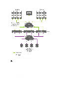
The file system uses the cache efficiently to provide fast and reliable writes and reads. Writing or modifying files occurs first in the cache. Data is then mirrored to the peer controller's cache. This feature ensures that all transactions are duplicated and secured. Each controller is equipped with an internal BPS, which provides continuous power to the controllers for a minimum of five minutes in case of power failure. The controllers regularly monitor the BPS battery status, which requires the BPS to maintain a minimum level of power for normal operation. The BPS has sufficient battery power to allow the controllers to safely shut down. The BPS enables the controllers to use the NVRAM as cache. The BPS provides the clustered solution enough time to write all the data from the cache to the disk if the controller experiences a loss of power. Storage Arrays The controllers connect to a storage array, which is a RAID subsystem. RAID storage subsystems are designed to eliminate single points of failure. Each active component in the storage subsystem is redundant and hot-swappable. The solution supports typical RAID configurations including RAID 1/10, RAID 5, and RAID 6. SAN Network The SAN network is a critical part of the NAS cluster solution. The controller pair resides on the SAN network and communicates to the storage subsystem using the iSCSI protocol for Dell PowerVault NX3500/NX3600/NX3610, or the fibre channel protocol for Dell Compellent FS8600. Interconnect Network The interconnect network is comprised of two independent networks. The interconnect network acts as the heartbeat mechanism and enables internal data transfer between controllers. In a two controller system, no switches are used. In configurations with more than two controllers, the interconnect network includes two switches. All Dell Fluid File System (FluidFS) controllers are connected to both interconnect switches. These employ dual links for redundancy and load balancing. In order to achieve complete data distribution and to maintain high availability, each of the controllers in the Dell FluidFS cluster system must have access to all other controllers in the system. The interconnect network achieves this goal. The interconnect network provides the connectivity for Dell FluidFS clustering, including the heartbeat monitor, transferring data, mirroring information between the controllers' caches and distributing data evenly across all LUNs in the system. LAN Or Client Network After the initial configuration, a virtual IP (VIP) address connects the NAS cluster solution to the client or LAN network. The VIP address allows clients to access the NAS cluster solution as a single entity, thereby providing access to the file system. It enables the NAS cluster solution to perform load balancing between controllers, and ensures that the service continues even if a controller fails. The LAN or client network is comprised of ports on each controller, which connect to the LAN or client network switches. The NAS cluster solution is administered using the LAN or client network on the NAS Management VIP. For routed networks, the number of VIPs that serve the system depends on the number of client ports available to you, for example, a Dell Compellent FS8600 (1 GbE) with four appliances has 32 Client VIPs. For flat networks, only one client VIP is sufficient. 15
-
 1
1 -
2
-
3
-
4
-
5
-
6
-
7
-
8
-
9
-
 10
10 -
 11
11 -
 12
12 -
 13
13 -
 14
14 -
 15
15 -
 16
16 -
 17
17 -
 18
18 -
 19
19 -
 20
20 -
21
-
22
-
23
-
24
-
25
-
26
-
27
-
28
-
29
-
30
-
31
-
32
-
33
-
34
-
35
-
36
-
37
-
38
-
39
-
40
-
41
-
42
-
43
-
44
-
45
-
46
-
47
-
48
-
49
-
50
-
51
-
52
-
53
-
54
-
55
-
56
-
57
-
58
-
59
-
60
-
61
-
62
-
63
-
64
-
65
-
66
-
67
-
68
-
69
-
70
-
71
-
72
-
73
-
74
-
75
-
76
-
77
-
78
-
79
-
80
-
81
-
82
-
83
-
84
-
85
-
86
-
87
-
88
-
89
-
90
-
91
-
92
-
93
-
94
-
95
-
96
-
97
-
98
-
99
-
100
-
101
-
102
-
103
-
104
-
105
-
106
-
107
-
108
-
109
-
110
-
111
-
112
-
113
-
114
-
115
-
116
-
117
 |
 |