Dell Precision T7400 User's Guide - Page 153
Otherwise, continue with step 10.
 |
View all Dell Precision T7400 manuals
Add to My Manuals
Save this manual to your list of manuals |
Page 153 highlights
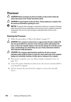
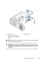
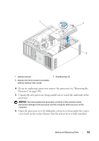
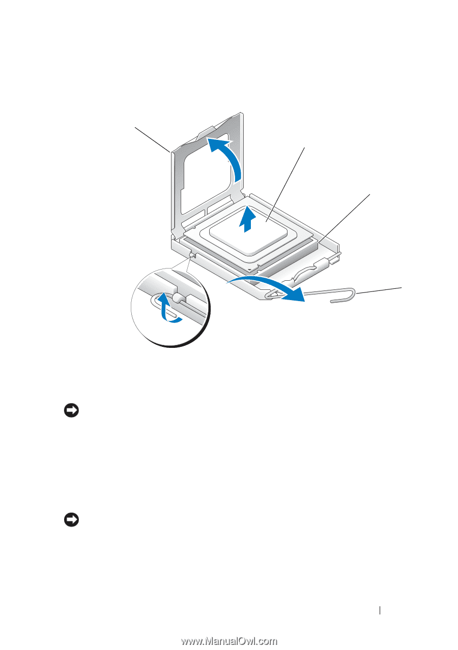
1 2 3 4 1 processor cover 3 socket 2 processor 4 release lever NOTICE: When replacing the processor, do not touch any of the pins inside the socket or allow any objects to fall on the pins in the socket. 8 Gently remove the processor from the socket. 9 If you are installing a new processor, leave the release lever extended in the release position so that the socket is ready for the new processor. See "Installing the Processor" on page 154. Otherwise, continue with step 10. NOTICE: The memory shroud holds the (optional) memory risers in place; its thumbscrews must be sufficiently tight in order to secure the risers and to avoid damage. Adding and Replacing Parts 153
-
 1
1 -
2
-
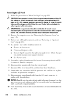
3
-
4
-
5
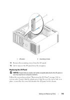
-
6
-
7
-
8
-
9
-
10
-
11
-
12
-
13
-
14
-
15
-
16
-
17
-
18
-
19
-
20
-
21
-
22
-
23
-
24
-
25
-
26
-
27
-
28
-
29
-
30
-
31
-
32
-
33
-
34
-
35
-
36
-
37
-
38
-
39
-
40
-
41
-
42
-
43
-
44
-
45
-
46
-
47
-
48
-
49
-
50
-
51
-
52
-
53
-
54
-
55
-
56
-
57
-
58
-
59
-
60
-
61
-
62
-
63
-
64
-
65
-
66
-
67
-
68
-
69
-
70
-
71
-
72
-
73
-
74
-
75
-
76
-
77
-
78
-
79
-
80
-
81
-
82
-
83
-
84
-
85
-
86
-
87
-
88
-
89
-
90
-
91
-
92
-
93
-
94
-
95
-
96
-
97
-
98
-
99
-
100
-
101
-
102
-
103
-
104
-
105
-
106
-
107
-
108
-
109
-
110
-
111
-
112
-
113
-
114
-
115
-
116
-
117
-
118
-
119
-
120
-
121
-
122
-
123
-
124
-
125
-
126
-
127
-
128
-
129
-
130
-
131
-
132
-
133
-
134
-
135
-
136
-
137
-
138
-
139
-
140
-
141
-
142
-
143
-
144
-
145
-
146
-
147
-
 148
148 -
 149
149 -
 150
150 -
 151
151 -
 152
152 -
 153
153 -
 154
154 -
 155
155 -
 156
156 -
 157
157 -
 158
158 -
159
-
160
-
161
-
162
-
163
-
164
-
165
-
166
-
167
-
168
-
169
-
170
-
171
-
172
-
173
-
174
-
175
-
176
-
177
-
178
-
179
-
180
-
181
-
182
-
183
-
184
-
185
-
186
-
187
-
188
-
189
-
190
-
191
-
192
-
193
-
194
-
195
-
196
-
197
-
198
-
199
-
200
-
201
-
202
-
203
-
204
-
205
-
206
-
207
-
208
-
209
-
210
-
211
-
212
-
213
-
214
-
215
-
216
-
217
-
218
-
219
-
220
-
221
-
222
-
223
-
224
-
225
-
226
-
227
-
228
-
229
-
230
-
231
-
232
-
233
-
234
-
235
-
236
-
237
-
238
-
239
-
240
-
241
-
242
-
243
-
244
-
245
-
246
-
247
-
248
-
249
-
250
-
251
-
252
-
253
-
254
-
255
-
256
-
257
-
258
-
259
-
260
-
261
-
262
-
263
-
264
-
265
-
266
-
267
-
268
-
269
-
270
-
271
-
272
-
273
-
274
-
275
-
276
-
277
-
278
-
279
-
280
-
281
-
282
-
283
-
284
-
285
-
286
-
287
-
288
-
289
-
290
-
291
-
292
-
293
-
294
-
295
-
296
-
297
-
298
-
299
-
300
-
301
-
302
-
303
-
304
-
305
-
306
-
307
 |
 |
Adding and Replacing Parts
153
NOTICE:
When replacing the processor, do not touch any of the pins inside the
socket or allow any objects to fall on the pins in the socket.
8
Gently remove the processor from the socket.
9
If you are installing a new processor, leave the release lever extended in the
release position so that the socket is ready for the new processor. See
"Installing the Processor" on page 154.
Otherwise, continue with step 10.
NOTICE:
The memory shroud holds the (optional) memory risers in place; its
thumbscrews must be sufficiently tight in order to secure the risers and to avoid
damage.
1
processor cover
2
processor
3
socket
4
release lever
1
2
3
4