Dell S5296F-ON EMC PowerSwitch S5200F-ON Series Installation Guide February 20
Dell S5296F-ON Manual
 |
View all Dell S5296F-ON manuals
Add to My Manuals
Save this manual to your list of manuals |
Dell S5296F-ON manual content summary:
- Dell S5296F-ON | EMC PowerSwitch S5200F-ON Series Installation Guide February 20 - Page 1
Dell EMC PowerSwitch S5200F-ON Series Installation Guide February 2022 February 2022 Rev. A07 - Dell S5296F-ON | EMC PowerSwitch S5200F-ON Series Installation Guide February 20 - Page 2
and tells you how to avoid the problem. WARNING: A WARNING indicates a potential for property damage, personal injury, or death. © 2018 - 2022 Dell Inc. or its subsidiaries. All rights reserved. Dell, EMC, and other trademarks are trademarks of Dell Inc. or its subsidiaries. Other trademarks may - Dell S5296F-ON | EMC PowerSwitch S5200F-ON Series Installation Guide February 20 - Page 3
S5200F-ON Series switch configurations...19 Luggage tag...20 Chapter 3: Site preparations...24 Site selection...24 Cabinet placement...24 Rack mounting...25 Switch ground...25 Fans and airflow...25 Power...25 Storing components...26 Chapter 4: S5200F-ON Series switch installation 27 S5232F-ON NEBS - Dell S5296F-ON | EMC PowerSwitch S5200F-ON Series Installation Guide February 20 - Page 4
Management ports...52 RJ45 console port access...52 MicroUSB-B console port access...53 USB storage mount...54 Before you install an OS...54 Check your switch...55 ONIE service 62 Electromagnetic compatibility ...62 Product recycling and disposal...63 Chapter 9: Dell EMC support...64 4 Contents - Dell S5296F-ON | EMC PowerSwitch S5200F-ON Series Installation Guide February 20 - Page 5
Only trained and qualified personnel can install this equipment. Read this guide before you install and power up this equipment. This equipment contains two power cords. Disconnect both power cords before servicing. NOTE: This equipment contains optical transceivers, which comply with the limits of - Dell S5296F-ON | EMC PowerSwitch S5200F-ON Series Installation Guide February 20 - Page 6
NOTE: For the most recent documentation, see Dell EMC support: www.dell.com/support. Information symbols This book uses the following information symbols: NOTE: The Note icon signals Warning icon requires that you take electrostatic precautions when handling the device. 6 About this guide - Dell S5296F-ON | EMC PowerSwitch S5200F-ON Series Installation Guide February 20 - Page 7
(VLT) and stacking-and ports and two 10GbE SFP+ ports ● S5248F-ON: forty-eight 25GbE SFP28 ports, four 100GbE QSFP28 ports, and two 200GbE QSFP-DD ports ● S5296F-ON: ninety-six 25GbE SFP28 ports and eight 100GbE QSFP28 ports The S5232F-ON, S5248F-ON, and S5296F-ON support the following configurations - Dell S5296F-ON | EMC PowerSwitch S5200F-ON Series Installation Guide February 20 - Page 8
12 x 25GbE + 6 x 50GbE The S5232F-ON switch I/O-side view: 1. Stack ID 3. Two 10GbE SFP+ ports The S5248F-ON switch I/O-side view: 2. Thirty-two 100GbE QSFP28 ports 4. LED Status Icons 1. Stack ID 3. Two 200GbE QSFP-DD ports 5. LED status icons The S5296F-ON switch I/O-side view: 2. Forty-eight - Dell S5296F-ON | EMC PowerSwitch S5200F-ON Series Installation Guide February 20 - Page 9
1. Twelve 25GbE SFP28 ports 3. MicroUSB-B console port 5. USB Type A 7. AC PSUs 9. Three 100GbE QSFP28 ports The S5212F-ON DC switch I/O-side view: 2. Stack ID 4. LED status icons 6. RJ45 Ethernet port 8. RJ45 console port 1. Twelve 25GbE SFP28 ports 3. MicroUSB-B console port 2. Stack ID 4. LED - Dell S5296F-ON | EMC PowerSwitch S5200F-ON Series Installation Guide February 20 - Page 10
and DC switches have a reset button on the I/O-side below the Stack ID LED. The S5200F-ON Series switch has one RJ45 serial console port, one Micro-USB type-B console port, one 10/100/1000 Base-T Ethernet management port, one USB type-A port for the external storage, and for the S5212F-ON and S5296F - Dell S5296F-ON | EMC PowerSwitch S5200F-ON Series Installation Guide February 20 - Page 11
100GbE QSFP28 ports and two 10GbE SFP+ ports ○ S5248F-ON-forty-eight 25GbE SFP28 ports, four 100GbE QSFP28 ports, and two 200GbE QSFP-DD ports ○ S5296F-ON-ninety-six 25GbE SFP28 ports and eight 100GbE QSFP28 ports ● One MicroUSB-B console port ● One RJ45 console port ● One USB Type A port for more - Dell S5296F-ON | EMC PowerSwitch S5200F-ON Series Installation Guide February 20 - Page 12
-ON-Standard one rack unit ○ S5232F-ON-Standard one rack unit ○ S5248F-ON-Standard one rack unit ○ S5296F-ON-Standard two rack units Physical section describes open networking installation environment (ONIE) LED behaviors. Some LED behaviors may change after you install your software. LED behavior - Dell S5296F-ON | EMC PowerSwitch S5200F-ON Series Installation Guide February 20 - Page 13
1. Stack ID LED 3. Port Activity LED 5. System LED 7. Fan LED 9. RJ45 Ethernet Port LED The S5248F-ON switch LEDs: 2. Port Activity LEDs 4. Master LED 6. Locator LED 8. Power LED S5200F-ON Series switch 13 - Dell S5296F-ON | EMC PowerSwitch S5200F-ON Series Installation Guide February 20 - Page 14
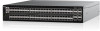
1. Stack ID LED 3. Port Activity LEDs 5. Master LED 7. Locator LED 9. Power LED The S5296F-ON switch LEDs: 2. Port Activity LED 4. Port Activity LEDs 6. System LED 8. Fan LED 10. RJ45 Ethernet Port LED 14 S5200F-ON Series switch - Dell S5296F-ON | EMC PowerSwitch S5200F-ON Series Installation Guide February 20 - Page 15
System LED 7. Fan LED The S5224F-ON switch LEDs: 2. Port Activity LEDs 4. Port Activity LEDs 6. Locator LED 8. Power LED 1. Stack ID LED 3. Port Activity LED 5. System LED 7. Fan LED 9. RJ45 Port LED The S5212F-ON switch LEDs: 2. Port Activity LED 4. Master LED 6. Locator LED 8. Power LED S5200F - Dell S5296F-ON | EMC PowerSwitch S5200F-ON Series Installation Guide February 20 - Page 16
LED FAN LED PSU LED LOCATOR LED/System Beacon 7-Segment LED for stacking 2. Port Activity LED 4. Master LED 6. Locator LED 8. Fan LED Description green-4Hz with five times on and off: Mismatch ● Flashing green-Firmware update ● Off-Locator function disabled ● Flashing blue-Locator function enabled - Dell S5296F-ON | EMC PowerSwitch S5200F-ON Series Installation Guide February 20 - Page 17
, autonegotiated/forced to 1000MBase-T mode ● Solid yellow-Link operating at a lower speed, autonegotiated/forced or 10/100MBase-T mode ● Off-No activity ● Flashing green-Port activity Table 3. SFP28 port LEDs-S5232F-ON, S5248F-ON, and S5296F-ON LED Description Link LED All four LEDs: ● Off - Dell S5296F-ON | EMC PowerSwitch S5200F-ON Series Installation Guide February 20 - Page 18
Table 5. QSFP-DD port LEDs-S5248F-ON (continued) LED Description ● Solid yellow-Port link operating at a lower speed, 100G, 40G or 10G port ● Flashing yellow, ~30ms-Port activity operating at lower speed, 100G, 40G or 10G port ● Flashing yellow, ~1 second on/off-Port beacon Link/Activity LED- - Dell S5296F-ON | EMC PowerSwitch S5200F-ON Series Installation Guide February 20 - Page 19
are required for successful switch installation: NOTE: For detailed installation instructions, see Site preparations and S5200F-ON Series switch installation. ● S5200F-ON Series (S5232F-ON, S5248F-ON, S5296F-ON, S5224F-ON, and S5212F-ON) switch or multiple switches, if stacking ● AC or DC country - Dell S5296F-ON | EMC PowerSwitch S5200F-ON Series Installation Guide February 20 - Page 20
takes you to a How-To site where you can watch videos about racking the switch, replacing components, configuring port channels, and so on. The S5224F-ON, S5232F-ON, or S5248F-ON luggage tag: 1. Service tag 3. PPID The S5296F-ON luggage tag: 20 S5200F-ON Series switch 2. MAC address 4. Express - Dell S5296F-ON | EMC PowerSwitch S5200F-ON Series Installation Guide February 20 - Page 21
1. Service tag 3. PPID The S5212F-ON AC luggage tag: 2. MAC address 4. Express service code S5200F-ON Series switch 21 - Dell S5296F-ON | EMC PowerSwitch S5200F-ON Series Installation Guide February 20 - Page 22
1. MAC address 3. Service tag The S5212F-ON DC luggage tag: 2. Express service code 4. QRL 22 S5200F-ON Series switch - Dell S5296F-ON | EMC PowerSwitch S5200F-ON Series Installation Guide February 20 - Page 23
1. MAC address 3. Service tag 2. Express service code 4. QRL S5200F-ON Series switch 23 - Dell S5296F-ON | EMC PowerSwitch S5200F-ON Series Installation Guide February 20 - Page 24
S5248F-ON, S5296F-ON, S5224F-ON, and S5212F-ON) switch is suitable for installation as part of a common bond network (CBN). You can install Storing components Site selection Install the switch equipment in restricted access areas. A restricted access area is one in which service personnel can only - Dell S5296F-ON | EMC PowerSwitch S5200F-ON Series Installation Guide February 20 - Page 25
service in your area uses. The ground path must be permanent. Switch ground Dell installation is done as part of the factory install based on stock keeping unit (SKU) type. The S5200F-ON Series switch has SKUs that support the following configurations cm) apart. The fan speed varies based on internal - Dell S5296F-ON | EMC PowerSwitch S5200F-ON Series Installation Guide February 20 - Page 26
Storing components If you do not install your S5200F-ON Series switch and components immediately, properly store the switch and all components using these guidelines: ● Storage location temperature must remain constant. The - Dell S5296F-ON | EMC PowerSwitch S5200F-ON Series Installation Guide February 20 - Page 27
S5212F-ON switch installation instructions, see One-half U front-rack installation. For the S5224F-ON, S5248F-ON, and S5232F-ON switches, you can install the ReadyRails system. Due to the chassis weight, the S5296F-ON switch does not support a two-post rack installation; you must install the S5296F - Dell S5296F-ON | EMC PowerSwitch S5200F-ON Series Installation Guide February 20 - Page 28
Dell Technologies recommends changing the front air filter every three months, depending on the switch environment (if applicable). NOTE: If you install interfaces only (Type 4 or 4a ports as described in GR-1089: Electromagnetic reference. Read the safety instructions in your Safety, Environmental, - Dell S5296F-ON | EMC PowerSwitch S5200F-ON Series Installation Guide February 20 - Page 29
the back panel facing downward. One-half U front-rack installation Install the S5212F-ON switch using the following installation instructions. NOTE: To install the S5232F-ON, S5248F-ON, and S5224F-ON switches, see One U ReadyRails installation. To install the S5296F-ON switch, see Two U four-post - Dell S5296F-ON | EMC PowerSwitch S5200F-ON Series Installation Guide February 20 - Page 30
post. 8. Tighten all mounting screws to securely mount the dual tray into the four-post rack. One-half U switch installation Install one or two half-U switches in the four-post rack-mounted dual tray. 1. Install one switch into either dual-tray slot from the front. 30 S5200F-ON Series switch - Dell S5296F-ON | EMC PowerSwitch S5200F-ON Series Installation Guide February 20 - Page 31
the back of the switch. One-half U switch removal Remove the S5212F-ON switch using the following instructions: NOTE: To remove the S5232F-ON, S5248F-ON, S5296F-ON, or S5224F-ON switch, see One U ReadyRails installation. To remove the S5296F-ON switch, see Two U four-post rack assembly. Push in the - Dell S5296F-ON | EMC PowerSwitch S5200F-ON Series Installation Guide February 20 - Page 32
the inside rail out of the outside rail. NOTE: For more installation instructions, see the installation labels attached to the rail assembly. 1U Tool-less mount installation NOTE: For more installation instructions, see the installation labels attached to the rail assembly. 1. Face the ReadyRails - Dell S5296F-ON | EMC PowerSwitch S5200F-ON Series Installation Guide February 20 - Page 33
each rail, pull on the latch release on each flange ear and unseat each rail. Two-post flush-mount installation NOTE: For more installation instructions, see the installation labels attached to the rail assembly. 1. Remove the latch castings from the front side of each ReadyRails assembly, item - Dell S5296F-ON | EMC PowerSwitch S5200F-ON Series Installation Guide February 20 - Page 34
with two user-supplied screws, item 3. 4. Repeat this procedure for the second rail. Two-post center-mount installation NOTE: For more installation instructions, see the installation labels attached to the rail assembly. 1. Slide the plunger bracket rearward until it clicks into place and secure - Dell S5296F-ON | EMC PowerSwitch S5200F-ON Series Installation Guide February 20 - Page 35
with two user-supplied screws, items 2 and 3. 3. Repeat this procedure for the second rail. Four-post threaded installation NOTE: For more installation instructions, see the installation labels attached to the rail assembly. 1. Remove the latch castings from each end of the ReadyRails assemblies. To - Dell S5296F-ON | EMC PowerSwitch S5200F-ON Series Installation Guide February 20 - Page 36
2. For each rail, attach the front and back flanges to the post flanges with two user-supplied screws at each end. Switch installation For the 1U two-post configurations for the S5224F-ON, S5248F-ON, and S5232F-ON switches, slide the switch into the rails in the same manner as the four-post - Dell S5296F-ON | EMC PowerSwitch S5200F-ON Series Installation Guide February 20 - Page 37
feature engages. NOTE: Do not the use the mounted ReadyRails as a shelf or a workplace. 3. Tighten the two thumbscrews and rack screws. S5200F-ON Series switch installation 37 - Dell S5296F-ON | EMC PowerSwitch S5200F-ON Series Installation Guide February 20 - Page 38
install the S5212F-ON switch, see One-half U front-rack installation. To install the S5224F-ON, S5232F-ON, or S5248F-ON, switch see, One U ReadyRail installation. To install in a four-post rack, follow the instructions stabilizing devices, install the stabilizers before mounting or servicing the unit - Dell S5296F-ON | EMC PowerSwitch S5200F-ON Series Installation Guide February 20 - Page 39
DC power connections NOTE: Use the following instructions for all S5200F-ON Series switches except for the S5212F-ON switch. To connect DC power to the S5212F-ON switch, see S5212F-ON only DC power connections. Each DC powered system comes with a set containing a prewired (3-inch 8AWG) power supply - Dell S5296F-ON | EMC PowerSwitch S5200F-ON Series Installation Guide February 20 - Page 40
pins firmly seat and you hear the click of the power connector's left and right levered clamps lock into place. 40 S5200F-ON Series switch installation - Dell S5296F-ON | EMC PowerSwitch S5200F-ON Series Installation Guide February 20 - Page 41
the power connector from the DC PSU socket. S5212F-ON only DC power connections NOTE: Use the following instructions for the S5212F-ON switch only. For all other S5200F-ON Series switches, see DC power connections. power connector from the DC PSU socket. S5200F-ON Series switch installation 41 - Dell S5296F-ON | EMC PowerSwitch S5200F-ON Series Installation Guide February 20 - Page 42
Optics installation The S5200F-ON Series (S5232F-ON, S5248F-ON, S5296F-ON, S5224F-ON, and S5212F-ON) switches have SFP+, SFP28, QSFP-DD, and QSFP28 optical ports. For a list of supported optics, see the specification sheets at www.dell.com/support or contact your Dell EMC Sales representative. - Dell S5296F-ON | EMC PowerSwitch S5200F-ON Series Installation Guide February 20 - Page 43
replacement switch is the same as the previously installed switch. show os-version If the software versions do not match, upgrade the replacement switch software using the procedure included with the firmware download. 10. Copy the backed-up switch configuration to the new switch. copy tftp://hostip - Dell S5296F-ON | EMC PowerSwitch S5200F-ON Series Installation Guide February 20 - Page 44
are field replaceable. When running with full redundancy-two power supplies installed and running-you can remove and replace one PSU without disrupting -frame power supply without integrated fans For the S5224F-ON, S5232F-ON, and S5248F-ON switches, power supply 1 (PSU1) is on the left side of the - Dell S5296F-ON | EMC PowerSwitch S5200F-ON Series Installation Guide February 20 - Page 45
before you insert the PSU in the switch. NOTE: To comply with the GR-1089 Lightning Criteria for Equipment Interfacing with AC or DC Power Ports, use an external surge protection device (SPD) at the AC or DC input of the router. PSU LEDs ● Solid green-Input is OK. ● Flashing yellow - Dell S5296F-ON | EMC PowerSwitch S5200F-ON Series Installation Guide February 20 - Page 46
that you can only fully insert the PSU in one orientation. When you install the PSU correctly, it snaps into place and is flushed with the back the second PSU slot on the S5200F-ON Series switch. S5224F-ON, S5232F-ON, or S5248F-ON switch PSU: ● 1--PSU1 is on the right side of the switch. PSU2 is - Dell S5296F-ON | EMC PowerSwitch S5200F-ON Series Installation Guide February 20 - Page 47
-ON Series switch. NOTE: If a PSU fails, you must replace the entire unit. There are no field serviceable components in the PSU. To request a hardware replacement, see Dell EMC support. NOTE: If you use a single PSU, install a blank plate in the other PSU slot. If you are only using one power supply - Dell S5296F-ON | EMC PowerSwitch S5200F-ON Series Installation Guide February 20 - Page 48
need to twist the power cable clip slightly to get the power cable clip fully inserted into the holes above the power outlet. 3. Repeat the installation procedure with the second power cable clip on the second power outlet. 4. Insert the power cords into the power outlets. 5. Push the power cable - Dell S5296F-ON | EMC PowerSwitch S5200F-ON Series Installation Guide February 20 - Page 49
, you can order and install fan modules separately. The S5200F-ON Series switch supports two airflow direction options. All fans and PSUs in a configuration must be in the same airflow speeds of the fans to accurately determine replacement intervals. Topics: • Components • Fan module installation - Dell S5296F-ON | EMC PowerSwitch S5200F-ON Series Installation Guide February 20 - Page 50
function is normal. ● Flashing yellow-There is a fan fault. ● Off-Fan is off. Fan module installation For all switches except the S5212F-ON, the fan modules in the S5200F-ON Series switch are field replaceable the bay. The S5224F-ON, S5232F-ON, or S5248F-ON switch fan module installation: 50 Fans - Dell S5296F-ON | EMC PowerSwitch S5200F-ON Series Installation Guide February 20 - Page 51
● 1-fan module The S5296F-ON switch fan module installation: ● 1--fan module Fan module replacement To request a hardware replacement, see Dell EMC support. CAUTION: Complete the following steps within one minute or the switch temperature could rise above safe thresholds and the switch could shut - Dell S5296F-ON | EMC PowerSwitch S5200F-ON Series Installation Guide February 20 - Page 52
output may vary. Topics: • RJ45 console port access • MicroUSB-B console port access • USB storage mount • Before you install an OS • Check your switch • ONIE service discovery RJ45 console port access For the S5224F-ON, S5232F-ON, and S5248F-ON switches, the management ports are on the PSU-side of - Dell S5296F-ON | EMC PowerSwitch S5200F-ON Series Installation Guide February 20 - Page 53
cable into the switch console port. 2. Install the DB-9 female-side of the provided copper cable into the serial port on your computer. Or install the DB-9 cable into other data terminal equipment (DTE) server hardware. 3. Use the following settings to make the serial port connection: ● 115200 baud - Dell S5296F-ON | EMC PowerSwitch S5200F-ON Series Installation Guide February 20 - Page 54
flow control USB storage mount USB storage does not automatically mount. USB storage supports the FAT file system. To use USB storage, first mount the device using on /mnt/usb failed: No such device or address. Before you install an OS After powering on the S5200F-ON Series switch, it goes ports - Dell S5296F-ON | EMC PowerSwitch S5200F-ON Series Installation Guide February 20 - Page 55
boots to ONIE Install. ONIE Install boots with ONIE Discovery to the console, ONIE:. NOTE: For more information, see the Open Networking Hardware Diagnostic Guide at www.dell.com/support. NOTE: After you have securely installed and powered on the S5200F-ON Series switch, to configure your switch - Dell S5296F-ON | EMC PowerSwitch S5200F-ON Series Installation Guide February 20 - Page 56
several discovery methods. To download and run an installer, the ONIE Service Discovery feature follows these steps in order and uses the first successful method found: 1. Search locally attached storage devices for one of the ONIE default installer filenames-for example, onie self update from the - Dell S5296F-ON | EMC PowerSwitch S5200F-ON Series Installation Guide February 20 - Page 57
Dispose of the batteries according to the manufacturer's instructions. NOTE: For RoHS information, see Restricted Material Compliance (43.6 mm) S5212F-ON: 1.72 inches (43.6 mm) S5232F-ON: 17.1 inches (434 mm) S5248F-ON: 17.1 inches (434 mm) S5296F-ON: 16.6 inches (422 mm) S5224F-ON: 17.1 inches - Dell S5296F-ON | EMC PowerSwitch S5200F-ON Series Installation Guide February 20 - Page 58
design (continued) Parameter Chassis weight with factory-installed components Rack clearance required Table 8. Environmental 10,000 feet (3,048 meters) 39,370 feet (12,000 meters) Dell EMC Spec SV0115 Specifications S5232F-ON: 100-240 VAC 50/60 Hz S5248F-ON: 100-240 VAC 50/60 Hz S5296F-ON: 100-240 - Dell S5296F-ON | EMC PowerSwitch S5200F-ON Series Installation Guide February 20 - Page 59
-40VDC minimum S5232F-ON: 15.9A @40VDC S5248F-ON: 16.2A @40VDC S5296F-ON: 22 1000BASE-KX) ● 802.3ba (40GbE and 100GbE ports) Agency compliance The S5200F-ON Series switch is designed is not installed and used in accordance to the instructions, it meet FCC emission limits. Dell EMC is not responsible - Dell S5296F-ON | EMC PowerSwitch S5200F-ON Series Installation Guide February 20 - Page 60
a domestic environment, this device may cause radio interference, in which case, you may be required to take adequate measures. European Community Contact Dell EMC, EMEA - Central Dahlienweg 19 66265 Heusweiler Germany Tel: +49 172 6802630 Email: EMEA Central Sales India This product conforms to the - Dell S5296F-ON | EMC PowerSwitch S5200F-ON Series Installation Guide February 20 - Page 61
is used in a domestic environment, radio disturbance may arise. When such trouble occurs, the user may be required to take corrective actions. NOTE: Use the AC power cords with Dell EMC equipment only. Do not use Dell EMC AC power cords with any unauthorized hardware. Figure 4. Japan: warning - Dell S5296F-ON | EMC PowerSwitch S5200F-ON Series Installation Guide February 20 - Page 62
Safety of Laser Products-Part 1: Equipment Classification Requirements and User's Guide ● EN 60825-2 Safety of Laser Products-Part 2: Safety of IEC 60950-1, 2nd Ed, including all National Deviations and Group Differences ● IEC 62368-1 Electromagnetic compatibility Emissions ● International: - Dell S5296F-ON | EMC PowerSwitch S5200F-ON Series Installation Guide February 20 - Page 63
it is no longer needed. Dell EMC offers a variety of product return programs and services in several countries to assist equipment For information on Dell EMC product recycling offerings, see the WEEE Recycling instructions on Support. For more information, contact the Dell EMC Technical Assistance - Dell S5296F-ON | EMC PowerSwitch S5200F-ON Series Installation Guide February 20 - Page 64
. To view the chassis service tag or express service code, pull out the tag or enter the show chassis command from the CLI. ● To receive additional kinds of technical support, click Contact Us, then click Technical Support. To access switch documentation, go to www.dell.com/manuals/ and enter your
-
 1
1 -
 2
2 -
 3
3 -
 4
4 -
 5
5 -
 6
6 -
 7
7 -
8
-
9
-
10
-
11
-
12
-
13
-
14
-
15
-
16
-
17
-
18
-
19
-
20
-
21
-
22
-
23
-
24
-
25
-
26
-
27
-
28
-
29
-
30
-
31
-
32
-
33
-
34
-
35
-
36
-
37
-
38
-
39
-
40
-
41
-
42
-
43
-
44
-
45
-
46
-
47
-
48
-
49
-
50
-
51
-
52
-
53
-
54
-
55
-
56
-
57
-
58
-
59
-
60
-
61
-
62
-
63
-
64
 |
 |

Dell EMC PowerSwitch S5200F-ON Series
Installation Guide
February 2022
February 2022
Rev. A07