Dell S5296F-ON EMC PowerSwitch S5200F-ON Series Setup Guide
Dell S5296F-ON Manual
 |
View all Dell S5296F-ON manuals
Add to My Manuals
Save this manual to your list of manuals |
Dell S5296F-ON manual content summary:
- Dell S5296F-ON | EMC PowerSwitch S5200F-ON Series Setup Guide - Page 1
Dell EMC PowerSwitch S5200F-ON Series Setup Guide - Dell S5296F-ON | EMC PowerSwitch S5200F-ON Series Setup Guide - Page 2
of data and tells you how to avoid the problem. WARNING: A WARNING indicates a potential for property damage, personal injury, or death. © 2019 Dell Inc. or its subsidiaries. All rights reserved. Dell, EMC, and other trademarks are trademarks of Dell Inc. or its subsidiaries. Other trademarks may be - Dell S5296F-ON | EMC PowerSwitch S5200F-ON Series Setup Guide - Page 3
Contents 1 About this guide...4 Related documents...4 Information symbols...5 2 Site preparations...6 Site selection...6 Cabinet placement...6 Rack mounting...6 Switch ground...7 Fans up...22 After switch installation...22 4 Specifications...23 Chassis physical design...23 5 Support...26 Contents 3 - Dell S5296F-ON | EMC PowerSwitch S5200F-ON Series Setup Guide - Page 4
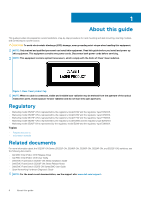
-ON Series (S5232F-ON, S5248F-ON, S5296F-ON, S5224F-ON, and S5212F-ON) switches, see the following documents. • Dell EMC SmartFabric OS10 Release Notes • Dell EMC SmartFabric OS10 User Guide • Delll EMC PowerSwitch S5200F-ON Series Installation Guide • Delll EMC PowerSwitch S5200F-ON Series Release - Dell S5296F-ON | EMC PowerSwitch S5200F-ON Series Setup Guide - Page 5
about hardware handling that could result in injury. NOTE: The ESD Warning icon requires that you take electrostatic precautions when handling the device. About this guide 5 - Dell S5296F-ON | EMC PowerSwitch S5200F-ON Series Setup Guide - Page 6
The 5200F-ON Series (S5232F-ON, S5248F-ON, S5296F-ON, S5224F-ON, and S5212F-ON) switch is suitable for installation as part of Install your equipment in restricted access areas. A restricted access area is one where service personnel can only gain access using a special tool, lock, key, or other - Dell S5296F-ON | EMC PowerSwitch S5200F-ON Series Setup Guide - Page 7
the AC power cable provides a ground path, Dell EMC recommends grounding your switch with a dedicated S5200F-ON Series switch has SKUs that support the following configurations: • AC PSU with fan airflow from service the power supply slots. The switch has multiple power cables. Before servicing - Dell S5296F-ON | EMC PowerSwitch S5200F-ON Series Setup Guide - Page 8
S5232F-ON, S5248F-ON, S5296F-ON, and S5224F-ON: Two hot-swappable PSUs • S5232F-ON, S5248F-ON, S5296F-ON, and S5224F-ON: Four hot-swappable fan units • S5212F clips • S5200F-ON Series Set-up Guide • Safety and Regulatory Information • Warranty and Support Information 1. Place the container on a - Dell S5296F-ON | EMC PowerSwitch S5200F-ON Series Setup Guide - Page 9
of the AC power cable provides a ground path, Dell EMC recommends grounding your switch with a dedicated ground Rack mounting for the S5232F-ON, S5248F-ON, and S5224F-ON switches includes four-post, two-post, round threaded holes This guide is a condensed reference. Read the safety instructions in - Dell S5296F-ON | EMC PowerSwitch S5200F-ON Series Setup Guide - Page 10
facing in the downward position. One-half U front-rack installation Install the S5212F-ON switch using the following installation instructions. NOTE: To install the S5232F-ON, S5248F-ON, or S5224F-ON switch, see One U ReadyRails installation. To install the S5296F-ON switch, see Two U four-post rack - Dell S5296F-ON | EMC PowerSwitch S5200F-ON Series Setup Guide - Page 11
Figure 4. Attach the dual-tray front to the four-post rack front 7. Attach the rear dual-tray switch rails to the four-post rack from the rear. Secure the dual tray to the rack using two user-supplied screws for each rack post. Figure 5. Attach the dual-tray rear to the four-post rack rear 8. - Dell S5296F-ON | EMC PowerSwitch S5200F-ON Series Setup Guide - Page 12
the four-post rack. NOTE: To remove the S5232F-ON, S5248F-ON, or S5224F-ON switch, see One U ReadyRails installation. To remove the S5296F-ON switch, arrow One U ReadyRails installation For the S5248F-ON, S5232F-ON, and S5224F-ON switches, you can install the ReadyRails system using the 1U tool-less - Dell S5296F-ON | EMC PowerSwitch S5200F-ON Series Setup Guide - Page 13
, see the installation labels attached to the rail assembly. Figure 11. Separate rails 1U Tool-less mount installation NOTE: For more installation instructions, see the installation labels attached to the rail assembly. 1. Face the ReadyRails flange ears facing outward. Place one rail between the - Dell S5296F-ON | EMC PowerSwitch S5200F-ON Series Setup Guide - Page 14
on each flange ear and unseat each rail. Two-post flush-mount installation NOTE: For more installation instructions, see the installation labels attached to the rail assembly. 1. For this configuration, remove the latch castings from the front side of each ReadyRails assembly, item 1. To remove the - Dell S5296F-ON | EMC PowerSwitch S5200F-ON Series Setup Guide - Page 15
with two user-supplied screws, items 2 and 3. 3. Repeat this procedure for the second rail. Four-post threaded installation NOTE: For more installation instructions, see the installation labels attached to the rail assembly. 1. Remove the latch castings from each end of the ReadyRails assemblies. To - Dell S5296F-ON | EMC PowerSwitch S5200F-ON Series Setup Guide - Page 16
switch installation For the 1U two-post configurations for the S5248F-ON, S5232F-ON, and S5224F-ON switches, slide the switch into the rails in front-rack installation Configure the rails that are attached to the switch. 1. NOTE: For more information, see the installation instruction labels on - Dell S5296F-ON | EMC PowerSwitch S5200F-ON Series Setup Guide - Page 17
Figure 16. Switch rail attachment 2. After you install both rails, line them up on the ReadyRails. Slide the switch in until it is flush with the front of rack. About three inches before you fully insert your switch, the rail locking feature engages to keep the switch from inadvertently sliding out - Dell S5296F-ON | EMC PowerSwitch S5200F-ON Series Setup Guide - Page 18
the chassis weight, the S5296F-ON switch does not support a two-post rack installation; you must install S5224F-ON switch, see One U ReadyRails installation. To install in a four-post rack, follow the instructions , install the stabilizers before mounting or servicing the unit in the rack. • If - Dell S5296F-ON | EMC PowerSwitch S5200F-ON Series Setup Guide - Page 19
Figure 18. S5296F-ON installation 1. Extra screws to restrict front-back movement of the switch. 2. Main screw DC power connections NOTE: Use the following instructions for all S5200F-ON Series switches except for the S5212F-ON switch. To connect DC power to the S5212F-ON switch, see S5212F-ON only - Dell S5296F-ON | EMC PowerSwitch S5200F-ON Series Setup Guide - Page 20
Figure 19. DC Power Connector and Wiring Block 1. DC wire RTN 3. Captive screws (2) 5. PSU status LED 7. DC wire -48V 2. DC power connector 4. Orange tab 6. DC power socket Figure 20. DC Power Connector Ground 1. Ground nut 3. Lock washer 5. Device grounding rod 2. Washer 4. Ground cable To - Dell S5296F-ON | EMC PowerSwitch S5200F-ON Series Setup Guide - Page 21
's clamps. While continuing to squeeze, pull the power connector from the DC PSU socket. S5212F-ON only DC power connections NOTE: Use the following instructions for the S5212F-ON switch only. For all other S5200F-ON Series switches, see DC power connections. Each DC PSU comes with a connector cable - Dell S5296F-ON | EMC PowerSwitch S5200F-ON Series Setup Guide - Page 22
the release tab, you may need to gently push the optic into the port to ensure that it is seated properly. Do not jerk or tug repeatedly the S5200F-ON Series switch: • If you are using Dell EMC software, see switch documentation at www.dell.com/support. • If you are using third-party software, see - Dell S5296F-ON | EMC PowerSwitch S5200F-ON Series Setup Guide - Page 23
Dispose of the batteries according to the manufacturer's instructions. NOTE: For RoHS information, see Restricted Material ON: 21.4 lbs (9.7 kg)-PSUs and fans S5296F-ON: 33.3 lbs (15.1 kg)-PSUs and fans S5224F-ON: 21.4 lbs (9.7 kg)-PSUs and fans S5212F-ON: 10.05 lbs (4.5 kg)-PSUs and fans Front - Dell S5296F-ON | EMC PowerSwitch S5200F-ON Series Setup Guide - Page 24
Dell EMC Spec SV0115 Specifications S5232F-ON: 100-240 VAC 50/60 Hz S5248F-ON: 100-240 VAC 50/60 Hz S5296F-ON: 100-240 VAC 50/60 Hz S5224F S5248F-ON: 5.8A@110VAC and 2.4A@220VAC S5296F-ON: 8.2A@110VAC and 4.1A@220VAC S5224F-ON: 4.2A@110VAC and 2.1A@220VAC S5212F-ON: 2.8A@110VAC and 1.4A@220VAC S5232F - Dell S5296F-ON | EMC PowerSwitch S5200F-ON Series Setup Guide - Page 25
Table 4. DC power requirements Parameter Minimum and maximum input voltage range Maximum current at full load with fan Specifications -40VDC minimum S5232F-ON: 15.9A @40VDC S5248F-ON: 16.2A @40VDC S5296F-ON: 22.3A @40VDC S5224F-ON: 11.4A@40VDC S5212F-ON: 7.6A@40VDC Specifications 25 - Dell S5296F-ON | EMC PowerSwitch S5200F-ON Series Setup Guide - Page 26
software, and manage your open cases. The support site provides integrated, secure access to these services. To access the support site, go to www.dell.com/support/. To display information in your language, scroll down to the bottom of the web page and select your country from the drop-down
-
 1
1 -
 2
2 -
 3
3 -
 4
4 -
 5
5 -
 6
6 -
 7
7 -
8
-
9
-
10
-
11
-
12
-
13
-
14
-
15
-
16
-
17
-
18
-
19
-
20
-
21
-
22
-
23
-
24
-
25
-
26
 |
 |

Dell EMC PowerSwitch S5200F-ON Series
Setup Guide