Dell Studio 15z Service Manual
Dell Studio 15z Manual
 |
View all Dell Studio 15z manuals
Add to My Manuals
Save this manual to your list of manuals |
Dell Studio 15z manual content summary:
- Dell Studio 15z | Service Manual - Page 1
Dell Studio™ 1555 Service Manual Before You Begin Base Cover Hard Drive Memory Communication Cards Coin-Cell Battery Center Control Cover Keyboard Display Power Button Board Camera (Optional) Palm Rest Speaker Assembly Optical Drive ExpressCard Board AC Adapter Connector USB Connector System Board - Dell Studio 15z | Service Manual - Page 2
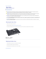
Back to Contents Page Base Cover Dell Studio™ 1555 Service Manual Removing the Base Cover Replacing the Base Cover WARNING: Before working inside your computer, read the safety information that shipped with your computer. For additional safety best practices information, see the Regulatory - Dell Studio 15z | Service Manual - Page 3
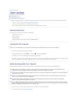
Back to Contents Page Before You Begin Dell Studio™ 1555 Service Manual Recommended Tools Turning Off Your Computer Before Working Inside Your Computer This document provides procedures for removing and installing the components in your computer. Unless otherwise noted, each procedure assumes that: - Dell Studio 15z | Service Manual - Page 4
system board, you must remove the battery from the battery bay before you service the computer. CAUTION: To avoid damage to the computer, use only the battery designed for this particular Dell computer. Do not use batteries designed for other Dell computers. 5. Turn the computer over. 6. Slide the - Dell Studio 15z | Service Manual - Page 5
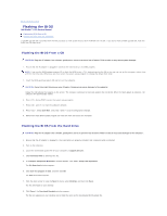
Page Flashing the BIOS Dell Studio™ 1555 Service Manual Flashing the BIOS From a CD Flashing the BIOS From the Hard Drive If a BIOS configuration changes. 6. Remove the flash BIOS-update program CD from the drive and restart the computer. Flashing the BIOS From the Hard Drive CAUTION: Plug the - Dell Studio 15z | Service Manual - Page 6
CAUTION: Do not interrupt this process once it begins. Doing so may cause system damage. 9. Double-click the file icon on the desktop and follow the instructions on the screen. Back to Contents Page - Dell Studio 15z | Service Manual - Page 7
to Contents Page Camera (Optional) Dell Studio™ 1555 Service Manual Removing the Camera Module Replacing the Camera Module WARNING: Before working inside your computer, read the safety information that shipped with your computer. For additional safety best practices information, see the Regulatory - Dell Studio 15z | Service Manual - Page 8
Page Center Control Cover Dell Studio™ 1555 Service Manual Removing the Center Control Cover Replacing the Center Control Cover WARNING: Before working inside your computer, read the safety information that shipped with your computer. For additional safety best practices information, see the - Dell Studio 15z | Service Manual - Page 9
center control cover to the slots on the palm rest and snap the cover in place. 3. Close the display and turn over the computer. 4. In the battery bay, replace the screw that secures the center control cover. 5. Slide the battery into the battery bay until it clicks into place. Back to Contents Page - Dell Studio 15z | Service Manual - Page 10
Back to Contents Page Coin-Cell Battery Dell Studio™ 1555 Service Manual Removing the Coin-Cell Battery Replacing the Coin-Cell Battery WARNING: Before working inside your computer, read the safety information that shipped with your computer. For additional safety best practices information, see the - Dell Studio 15z | Service Manual - Page 11
Back to Contents Page Processor Module Dell Studio™ 1555 Service Manual Removing the Processor Module Replacing the Processor Module WARNING: Before working inside your computer, read the safety information that shipped with your computer. For additional safety best practices information, see the - Dell Studio 15z | Service Manual - Page 12
a new thermal pad along with documentation to illustrate proper installation. 1. Follow the instructions in Before You Begin. 2. Align the pin-1 corner of the processor module with to the system board. 4. Replace the processor heat sink (see Replacing the Processor Heat Sink). Back to Contents Page - Dell Studio 15z | Service Manual - Page 13
Contents Page Processor Heat Sink Dell Studio™ 1555 Service Manual Removing the Processor Heat Sink Replacing the Processor Heat Sink WARNING: Before working inside your computer, read the safety information that shipped with your computer. For additional safety best practices information, see the - Dell Studio 15z | Service Manual - Page 14
removed the processor heat sink and are ready to replace it Replace the system board to the computer base. 3. Replace the six screws that secure the system board to the computer Replacing the ExpressCard Board). 6. Replace the optical drive (see Replacing the Optical Drive). 7. Slide the battery - Dell Studio 15z | Service Manual - Page 15
due to servicing that is not authorized by Dell™ is not covered by your warranty. CAUTION: To help prevent damage to the system board, remove the main battery (see Before Working Inside Your Computer) before working inside the computer. Removing the Display Assembly 1. Follow the instructions in - Dell Studio 15z | Service Manual - Page 16
. 10. Remove the two screws that secure the display assembly to the computer base. 1 camera cable connector 3 power button cable connector 2 display cable connector 4 hinge screws (2) 11. Lift the display assembly out of the computer. Replacing the Display Assembly 1. Follow the instructions in - Dell Studio 15z | Service Manual - Page 17
. 1 display bezel NOTE: In some computers, the display bezel has a double-sided tape on both ends. To avoid damage to the display bezel, remove the display bezel carefully to free it from the double-sided tape. Replacing the Display Bezel 1. Follow the instructions in Before You Begin. 2. Starting - Dell Studio 15z | Service Manual - Page 18
side of the display panel) securing the brackets to the display panel and remove the brackets. 8. Turn over the display panel. 1 display panel bracket (1 2 display cable 3 display cable pull-tab Replacing the Display Panel 1. Follow the instructions in Before You Begin. 2. Connect the display - Dell Studio 15z | Service Manual - Page 19
Replace the display bezel (see Replacing the Display Bezel). 8. Replace the display assembly (see Replacing the Display Assembly). Display Hinges Removing the Display Hinges 1. Follow the instructions in Before You Begin. 2. Remove the display assembly (see Removing the Display Assembly). 3. Remove - Dell Studio 15z | Service Manual - Page 20
Back to Contents Page ExpressCard Board Dell Studio™ 1555 Service Manual Removing the ExpressCard Board Replacing the ExpressCard Board WARNING: Before working inside your computer, read the safety information that shipped with your computer. For additional safety best practices information, see the - Dell Studio 15z | Service Manual - Page 21
Back to Contents Page - Dell Studio 15z | Service Manual - Page 22
Back to Contents Page Fan Dell Studio™ 1555 Service Manual Removing the Fan Replacing the Fan WARNING: Before working inside your computer, read the safety information that shipped with your computer. For additional safety best practices information, see the Regulatory Compliance Homepage at www. - Dell Studio 15z | Service Manual - Page 23
5. Replace the optical drive (see Replacing the Optical Drive). Back to Contents Page - Dell Studio 15z | Service Manual - Page 24
to Contents Page Hard Drive Dell Studio™ 1555 Service Manual Removing the Hard Drive Replacing the Hard Drive WARNING: If you remove the hard drive from the computer when the drive is hot, do not touch the metal housing of the hard drive. WARNING: Before working inside your computer, read the safety - Dell Studio 15z | Service Manual - Page 25
shipped with your computer. Replacing the Hard Drive 1. Follow the instructions in Before You Begin. 2. Replace the hard drive bracket and tighten the four screws to secure the bracket to the hard drive. 3. Place the hard drive assembly in the computer base. 4. Slide in the hard drive assembly to - Dell Studio 15z | Service Manual - Page 26
Back to Contents Page Keyboard Dell Studio™ 1555 Service Manual Removing the Keyboard Replacing the Keyboard WARNING: Before working inside your computer, read the safety information that shipped with your computer. For additional safety best practices information, see the Regulatory Compliance - Dell Studio 15z | Service Manual - Page 27
the tabs along the bottom of the keyboard and slide them into the slots of the palm rest. 5. Press on the corner edges near the top to snap the keyboard into place. 6. Replace the two screws on top of the keyboard. 7. Replace the center control cover (see Replacing the Center Control Cover). Back to - Dell Studio 15z | Service Manual - Page 28
Contents Page Battery Latch Assembly Dell Studio™ 1555 Service Manual Removing the Battery Latch Assembly Replacing the Battery Latch Assembly WARNING: Before working inside your computer, read the safety information that shipped with your computer. For additional safety best practices information - Dell Studio 15z | Service Manual - Page 29
the assembly. 1. Slide the battery latch assembly into place. 2. Replace and tighten the screw securing the battery latch to the battery release latch. 3. Using a small screwdriver, place the spring over the hook on the computer base. 4. Follow the steps in Removing the Battery Latch Assembly in the - Dell Studio 15z | Service Manual - Page 30
Back to Contents Page Memory Dell Studio™ 1555 Service Manual Removing the Memory Module(s) Replacing the Memory Module(s) WARNING: Before working inside your computer, read the safety information that shipped with your computer. For additional safety best practices information, see the Regulatory - Dell Studio 15z | Service Manual - Page 31
2 notch CAUTION: If the base cover is difficult to close, remove the module and reinstall it. Forcing the base cover to close may damage your computer. 3. Replace the base cover (see Replacing the Base Cover). 4. Slide the battery into the battery bay until it clicks into place, or connect the AC - Dell Studio 15z | Service Manual - Page 32
is partially ejected, remove the SIM from the battery bay. Wireless Mini-Cards NOTE: Dell does not guarantee compatibility or provide support for Mini-Cards from sources other than Dell. Your computer supports three Mini-Card slots: l Two full Mini-Card slots - for WWAN, WPAN, UWB, Bluetooth® l One - Dell Studio 15z | Service Manual - Page 33
Internal Card with Bluetooth Wireless Technology - Full Mini-Card NOTE: Your computer can only support two Full Mini-Cards and one Half Mini-Card at a time. NOTE: The WLAN slot supports a half Mini-Card. Removing the Mini-Card 1. Follow the instructions in Before You Begin. 2. Remove the base cover - Dell Studio 15z | Service Manual - Page 34
in the protective mylar sleeve. 8. Replace the base cover (see Replacing the Base Cover). 9. Slide the battery into the bay until it clicks into place. 10. Install the drivers and utilities for your computer, as required. For more information, see the Dell Technology Guide. Back to Contents Page - Dell Studio 15z | Service Manual - Page 35
Back to Contents Page Optical Drive Dell Studio™ 1555 Service Manual Removing the Optical Drive Replacing the Optical Drive WARNING: Before working inside your computer, read the safety information that shipped with your computer. For additional safety best practices information, see the Regulatory - Dell Studio 15z | Service Manual - Page 36
Back to Contents Page Palm Rest Dell Studio™ 1555 Service Manual Removing the Palm Rest Replacing the Palm Rest WARNING: Before working inside your computer, read the safety information that shipped with your computer. For additional safety best practices information, see the Regulatory Compliance - Dell Studio 15z | Service Manual - Page 37
screws (10) 2 power button connector 3 touch pad connector 4 display cable connector 5 camera cable connector 6 speaker connector 9. Carefully lift the palm rest along the rear edge, near the hinge brackets, then gently lift the palm rest to remove it from the computer. Replacing the Palm Rest - Dell Studio 15z | Service Manual - Page 38
to Contents Page Power Button Board Dell Studio™ 1555 Service Manual Removing the Power Button Board Replacing the Power Button Board WARNING: Before working inside your computer, read the safety information that shipped with your computer. For additional safety best practices information, see the - Dell Studio 15z | Service Manual - Page 39
Page AC Adapter Connector Dell Studio™ 1555 Service Manual Removing the AC Adapter Connector Replacing the AC Adapter Connector WARNING: Before working inside your computer, read the safety information that shipped with your computer. For additional safety best practices information, see the - Dell Studio 15z | Service Manual - Page 40
5. Replace the optical drive (see Replacing the Optical Drive). Back to Contents Page - Dell Studio 15z | Service Manual - Page 41
Back to Contents Page Speaker Assembly Dell Studio™ 1555 Service Manual Removing the Speaker Assembly Replacing the Speaker Assembly WARNING: Before working inside your computer, read the safety information that shipped with your computer. For additional safety best practices information, see the - Dell Studio 15z | Service Manual - Page 42
2. Route the speaker cables carefully through the securing tabs on the palm rest. 3. Turn the palm rest over. 4. Replace the screw on the palm rest. 5. Replace the palm rest (see Replacing the Palm Rest). Back to Contents Page - Dell Studio 15z | Service Manual - Page 43
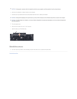
to Contents Page Subwoofer Assembly Dell Studio™ 1555 Service Manual Removing the Subwoofer Assembly Replacing the Subwoofer Assembly WARNING: Before working inside your computer, read the safety information that shipped with your computer. For additional safety best practices information, see the - Dell Studio 15z | Service Manual - Page 44
4. Replace the six screws that secure the system board to the computer base. 5. Connect the AC adapter connector cable, USB cable, fan cable, and the subwoofer cable to their respective connectors on the system board. 6. Replace the optical drive (see Replacing the Optical Drive). Back to Contents - Dell Studio 15z | Service Manual - Page 45
Page System Board Assembly Dell Studio™ 1555 Service Manual Removing the System Board Assembly Replacing the System Board Assembly WARNING: Before working inside your computer, read the safety information that shipped with your computer. For additional safety best practices information, see the - Dell Studio 15z | Service Manual - Page 46
of screws shown here may be greater than the number of screws present on your computer. Replacing the System Board Assembly CAUTION: Ensure that any loose cables do not get caught beneath the system board. Follow the steps in Removing the System Board Assembly in reverse order. Back to Contents Page - Dell Studio 15z | Service Manual - Page 47
Back to Contents Page Dell Studio™ 1555 Service Manual NOTE: A NOTE indicates important information that helps you make better use of your computer. CAUTION: A CAUTION indicates potential damage to hardware or loss of data if instructions are not followed. WARNING: A WARNING indicates a potential - Dell Studio 15z | Service Manual - Page 48
Back to Contents Page USB Connector Dell Studio™ 1555 Service Manual Removing the USB Connector Cable Replacing the USB Connector Cable WARNING: Before working inside your computer, read the safety information that shipped with your computer. For additional safety best practices information, see the - Dell Studio 15z | Service Manual - Page 49
on the computer, replace all screws and ensure that no stray screws remain inside the computer. Failure to do so may result in damage to the computer. 5. Replace the AC adapter connector (see Replacing the AC Adapter Connector). 6. Replace the optical drive (see Replacing the Optical Drive). Back to
-
 1
1 -
 2
2 -
 3
3 -
 4
4 -
 5
5 -
 6
6 -
 7
7 -
8
-
9
-
10
-
11
-
12
-
13
-
14
-
15
-
16
-
17
-
18
-
19
-
20
-
21
-
22
-
23
-
24
-
25
-
26
-
27
-
28
-
29
-
30
-
31
-
32
-
33
-
34
-
35
-
36
-
37
-
38
-
39
-
40
-
41
-
42
-
43
-
44
-
45
-
46
-
47
-
48
-
49
 |
 |

Dell Studio™ 1555 Service Manual
Notes, Cautions, and Warnings
Information in this document is subject to change without notice.
© 2008 Dell Inc. All rights reserved.
Reproduction of these materials in any manner whatsoever without the written permission of Dell Inc. is strictly forbidden.
Trademarks used in this text:
Dell
and the
DELL
logo are trademarks of Dell Inc.;
Bluetooth
is a registered trademark owned by Bluetooth SIG, Inc. and is used by Dell under
license;
Microsoft
,
Windows
,
Windows Vista
, and
Windows Vista start button logo
are either trademarks or registered trademarks of Microsoft Corporation in the United States and/or
other countries.
Other trademarks and trade names may be used in this document to refer to either the entities claiming the marks and names or their products. Dell Inc. disclaims any
proprietary interest in trademarks and trade names other than its own.
Model PP39L
December 2008 Rev. A00
Before You Begin
Base Cover
Hard Drive
Memory
Communication Cards
Coin
-
Cell Battery
Center Control Cover
Keyboard
Display
Power Button Board
Camera (Optional)
Palm Rest
Speaker Assembly
Optical Drive
ExpressCard Board
AC Adapter Connector
USB Connector
System Board Assembly
Processor Heat Sink
Processor Module
Fan
Subwoofer Assembly
Battery Latch Assembly
Flashing the BIOS
NOTE:
A NOTE indicates important information that helps you make better use of your computer.
CAUTION:
A CAUTION indicates potential damage to hardware or loss of data if instructions are not followed.
WARNING:
A WARNING indicates a potential for property damage, personal injury, or death.