Dell Vostro 1710 Service Manual
Dell Vostro 1710 Manual
 |
View all Dell Vostro 1710 manuals
Add to My Manuals
Save this manual to your list of manuals |
Dell Vostro 1710 manual content summary:
- Dell Vostro 1710 | Service Manual - Page 1
Dell™ Vostro™ 1710 Service Manual Troubleshooting Before Working on Your Computer Hard Drive Wireless Local Area Network (WLAN) Card Fan Processor Thermal-Cooling Assembly Processor Module Memory Hinge Cover Keyboard Power Button and Multimedia Button Pads Display Palm Rest Fingerprint Reader - Dell Vostro 1710 | Service Manual - Page 2
Back to Contents Page Before Working on Your Computer Dell™ Vostro™ 1710 Service Manual Recommended Tools What You Need to Know for Your Safety This document provides procedures for removing and installing the components in your computer. Unless otherwise noted, each procedure assumes that: l You - Dell Vostro 1710 | Service Manual - Page 3
to the system board, you must remove the battery from the battery bay before you service the computer. NOTE: To avoid damage to the computer, use only the battery designed for this particular Dell computer. Do not use batteries designed for other Dell computers. 6. Turn the computer upside down - Dell Vostro 1710 | Service Manual - Page 4
1. Ensure that the AC adapter is connected to an electrical outlet, that the main battery is properly installed, and that a network cable is attached. 2. Start the computer. 3. Locate the latest BIOS update file for your computer at support.dell.com. 4. Click Download Now to download the file. 5. If - Dell Vostro 1710 | Service Manual - Page 5
then click Save. The file downloads to your desktop. 8. Click Close if the Download Complete window appears. The file icon appears on your desktop and is titled the same as the downloaded BIOS update file. 9. Double-click the file icon on the desktop and follow the instructions on the screen. Back - Dell Vostro 1710 | Service Manual - Page 6
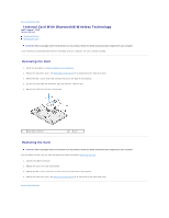
Back to Contents Page Internal Card With Bluetooth® Wireless Technology Dell™ Vostro™ 1710 Service Manual Removing the Card Replacing the Card CAUTION: Before you begin any of the procedures in this section, follow the safety instructions that shipped with your computer. If you ordered a card with - Dell Vostro 1710 | Service Manual - Page 7
Back to Contents Page Coin-Cell Battery Dell™ Vostro™ 1710 Service Manual Removing the Coin-Cell Battery Replacing the Coin-Cell Battery Removing the Coin-Cell Battery CAUTION: Before you begin any of the procedures in this section, follow the safety instructions that shipped with your computer. 1. - Dell Vostro 1710 | Service Manual - Page 8
the Display Assembly). 7. Replace the keyboard (see Replacing the Keyboard). 8. Replace the hinge cover (see Replacing the Hinge Cover). 9. Replace the fan (see Replacing the Fan). 10. Replace the WLAN card (see Replacing a WLAN Card). 11. Replace the hard drive (see Replacing the Hard Drive). Back - Dell Vostro 1710 | Service Manual - Page 9
Back to Contents Page Processor Module Dell™ Vostro™ 1710 Service Manual Removing the Processor Module Replacing the Processor Module Removing the Processor Module CAUTION: Before you begin the following procedure, follow the safety instructions that shipped with your computer. 1. Follow the - Dell Vostro 1710 | Service Manual - Page 10
screw clockwise to secure the processor module to the system board. 3. Replace the processor thermal-cooling assembly (see Replacing the Processor Thermal-Cooling Assembly). 4. Replace the fan (see Replacing the Fan). 5. Replace the memory cover and tighten the eight screws that secure the memory - Dell Vostro 1710 | Service Manual - Page 11
Thermal-Cooling Assembly Dell™ Vostro™ 1710 Service Manual Removing the Processor Thermal-Cooling Assembly Replacing the Processor Thermal-Cooling Assembly Removing the Processor Thermal-Cooling Assembly CAUTION: Before you begin the following procedure, follow the safety instructions that shipped - Dell Vostro 1710 | Service Manual - Page 12
Back to Contents Page USB Daughter Card Dell™ Vostro™ 1710 Service Manual Removing the USB Daughter Card Replacing the USB Daughter Card Removing the USB Daughter Card CAUTION: Before you begin the following procedure, follow the safety instructions that shipped with your computer. 1. Follow the - Dell Vostro 1710 | Service Manual - Page 13
Replacing the Display Assembly). 5. Replace the keyboard (see Replacing the Keyboard). 6. Replace the hinge cover (see Replacing the Hinge Cover). 7. Replace the WLAN card (see Replacing a WLAN Card). 8. Replace the hard drive cover. See Removing the Hard Drive for an illustration of the hard drive - Dell Vostro 1710 | Service Manual - Page 14
Back to Contents Page Display Dell™ Vostro™ 1710 Service Manual Display Assembly Display Bezel Display Panel Display Cable Camera and Microphone Assembly Display Assembly Removing the Display Assembly CAUTION: Before you begin the following procedure, follow the safety instructions that shipped with - Dell Vostro 1710 | Service Manual - Page 15
. 5. Connect the display cable to the display cable connector on the system board. 6. Replace the screw that secures the display cable to the base of the display assembly. 7. In sequential order, replace the four M2.5 x 5-mm screws in the base of the display assembly. 8. Replace the keyboard (see - Dell Vostro 1710 | Service Manual - Page 16
the display bezel. 4. Replace the display assembly (see Replacing the Display Assembly). 5. Replace the keyboard (see Replacing the Keyboard). 6. Replace the hinge cover (see Replacing the Hinge Cover). 7. Reconnect the antenna to the WLAN card (see Replacing a WLAN Card). Display Panel Removing - Dell Vostro 1710 | Service Manual - Page 17
the safety instructions that shipped with your computer. This procedure assumes that you have completed the removal procedure Removing the Display Panel. 1. Replace the eight M2 x 3-mm screws in the display panel. 2. Position the display panel assembly in the top cover. 3. Align the guide pins at - Dell Vostro 1710 | Service Manual - Page 18
cable Replacing the Display Cable CAUTION: Before you begin the following procedure, follow the safety instructions that shipped with your computer. This procedure assumes that you have completed the removal procedure Removing the Display Cable. 1. Connect the display cable to the display inverter - Dell Vostro 1710 | Service Manual - Page 19
7. Replace the display assembly (see Replacing the Display Assembly). 8. Replace the keyboard (see Replacing the Keyboard). 9. Replace the hinge cover (see Replacing the Hinge Cover). 10. Reconnect the antenna to the WLAN card (see Replacing a WLAN Card). Camera and Microphone Assembly Removing the - Dell Vostro 1710 | Service Manual - Page 20
5. Replace the keyboard (see Replacing the Keyboard). 6. Replace the hinge cover (see Replacing the Hinge Cover). 7. Reconnect the antenna to the WLAN card (see Replacing a WLAN Card). Back to Contents Page - Dell Vostro 1710 | Service Manual - Page 21
Back to Contents Page Fan Dell™ Vostro™ 1710 Service Manual Removing the Fan Replacing the Fan Removing the Fan CAUTION: Before you begin the following procedure, follow the safety instructions that shipped with your computer. 1. Follow the instructions in Before Working on Your Computer. 2. Loosen - Dell Vostro 1710 | Service Manual - Page 22
Back to Contents Page Fingerprint Reader Dell™ Vostro™ 1710 Service Manual Removing the Fingerprint Reader Replacing the Fingerprint Reader Removing the Fingerprint Reader CAUTION: Before you begin the following procedure, follow the safety instructions that shipped with your computer. 1. Follow the - Dell Vostro 1710 | Service Manual - Page 23
Replacing the Display Assembly). 6. Replace the keyboard (see Replacing the Keyboard). 7. Replace the hinge cover (see Replacing the Hinge Cover). 8. Replace the WLAN card (see Replacing a WLAN Card). 9. Replace the hard drive cover. See Removing the Hard Drive for an illustration of the hard drive - Dell Vostro 1710 | Service Manual - Page 24
Back to Contents Page Hard Drive Dell™ Vostro™ 1710 Service Manual Removing the Hard Drive Replacing the Hard Drive NOTE: Dell does not guarantee compatibility or provide support for hard drives obtained from sources other than Dell. Removing the Hard Drive CAUTION: Before you begin any of the - Dell Vostro 1710 | Service Manual - Page 25
may find it easier to lift the hard drive starting from the side located opposite from the hard drive's connection to the hard drive cable. Replacing the Hard Drive CAUTION: Before you begin any of the procedures in this section, follow the safety instructions that shipped with your computer. NOTICE - Dell Vostro 1710 | Service Manual - Page 26
Dell™ Vostro™ 1710 Service Manual Removing the Hinge Cover Replacing the Hinge Cover Removing the Hinge Cover CAUTION: Before you begin any of the procedures in this section, follow the safety instructions Turn the computer to the front and open the display all the way (180 degrees). NOTICE: To avoid - Dell Vostro 1710 | Service Manual - Page 27
, follow the safety instructions that shipped with your computer. NOTICE: The hinge cover is fragile and can be damaged if extreme force is used. Exercise care when replacing the hinge cover. This procedure assumes that you have completed the removal procedure Removing the Hinge Cover. 1. Align - Dell Vostro 1710 | Service Manual - Page 28
Back to Contents Page Keyboard Dell™ Vostro™ 1710 Service Manual Removing the Keyboard Replacing the Keyboard Removing the Keyboard CAUTION: Before you begin any of the procedures in this section, follow the safety instructions that shipped with your computer. 1. Follow the procedures in Before - Dell Vostro 1710 | Service Manual - Page 29
This procedure assumes that you have completed the removal procedure Removing the Keyboard. 1. Slide the keyboard cable connector into the keyboard connector on the system board. 2. Rotate the retaining bracket downward to secure the keyboard cable connector. 3. Hook the tabs along the front edge of - Dell Vostro 1710 | Service Manual - Page 30
Back to Contents Page Battery Latch Assembly Dell™ Vostro™ 1710 Service Manual Removing the Battery Latch Assembly Replacing the Battery Latch Assembly Removing the Battery Latch Assembly CAUTION: Before you begin the following procedure, follow the safety instructions that shipped with your - Dell Vostro 1710 | Service Manual - Page 31
Replace the display assembly (see Replacing the Display Assembly). 10. Replace the keyboard (see Replacing the Keyboard). 11. Replace the hinge cover (see Replacing the Hinge Cover). 12. Replace the fan (see Replacing the Fan). 13. Replace the hard drive (see Replacing the Hard Drive). 14. Replace - Dell Vostro 1710 | Service Manual - Page 32
Dell™ Vostro™ 1710 Service Manual Removing a Memory Module Replacing Quick Reference Guide for information on the memory supported by Dell are covered under your computer warranty. Removing a Memory Module CAUTION: Before you begin any of the procedures in this section, follow the safety instructions - Dell Vostro 1710 | Service Manual - Page 33
difficult to close, remove the memory module and reinstall it. Forcing the memory cover to close may damage your computer. 3. Replace the memory cover and tighten the eight screws that secure the memory cover. 4. Insert the battery into the battery bay, or connect the AC adapter to your computer and - Dell Vostro 1710 | Service Manual - Page 34
Wireless Local Area Network (WLAN) Card Dell™ Vostro™ 1710 Service Manual Removing a WLAN Card Replacing a WLAN Card CAUTION: Before you begin any of the procedures in this section, follow the safety instructions that shipped with your computer. Your computer supports a WLAN card. If you ordered - Dell Vostro 1710 | Service Manual - Page 35
If the WLAN card has three triangles on the label (white, black, and gray), connect the white antenna cable to the white triangle, connect the black antenna cable to the black triangle, and connect the gray antenna cable to the gray triangle. 3. Replace the M2 x 3-mm screw that secures the WLAN card - Dell Vostro 1710 | Service Manual - Page 36
Back to Contents Page Optical Drive Dell™ Vostro™ 1710 Service Manual Removing the Optical Drive Replacing the Optical Drive Removing the Optical Drive CAUTION: Before you begin any of the procedures in this section, follow the safety instructions that shipped with your computer. 1. Follow the - Dell Vostro 1710 | Service Manual - Page 37
5. Replace the keyboard (see Replacing the Keyboard). 6. Replace the hinge cover (see Replacing the Hinge Cover). 7. Replace the WLAN card (see Replacing a WLAN Card). 8. Replace the hard drive cover. See Removing the Hard Drive for an illustration of the hard drive cover. Back to Contents Page - Dell Vostro 1710 | Service Manual - Page 38
Vostro™ 1710 Service Manual Removing the Palm Rest Replacing the Palm Rest Removing the Palm Rest CAUTION: Before you begin the following procedure, follow the safety instructions that shipped with your computer. 1. Follow the instructions in Before Working on Your Computer. 2. Remove the hard drive - Dell Vostro 1710 | Service Manual - Page 39
the one M2 x 3-mm screw on the fan to secure the palm rest. 8. Replace the display assembly (see Replacing the Display Assembly). 9. Replace the keyboard (see Replacing the Keyboard). 10. Replace the hinge cover (see Replacing the Hinge Cover). 11. Replace the WLAN card (see Replacing a WLAN Card). - Dell Vostro 1710 | Service Manual - Page 40
12. Replace the hard drive cover. See Removing the Hard Drive for an illustration of the hard drive cover. 13. Replace any blanks you removed from in the ExpressCard slot and the 8- in-1 card slot. Back to Contents Page - Dell Vostro 1710 | Service Manual - Page 41
Pads Dell™ Vostro™ 1710 Service Manual Removing the Power Button and Multimedia Button Pads Replacing the Power Button and Multimedia Button Pads Removing the Power Button and Multimedia Button Pads CAUTION: Before you begin any of the procedures in this section, follow the safety instructions that - Dell Vostro 1710 | Service Manual - Page 42
the M2 x 3-mm screw that secures the multimedia button pad to the palm rest. 7. Connect the multimedia-button pad cable to the connector on the system board. 8. Replace the keyboard (see Replacing the Keyboard). 9. Replace the hinge cover (see Replacing the Hinge Cover). Back to Contents Page - Dell Vostro 1710 | Service Manual - Page 43
Back to Contents Page Speaker Assembly Dell™ Vostro™ 1710 Service Manual Removing the Speaker Assembly Replacing the Speaker Assembly Removing the Speaker Assembly CAUTION: Before you begin the following procedure, follow the safety instructions that shipped with your computer. 1. Follow the - Dell Vostro 1710 | Service Manual - Page 44
6. Replace the hinge cover (see Replacing the Hinge Cover). 7. Replace the WLAN card (see Replacing a WLAN Card). 8. Replace the hard-drive cover. See Removing the Hard Drive for an illustration of the hard drive cover. Back to Contents Page - Dell Vostro 1710 | Service Manual - Page 45
Contents Page System Board Assembly Dell™ Vostro™ 1710 Service Manual Removing the System Board Assembly Replacing the System Board Assembly The system board's BIOS chip contains the Service Tag, which is also visible on a barcode label on the base of the computer. The replacement kit for the system - Dell Vostro 1710 | Service Manual - Page 46
the keyboard (see Replacing the Keyboard). 9. Replace the hinge cover (see Replacing the Hinge Cover). 10. Replace the fan (see Replacing the Fan). 11. Replace the WLAN card (see Replacing a WLAN Card). 12. Replace the hard drive (see Replacing the Hard Drive). 13. Replace any blanks you removed - Dell Vostro 1710 | Service Manual - Page 47
to Contents Page Dell™ Vostro™ 1710 Service Manual Notes, Notices, and Cautions NOTE: A NOTE indicates important information that helps you make better use of your computer. NOTICE: A NOTICE indicates either potential damage to hardware or loss of data and tells you how to avoid the problem. CAUTION - Dell Vostro 1710 | Service Manual - Page 48
Page Troubleshooting Dell™ Vostro™ 1710 Service Manual Troubleshooting Tools Solving Problems Dell Technical Update Service Dell Support Utility Troubleshooting Tools Diagnostic Lights CAUTION: Before you begin any of the procedures in this section, follow the safety instructions that shipped - Dell Vostro 1710 | Service Manual - Page 49
Guide on your computer or at support.dell.com. The Dell Diagnostics is located on a separate diagnostic utility partition on your hard drive. NOTE: If the computer is connected to a docking device (docked), undock it. See the documentation that came with your docking device for instructions - Dell Vostro 1710 | Service Manual - Page 50
follow the instructions on the screen. 10. After all tests have completed, close the test window to return to the Dell Diagnostics Main Menu. 11. Close the Main Menu window to exit the Dell Diagnostics and restart the computer. 12. Remove the Drivers and Utilities media from the optical drive. Dell - Dell Vostro 1710 | Service Manual - Page 51
. Write down the error code and problem description exactly as it appears and follow the instructions on the screen. If you cannot resolve the problem, contact Dell Support. NOTE: When contacting Dell Support, have your Service Tag ready. The Service Tag for your computer is located at the top - Dell Vostro 1710 | Service Manual - Page 52
for installation instructions. drive letter :\ is not accessible. The device is not ready - The drive cannot read the disk. Insert a disk into the drive and try again. Insert bootable media - Insert a bootable floppy disk, CD, or DVD. Non-system disk error - Remove the floppy disk from the - Dell Vostro 1710 | Service Manual - Page 53
about setting power options, see the Dell™ Technology Guide on your computer or at support.dell.com. You can also search for the keyword standby in Windows Help and Support for information on power management modes. Hard drive problems Run Check Disk - Windows XP: 1. Click Start and click My - Dell Vostro 1710 | Service Manual - Page 54
setup - For more information on using the system setup program, see the Dell™ Technology Guide on your computer or at support.dell.com. Ensure that the IEEE 1394 device is recognized by Windows - Windows XP: 1. Click Start and click Control Panel. 2. Under Pick a Category, click Performance and - Dell Vostro 1710 | Service Manual - Page 55
and configured properly. l Verify that the device drivers do not conflict with the program. l If necessary, uninstall and then reinstall the program. Back up your files immediately Use a virus-scanning program to check the hard drive, floppy disks, CDs, or DVDs Save and close any open files or - Dell Vostro 1710 | Service Manual - Page 56
Setup and Quick Reference Guide for your computer at support.dell.com. l Run the Dell Diagnostics (see Dell Diagnostics). Power Problems CAUTION: Before you begin any of the procedures in this section, follow the safety instructions that shipped with your computer. If the power light is green and - Dell Vostro 1710 | Service Manual - Page 57
For information about your graphics card, go to support.dell.com. Check the diagnostic lights - See Diagnostic Lights. Check the display settings - See the Dell™ Technology Guide on your computer or at support.dell.com. Adjust the Windows display settings - Windows XP: 1. Click Start® Control Panel - Dell Vostro 1710 | Service Manual - Page 58
1. Click Start® All Programs® Dell Support® Dell Support Settings. 2. Ensure that the Show icon on the taskbar option is checked. NOTE: If the Dell Support Utility is not available from the Start menu, go to support.dell.com and download the software. The Dell Support Utility is customized for your
-
 1
1 -
 2
2 -
 3
3 -
 4
4 -
 5
5 -
 6
6 -
 7
7 -
8
-
9
-
10
-
11
-
12
-
13
-
14
-
15
-
16
-
17
-
18
-
19
-
20
-
21
-
22
-
23
-
24
-
25
-
26
-
27
-
28
-
29
-
30
-
31
-
32
-
33
-
34
-
35
-
36
-
37
-
38
-
39
-
40
-
41
-
42
-
43
-
44
-
45
-
46
-
47
-
48
-
49
-
50
-
51
-
52
-
53
-
54
-
55
-
56
-
57
-
58
 |
 |

Dell™ Vostro™ 1710
Service Manual
Notes, Notices, and Cautions
If you purchased a DELL™ n Series computer, any references in this document to Microsoft
®
Windows
®
operating systems are not applicable.
Information in this document is subject to change without notice.
© 2008 Dell Inc. All rights reserved.
Reproduction in any manner whatsoever without the written permission of Dell Inc. is strictly forbidden.
Trademarks used in this text:
Dell
, the
DELL
logo, and
Vostro
are trademarks of Dell Inc.;
Microsoft
,
Windows, Windows Vista, and the Windows
start
button logo
are either trademarks
or registered trademarks of Microsoft Corporation in the United States and/or other countries.
Bluetooth
is a registered trademark of Bluetooth SIG Inc.
Other trademarks and trade names may be used in this document to refer to either the entities claiming the marks and names or their products. Dell Inc. disclaims any
proprietary interest in trademarks and trade names other than its own.
September 2009
Rev. A01
Troubleshooting
Before Working on Your Computer
Hard Drive
Wireless Local Area Network (WLAN) Card
Fan
Processor Thermal
-
Cooling
Assembly
Processor Module
Memory
Hinge Cover
Keyboard
Power Button and Multimedia Button Pads
Display
Palm Rest
Fingerprint Reader
Internal Card With Bluetooth Wireless Technology
Optical Drive
System Board Assembly
Speaker Assembly
USB Daughter Card
Battery Latch Assembly
Coin
-
Cell Battery
Flashing the BIOS
NOTE:
A NOTE indicates important information that helps you make better use of your computer.
NOTICE:
A NOTICE indicates either potential damage to hardware or loss of data and tells you how to avoid the problem.
CAUTION:
A CAUTION indicates potential for property damage, personal injury, or death.