Dell i545-2001NBK Service Manual
Dell i545-2001NBK - Inspiron 545 - Desktop PC Manual
 |
UPC - 884116037743
View all Dell i545-2001NBK manuals
Add to My Manuals
Save this manual to your list of manuals |
Dell i545-2001NBK manual content summary:
- Dell i545-2001NBK | Service Manual - Page 1
Dell™ Inspiron™ 535/537/545/546 Service Manual Technical Overview Before You Begin Computer Cover Front Bezel Memory PCI and PCI helps you make better use of your computer. CAUTION: A CAUTION indicates potential damage to hardware or loss of data if instructions are not followed. WARNING: A WARNING - Dell i545-2001NBK | Service Manual - Page 2
Contents Page Before You Begin Dell™ Inspiron™ 535/537/545/546 Service Manual Technical Specifications Recommended Tools Turning Off Your Computer Safety Instructions This chapter provides procedures for removing and installing the components in your computer. Unless otherwise noted, each procedure - Dell i545-2001NBK | Service Manual - Page 3
their electrical outlets. 5. Press and hold the power button while the system is unplugged to ground the system board. CAUTION: Before touching anything inside your computer, ground yourself by touching an unpainted metal surface, such as the metal at the back of the - Dell i545-2001NBK | Service Manual - Page 4
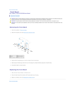
Back to Contents Page Front Bezel Dell™ Inspiron™ 535/537/545/546 Service Manual Removing the Front Bezel Replacing the Front Bezel WARNING: Before working inside your computer, read the safety information that shipped with your computer. For additional safety best practices information, see the - Dell i545-2001NBK | Service Manual - Page 5
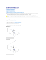
to Contents Page PCI and PCI Express Cards Dell™ Inspiron™ 535/537/545/546 Service Manual Removing the Card Retention Bracket Replacing the Card Retention Bracket Removing PCI and PCI Express Cards Replacing PCI and PCI Express Cards Configuring Your Computer After Removing or Installing a PCI/PCI - Dell i545-2001NBK | Service Manual - Page 6
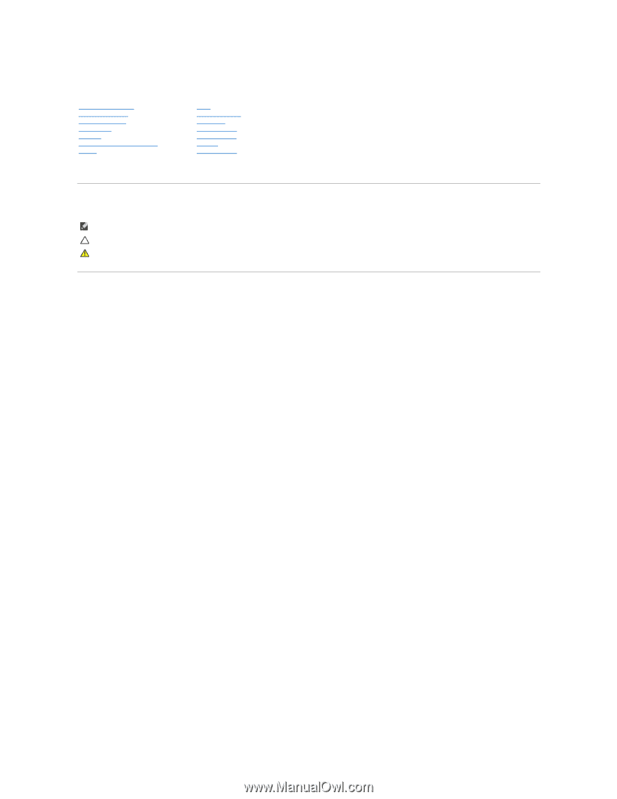
3 alignment bar 4 alignment guide 5 filler bracket 6 guide notch (2) 3. Fix the card retention bracket by replacing the screw. Removing PCI and PCI Express Cards 1. Follow the procedures in Before You Begin. 2. Remove the computer cover (see Removing the Computer Cover). 3. Remove the card - Dell i545-2001NBK | Service Manual - Page 7
the card, making internal connections, or otherwise customizing it for your computer. 5. Place the card in the connector and press down firmly. 1 fully-seated card 2 not fully-seated card 3 alignment bar 4 alignment guide 5 bracket within slot 6 bracket caught outside of slot 6. If you are - Dell i545-2001NBK | Service Manual - Page 8
After Removing or Installing a PCI/PCI Express Card. Configuring Your Computer After Removing or Installing a PCI/PCI Express Card NOTE: For information on location of external connectors, see the Setup Guide. For information on installing drivers and software for your card, see the documentation - Dell i545-2001NBK | Service Manual - Page 9
Dell™ Inspiron™ 535/537/545/546 Service Manual Removing the Battery Replacing the Battery WARNING: Before working inside your computer, read the safety information that shipped with your computer manufacturer's instructions. WARNING: To guard against electrical shock, always unplug your computer from - Dell i545-2001NBK | Service Manual - Page 10
Back to Contents Page - Dell i545-2001NBK | Service Manual - Page 11
Back to Contents Page Computer Cover Dell™ Inspiron™ 535/537/545/546 Service Manual Removing the Computer Cover Replacing the Computer Cover WARNING: Before working inside your computer, read the safety information that shipped with your computer. For additional safety best practices information, - Dell i545-2001NBK | Service Manual - Page 12
1 screws (2) 2 computer cover 3 front of the computer 4 slot 7. Place the computer in an upright position. CAUTION: Ensure that none of the system air-vents are blocked. Blocking them would cause serious thermal problems. Back to Contents Page - Dell i545-2001NBK | Service Manual - Page 13
Back to Contents Page Processor Dell™ Inspiron™ 535/537/545/546 Service Manual Removing the Processor Replacing the Processor WARNING: Before working inside your computer, read the safety information that shipped with your computer. For additional safety best practices information, see the - Dell i545-2001NBK | Service Manual - Page 14
correctly in the socket to avoid permanent damage to the processor and the computer when you turn on the computer. 3. If the release lever on the socket is not fully extended, move it to that position. Inspiron 535/537/545 1 front alignment notch 2 processor pin-1 indicator 3 rear alignment notch - Dell i545-2001NBK | Service Manual - Page 15
9 release lever 1 socket 2 processor pin-1 indicator 3 processor 4 release lever 4. For Inspiron 535/537/545, orient the front and rear alignment-notches on the processor with the front seated and secure. 12. Replace the computer cover (see Replacing the Computer Cover). Back to Contents Page - Dell i545-2001NBK | Service Manual - Page 16
Back to Contents Page Drives Dell™ Inspiron™ 535/537/545/546 Service Manual Removing a Hard Drive Replacing a Hard Drive Removing a Media Card Reader Replacing a Media Card Reader Removing an Optical Drive Replacing an Optical Drive WARNING: Before working inside your computer, read the safety - Dell i545-2001NBK | Service Manual - Page 17
connected and firmly seated. 9. Replace the computer cover (see Replacing the Computer Cover). 10. Connect your computer and devices to electrical outlets, and then turn them on. 11. See the documentation that came with the drive for instructions on installing any software required for drive - Dell i545-2001NBK | Service Manual - Page 18
to electrical outlets, and then turn them on. Removing an Optical Drive 1. Follow the procedures in Before You Begin. 2. Remove the computer cover (see Removing the Computer Cover). 3. Remove the bezel (see Removing the Front Bezel). 4. Disconnect the power cable and the data cable from the back of - Dell i545-2001NBK | Service Manual - Page 19
bezel (see Replacing the Front Bezel). 9. Replace the computer cover (see Replacing the Computer Cover). 10. Connect your computer and devices to their electrical outlets, and turn them on. See the documentation that came with the drive for instructions on installing any software required for drive - Dell i545-2001NBK | Service Manual - Page 20
Back to Contents Page Fans Dell™ Inspiron™ 535/537/545/546 Service Manual Removing the Processor Fan and Heat Sink Assembly Replacing the Processor Fan and Heat Sink Assembly Removing the Chassis Fan Replacing the Chassis Fan WARNING: Before working inside your computer, read the safety information - Dell i545-2001NBK | Service Manual - Page 21
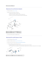
sink assembly NOTE: The processor fan and heat sink assembly in your computer may not look exactly like the one shown in the illustration above. top of the processor. 3. Replace the processor fan and heat sink assembly. Inspiron 535/537/545 a. Align the captive screws on the processor fan and heat - Dell i545-2001NBK | Service Manual - Page 22
connector on the system board (see System Board Components). 4. Remove the screws securing the chassis fan. 5. Slide the chassis fan towards the front of the computer and lift it up. Inspiron™ 535/537 1 screws (2) 2 chassis fan - Dell i545-2001NBK | Service Manual - Page 23
2 chassis fan Replacing the Chassis Fan 1. Follow the procedures in Before You Begin. 2. Slide the chassis fan in place towards the back of the computer. 3. Replace the screws that secure the chassis fan. 4. Connect the chassis fan cable to the chassis fan connector on the system board (see System - Dell i545-2001NBK | Service Manual - Page 24
Back to Contents Page Front I/O Panel Dell™ Inspiron™ 535/537/545/546 Service Manual Removing the Front I/O Panel Replacing the Front I/O Panel WARNING: Before working inside your computer, read the safety information that shipped with your computer. For additional safety best practices information, - Dell i545-2001NBK | Service Manual - Page 25
5. Replace the computer cover (see Replacing the Computer Cover). 6. Connect your computer and devices to an electrical outlet, and turn them on. Back to Contents Page - Dell i545-2001NBK | Service Manual - Page 26
Contents Page Memory Dell™ Inspiron™ 535/537/545/546 Service Manual Removing Memory Replacing Memory Recommended Memory Configuration Setting Up Dual Channel Memory Configuration WARNING: Before working inside your computer, read the safety information that shipped with your computer. For additional - Dell i545-2001NBK | Service Manual - Page 27
has changed, press to continue. 8. Log on to your computer. 9. Right-click the My Computer icon on your Microsoft® Windows® desktop and click Properties. 10. Click the General tab. 11. To verify Memory Configuration NOTE: Dual channel memory is not supported on Inspiron™ 535/537. Inspiron 545 - Dell i545-2001NBK | Service Manual - Page 28
Pair A: matched pair of memory 2 Pair B: matched pair of memory modules in connectors DIMM1 and modules in connectors DIMM2 and DIMM3 DIMM4 Inspiron 546 1 Pair B: matched pair of memory 2 Pair A: matched pair of memory modules in connectors DIMM3 and modules in connectors DIMM1 and DIMM4 - Dell i545-2001NBK | Service Manual - Page 29
Back to Contents Page Power Supply Dell™ Inspiron™ 535/537/545/546 Service Manual Removing the Power Supply Replacing the Power Supply WARNING: Before working inside your computer, read the safety information that shipped with your computer. For additional safety best practices information, see the - Dell i545-2001NBK | Service Manual - Page 30
shock as these screws are a key part of the system grounding. 2. Replace the four screws that secure the power supply to the back of the computer chassis. NOTE: Route the DC power cables under the chassis tabs. The cables must be properly routed to prevent the cables from being damaged. 3. Connect - Dell i545-2001NBK | Service Manual - Page 31
Setup Dell™ Inspiron™ 535/537/545/546 Service Manual Overview Entering System Setup Clearing Forgotten Passwords Clearing CMOS Settings Flashing the BIOS Overview Use System Setup: l To change the system configuration information after you add, change, or remove any hardware in your computer. l To - Dell i545-2001NBK | Service Manual - Page 32
Memory Size 128 MB, 256 MB, MAX (128 MB by default) NOTE: The DVMT Mode and FIXED Memory Size features are not available in Inspiron 537 Integrated Peripherals USB Device Setting l USB Controller-Enabled or Disabled (Enabled by default) l USB Operation Mode-High Speed; Full Speed; Low Speed (High - Dell i545-2001NBK | Service Manual - Page 33
by default) Press Enter to change the user password Inspiron 545 System Info System BIOS Info Service Tag Processor Type Processor L2 Cache Memory Installed Memory Available Memory Speed Memory Channel Mode Memory Technology Displays the computer model number. Shows the BIOS version number and - Dell i545-2001NBK | Service Manual - Page 34
the supervisor password Set User Password User Password Change User Password Inspiron 546 Installed; Not Installed (Not Installed by default) Press Enter Displays the computer model number. Displays the asset tag for the computer, if present. Displays the service tag of the computer. Displays the - Dell i545-2001NBK | Service Manual - Page 35
Management Setup ACPI Suspend Type C1E Support Remote Wake Up AC Recovery Auto Power computer to boot from the CD drive so that you can run the Dell Diagnostics on the Drivers and Utilities media, but you want the computer see the Microsoft Windows desktop. Then shut down your computer and try again. - Dell i545-2001NBK | Service Manual - Page 36
For additional safety best practices information, see the Regulatory Compliance Homepage at www.dell.com/regulatory_compliance. 1. Follow the procedures in Before You Begin. 2. Remove the computer cover (see Removing the Computer Cover). 3. Locate the 3-pin password reset jumper on the system board - Dell i545-2001NBK | Service Manual - Page 37
Inspiron 546 4. Remove the 2-pin jumper plug from pins 2 and 3 and fix it on pins 1 and 2. 5. Turn on the computer, wait for approximately five seconds, and then turn off the computer. If required, press and hold the power button to turn off the computer. 6. Remove the 2-pin jumper plug from pins 1 - Dell i545-2001NBK | Service Manual - Page 38
Inspiron 535/537 Inspiron 545 Inspiron 546 4. Replace the computer cover (see Replacing the Computer Cover). - Dell i545-2001NBK | Service Manual - Page 39
flashing when an update is available or when replacing the system board. 1. Turn on the computer. 2. Locate the BIOS update file for your computer at the Dell Support website at support.dell.com. 3. Click Download Now to download the file. 4. If the Export Compliance Disclaimer window appears - Dell i545-2001NBK | Service Manual - Page 40
Back to Contents Page System Board Dell™ Inspiron™ 535/537/545/546 Service Manual Removing the System Board Replacing the System Board WARNING: Before working inside your computer, read the safety information that shipped with your computer. For additional safety best practices information, see the - Dell i545-2001NBK | Service Manual - Page 41
. CAUTION: Ensure that the port retention springs are not damaged while replacing the sytem board. Inspiron 535/537 1 back of the computer 2 port retention spring Inspiron 545/546 1 back of the computer 2 port retention springs (3) 2. Replace the screws that secure the system board to the chassis - Dell i545-2001NBK | Service Manual - Page 42
you removed them (see Replacing Memory). 7. Replace any add-in cards on the system board (see Replacing PCI and PCI Express Cards). 8. Replace the computer cover (see Replacing the Computer Cover). 9. Connect your computer and devices to an electrical outlet, and turn them on. Back to Contents Page - Dell i545-2001NBK | Service Manual - Page 43
Back to Contents Page Technical Overview Dell™ Inspiron™ 535/537/545/546 Service Manual Inside View of Your Computer System Board Components WARNING: Before working inside your computer, read the safety information that shipped with your computer. For additional safety best practices information, - Dell i545-2001NBK | Service Manual - Page 44
(BATTERY) 18 PCI-Express x1 card slot (PCIEX1) 19 PCI-Express x16 card slot (PCIEX16) 20 chassis fan connector (FAN_SYS) Inspiron 545 1 12 V power connector (PWR2) 2 processor socket 3 processor fan connector (CPU_FAN) 4 memory module connector (DIMM1) 5 memory module connector (DIMM2 - Dell i545-2001NBK | Service Manual - Page 45
1 12 V power connector (PWR2) 2 processor socket 3 processor fan connector (CPU_FAN1) 4 memory module connector (DIMM4) 5 memory module connector (DIMM3) 6 memory module connector (DIMM2) 7 memory module connector (DIMM1) 8 password reset jumper (PSWD1) 9 main power connector (PWR1) 10
-
 1
1 -
 2
2 -
 3
3 -
 4
4 -
 5
5 -
 6
6 -
 7
7 -
8
-
9
-
10
-
11
-
12
-
13
-
14
-
15
-
16
-
17
-
18
-
19
-
20
-
21
-
22
-
23
-
24
-
25
-
26
-
27
-
28
-
29
-
30
-
31
-
32
-
33
-
34
-
35
-
36
-
37
-
38
-
39
-
40
-
41
-
42
-
43
-
44
-
45
 |
 |
Dell™ Inspiron™ 535/537/545/546 Service Manual
Models DCME and DCMF
Notes, Cautions, and Warnings
Information in this document is subject to change without notice.
© 2009 Dell Inc. All rights reserved.
Reproduction of these materials in any manner whatsoever without the written permission of Dell Inc. is strictly forbidden.
Trademarks used in this text:
Dell
, the
DELL
logo, and
Inspiron
are trademarks of Dell Inc.;
Microsoft
and
Windows
are either trademarks or registered trademarks of Microsoft
Corporation in the United States and/or other countries.
Other trademarks and trade names may be used in this document to refer to either the entities claiming the marks and names or their products. Dell Inc. disclaims any
proprietary interest in trademarks and trade names other than its own.
February 2009
Rev. A00
Technical Overview
Before You Begin
Computer Cover
Front Bezel
Memory
PCI and PCI Express Cards
Drives
Fans
Front I/O Panel
Processor
System Board
Power Supply
Battery
System Setup
NOTE:
A NOTE indicates important information that helps you make better use of your computer.
CAUTION:
A CAUTION indicates potential damage to hardware or loss of data if instructions are not followed.
WARNING:
A WARNING indicates a potential for property damage, personal injury, or death.