Denon AVR 1707 Owners Manual - English - Page 7

Display, Front panel - receivers

Page 7 highlights

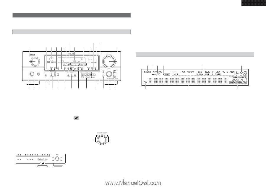
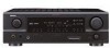
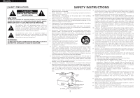
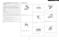
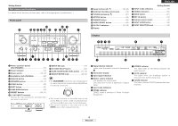
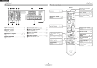
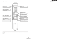
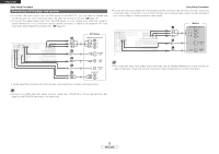
Getting Started Part names and functions For details on the functions of these parts, refer to the pages given in parentheses ( ). Front panel @4 @0 !8 #0 @9 @8 @7 @6 @5 @3 @2 @1 !9 !7 ENGLISH !6 Cursor buttons (D, H 22, 40) !7 MASTER VOLUME control knob 19) !8 TUNING buttons 31) !9 STATUS button 20) @0 DIMMER button 20) @1 VIDEO SELECT button 33) @2 OUTPUT indicators 22, 36) @3 Display Getting Started @4 INPUT mode indicators 19) @5 SIGNAL indicators 22) @6 BAND button 31) @7 EXT. IN button 19) @8 Remote control sensor 3) @9 INPUT MODE button 19) #0 INPUT SELECTOR knob 19) Display oi u y t r t !3 q w e r y u i o !0 !1 !2 !4 !5 !6 q w e q Power operation button (ON/STANDBY 10) w Power indicator 10) e Power switch 10, 37) r Headphones jack (PHONES 20) t ANALOG button 19) y SPEAKER buttons 10, 37) u ZONE2 button 36) i SHIFT button 31) o USER MODE buttons 33) !0 PRESET buttons 30, 31) !1 V. AUX INPUT terminals Remove the cap covering the terminals when you want to use them. !2 SETUP MIC jack 10) !3 SYSTEM SETUP button 40) !4 SURR. MODE/SURR. PARA button····(22, 29) !5 SELECT/ENTER knob 29, 40) • The SELECT/ENTER knob on the main unit operates in the same way as the Cursor buttons (F and G) on the remote control unit. • The control functions in the same way as the Cursor F button when turned counterclockwise, as the Cursor G button when turned clockwise. • The control functions in the same way as the ENTER button when pressed the knob. q Signal channel indicator Lights when the preset channel is displayed at w. w Information display e Input signal indicators r Master volume indicator This displays the volume level. The Setup item number is displayed in System Setup. t Input mode indicators y ZONE2 indicator ZONE2 mode is selected in Power Amplifier Assignment. u STEREO indicator This lights when an FM stereo broadcast has been received. i AUTO indicator This lights when the broadcast station is selected in the AUTO tuning mode. o TUNED indicator This lights when an FM/AM broadcast has been received. 4 ENGLISH

  • 1
  • 2
  • 3
  • 4
  • 5
  • 6
  • 7
  • 8
  • 9
  • 10
  • 11
  • 12
  • 13
  • 14
  • 15
  • 16
  • 17
  • 18
  • 19
  • 20
  • 21
  • 22
  • 23
  • 24
  • 25
  • 26
  • 27
  • 28
  • 29
  • 30
  • 31
  • 32
  • 33
  • 34
  • 35
  • 36
  • 37
  • 38
  • 39
  • 40
  • 41
  • 42
  • 43
  • 44
  • 45
  • 46
  • 47
  • 48
  • 49
  • 50
  • 51
  • 52
  • 53
  • 54
  • 55
  • 56
  • 57
  • 58
  • 59
  • 60
  • 61
  • 62
  • 63
  • 64

Getting Started
Getting Started
4
ENGLISH
ENGLISH
Display
q
Signal channel indicator
Lights when the preset channel is displayed at
w
.
w
Information display
e
Input signal indicators
r
Master volume indicator
This displays the volume level.
The Setup item number is displayed in System
Setup.
t
Input mode indicators
y
ZONE2 indicator
ZONE2 mode is selected in Power Amplifier
Assignment.
u
STEREO indicator
This lights when an FM stereo broadcast has
been received.
i
AUTO indicator
This lights when the broadcast station is
selected in the AUTO tuning mode.
o
TUNED indicator
This lights when an FM/AM broadcast has been
received.
Part names and functions
Front panel
For details on the functions of these parts, refer to the pages given in parentheses (
).
q
Power operation button
(ON/STANDBY)
··········································(10)
w
Power indicator
·········································(10)
e
Power switch
·······································(10, 37)
r
Headphones jack (PHONES)
·····················(20)
t
ANALOG button
········································(19)
y
SPEAKER buttons
································(10, 37)
u
ZONE2 button
············································(36)
i
SHIFT button
··············································(31)
o
USER MODE buttons
································(33)
!
0
PRESET buttons
···································(30, 31)
!
1
V. AUX INPUT terminals
Remove the cap covering the terminals when
you want to use them.
!
2
SETUP MIC jack
·········································(10)
!
3
SYSTEM SETUP button
····························(40)
!
4
SURR. MODE/SURR. PARA button
····(22, 29)
!
5
SELECT/ENTER knob
··························(29, 40)
#
0
@
8
@
6
@
9
@
7
@
3
@
5
@
2
!
9
!
7
@
1
@
0
!
8
@
4
r
y
i
o
!
1
!
4
!
2
!
5
!
6
q
w
t
e
u
!
0
!
3
r
u
y
i
o
w
e
q
t
!
6
Cursor buttons (
D
,
H
)
·························(22, 40)
!
7
MASTER VOLUME control knob
··············(19)
!
8
TUNING buttons (
,
ª
)
·····························(31)
!
9
STATUS button
··········································(20)
@
0
DIMMER button
·········································(20)
@
1
VIDEO SELECT button
······························(33)
@
2
OUTPUT indicators
······························(22, 36)
@
3
Display
@
4
INPUT mode indicators
·····························(19)
@
5
SIGNAL indicators
·····································(22)
@
6
BAND button
··············································(31)
@
7
EXT. IN button
············································(19)
@
8
Remote control sensor
································(3)
@
9
INPUT MODE button
·································(19)
#
0
INPUT SELECTOR knob
····························(19)
• The
SELECT/ENTER
knob on the main unit operates in
the same way as the Cursor buttons (
F
and
G
) on
the remote control unit.
• The control functions in the same way as the
Cursor
F
button when turned counterclockwise,
as the Cursor
G
button when turned clockwise.
• The control functions in the same way as the
ENTER
button when pressed the knob.