Denon AVR-1912 Owners Manual - Page 111

Part names and functions, Front panel - parts

Page 111 highlights

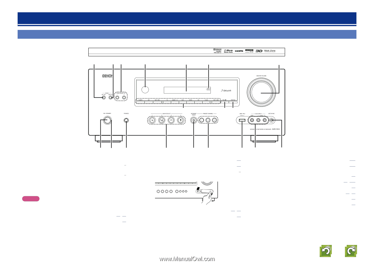
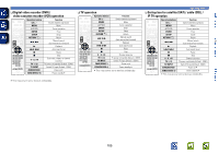
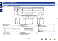
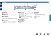
Basic version Part names and functions Front panel For buttons not explained here, see the page indicated in parentheses ( ). Q6 Q5 Q4 Q3 Q2 Q1 Q0 Advanced version Information Q7 Q8 Q9 qw e r ty ui o q Power operation button (ON/STANDBY C 5) Turns power to this unit on and off (standby). w Power indicator C 5) e Headphones jack (PHONES) When the headphones are plugged into this jack, audio will no longer be output from the connected speakers or from the PRE OUT connectors. NOTE To prevent hearing loss, do not raise the volume level excessively when using headphones. r QUICK SELECT buttons 61, 69) t INTERNET RADIO (V) button 29) y PRESET CHANNEL buttons (1 - 3 30) u USB/iPod port 10) i V.AUX INPUT connectors 9) Remove the cap covering the connectors when you want to use them. o SETUP MIC jack 15, 56) Q0 MASTER VOLUME control knob 21) Q1 Master volume indicator Q2 Display 109) Q3 Remote control sensor 112) Q4 Tuner preset channel buttons (TUNER PRESET CH 27) Q5 ZONE SELECT button 68, 101) Q6 ZONE2 ON/OFF button 68) Q7 Input source select buttons 20, 68) Q8 iPod play button (iPod 1 25) Q9 STATUS button 81) 108

  • 1
  • 2
  • 3
  • 4
  • 5
  • 6
  • 7
  • 8
  • 9
  • 10
  • 11
  • 12
  • 13
  • 14
  • 15
  • 16
  • 17
  • 18
  • 19
  • 20
  • 21
  • 22
  • 23
  • 24
  • 25
  • 26
  • 27
  • 28
  • 29
  • 30
  • 31
  • 32
  • 33
  • 34
  • 35
  • 36
  • 37
  • 38
  • 39
  • 40
  • 41
  • 42
  • 43
  • 44
  • 45
  • 46
  • 47
  • 48
  • 49
  • 50
  • 51
  • 52
  • 53
  • 54
  • 55
  • 56
  • 57
  • 58
  • 59
  • 60
  • 61
  • 62
  • 63
  • 64
  • 65
  • 66
  • 67
  • 68
  • 69
  • 70
  • 71
  • 72
  • 73
  • 74
  • 75
  • 76
  • 77
  • 78
  • 79
  • 80
  • 81
  • 82
  • 83
  • 84
  • 85
  • 86
  • 87
  • 88
  • 89
  • 90
  • 91
  • 92
  • 93
  • 94
  • 95
  • 96
  • 97
  • 98
  • 99
  • 100
  • 101
  • 102
  • 103
  • 104
  • 105
  • 106
  • 107
  • 108
  • 109
  • 110
  • 111
  • 112
  • 113
  • 114
  • 115
  • 116
  • 117
  • 118
  • 119
  • 120
  • 121
  • 122
  • 123
  • 124
  • 125
  • 126
  • 127
  • 128
  • 129
  • 130
  • 131
  • 132
  • 133

108
Front panel
For buttons not explained here, see the page indicated in parentheses ( ).
Q
3
Q
4
Q6
Q
5
Q
2
Q
1
Q
0
o
i
Q
7
Q
8
Q
9
u
t
r
y
e
w
q
q
Power operation button
(ON/STANDBY)
································································· (
C
5
)
Turns power to this unit on and off (standby).
w
Power indicator
································································· (
C
5
)
e
Headphones jack (PHONES)
When the headphones are plugged into this jack, audio will no
longer be output from the connected speakers or from the PRE
OUT connectors.
NOTE
To prevent hearing loss, do not raise the volume level excessively
when using headphones.
r
QUICK SELECT buttons
···················································· (
61
,
69
)
t
INTERNET RADIO (
V
) button
··············································· (
29
)
Q
2
Display
···················································································· (
109
)
Q
3
Remote control sensor
························································· (
112
)
Q
4
Tuner preset channel buttons
(TUNER PRESET CH +, –)
························································ (
27
)
Q
5
ZONE SELECT button
····················································· (
68
,
101
)
Q
6
ZONE2 ON/OFF button
··························································· (
68
)
Q
7
Input source select buttons
·············································· (
20
,
68
)
Q
8
iPod play button (iPod
1
)
······················································· (
25
)
Q
9
STATUS button
······································································· (
81
)
y
PRESET CHANNEL buttons (1 – 3)
········································· (
30
)
u
USB/iPod port
········································································· (
10
)
i
V.AUX INPUT connectors
························································· (
9
)
Remove the cap covering the connectors when you want to use
them.
o
SETUP MIC jack
································································· (
15
,
56
)
Q
0
MASTER VOLUME control knob
············································ (
21
)
Q
1
Master volume indicator
Part names and functions