Denon AVR 2807 Owners Manual - English - Page 25
Connecting the MULTI ZONE terminals, Connecting the TRIGGER OUT jacks, Connecting the RS-232C - ipod
 |
UPC - 081757507059
View all Denon AVR 2807 manuals
Add to My Manuals
Save this manual to your list of manuals |
Page 25 highlights
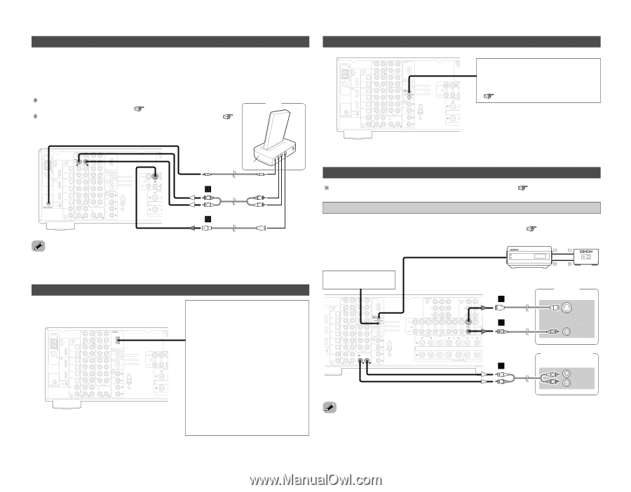
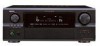
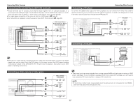
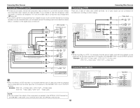
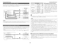
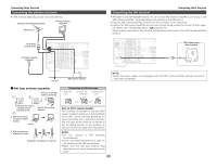
Connecting Other Sources Connecting the iPod® When using an iPod, you must connect the DENON original Control Dock for iPod and the DOCK CONTROL jack on the AVR-2807 with a mini-jack and assign the iPod to any AUDIO and/or SVIDEO terminal(s). The diagram below shows an example of connections for when the iPod is assigned to the VDP terminal. For instructions on assigning the iPod to a specific terminal, see iPod "Setting the iPod Assignment" ( page 47). For instructions on playing the iPod, see "Playing the iPod" ( page 39). Connecting the TRIGGER OUT jacks Connecting Other Sources Turn the DC 12 V voltage on and off for the individual functions and surround modes. For details, see "Setting the Trigger Out" ( page 55). ASD-1R A R R L L AUDIO OUT G S-VIDEO OUT • The optional standard Control Dock for iPod is DENON ASD-1R sold separately. Connecting the RS-232C terminal This is a control expansion terminal for factory use only. Consult you dealer for details. Perform the following operation before using an external controller connected to the RS-232C terminal: 1. Press the ON/STANDBY button on the main unit and set the unit to the operating mode. 2. Perform the operation to turn off the power from the external control. 3. Check that the product has been set to the standby mode. After checking the above, check the connections of the external controller. Operation is possible. Connecting the MULTI ZONE terminals For instructions on operations using the MULTI ZONE functions ( page 40, 41). ZONE2 out connections • If another pre-main (integrated) amplifier is connected, the ZONE2 out (fixed level) terminals can be used to play a different program source in ZONE2 the same time ( page 40). Extension terminal for future use. Input + Output + AUX OUT RC-616 Infrared retransmitter RC-617 Infrared sensor Monitor G (ZONE2) S-VIDEO IN F VIDEO IN Premain amplifier (ZONE2) A L L L IN R R R • For the AUDIO output, use high quality pin-plug cables and wire in such a way that there is no humming or noise. • For instructions on installation and operation of separately sold devices, refer to the devices' operating instructions. 21
-
 1
1 -
2
-
3
-
4
-
5
-
6
-
7
-
8
-
9
-
10
-
11
-
12
-
13
-
14
-
15
-
16
-
17
-
18
-
19
-
 20
20 -
 21
21 -
 22
22 -
 23
23 -
 24
24 -
 25
25 -
 26
26 -
 27
27 -
 28
28 -
 29
29 -
 30
30 -
31
-
32
-
33
-
34
-
35
-
36
-
37
-
38
-
39
-
40
-
41
-
42
-
43
-
44
-
45
-
46
-
47
-
48
-
49
-
50
-
51
-
52
-
53
-
54
-
55
-
56
-
57
-
58
-
59
-
60
-
61
-
62
-
63
-
64
-
65
-
66
-
67
-
68
-
69
-
70
-
71
-
72
-
73
-
74
-
75
-
76
-
77
-
78
-
79
-
80
-
81
-
82
-
83
-
84
-
85
-
86
-
87
-
88
 |
 |