Denon AVR5700 Owners Manual - Page 7
Connecting video components - avr 5700
 |
UPC - 081757503778
View all Denon AVR5700 manuals
Add to My Manuals
Save this manual to your list of manuals |
Page 7 highlights
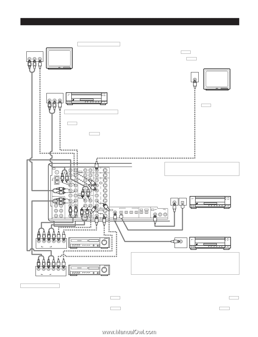
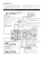
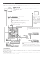
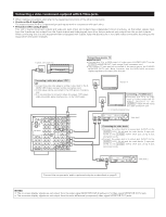
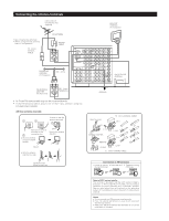
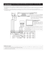
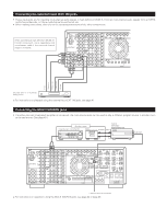
Connecting video components • To connect the video signal, connect using a 75 Ω/ohms video signal cable cord. Using an improper cable can result in a drop in sound quality. • When making connections, also refer to the operating instructions of the other components. TV or DBS tuner AUDIO VIDEO OUT R L OUT RL Connecting a TV/DBS tuner TV/DBS • Connect the TV's or DBS tuner's video output jack (VIDEO OUTPUT) to the VIDEO (yellow) TV/DBS IN jack using a 75 Ω/ohms video coaxial pin plug cord. • Connect the TV's or DBS tuner's audio output jacks (AUDIO OUTPUT) to the AUDIO TV/DBS IN jacks using pin plug cords. Monitor TV VIDEO IN AUDIO VIDEO OUT R L OUT LD player, CDV player, etc. RL Connecting a video disc player VDP VDP • Connect the video disc player's video output jack (VIDEO OUTPUT) to the VIDEO (yellow) VDP/DVD IN jack using a 75 Ω/ohms video coaxial pin plug cord. • Connect the video disc player's analog audio output jacks (ANALOG AUDIO OUTPUT) to the AUDIO VDP/DVD IN jacks using pin plug cords. • A DVD player can be connected to the DVD jacks in the same way. • It is also possible to connect a video disc player, DVD player, video camcorder, game machine, etc., to the V.AUX jacks. MONITOR OUT • Connect the TV's video input jack (VIDEO INPUT) to the VIDEO MONITOR OUT jack using a 75 Ω/ohms video coaxial pin plug cord. • The monitor TV can also be connected in the same way to the VIDEO MONITOR OUT-2 jack. Note, however, that the AVR-5700's onscreen display signals are not output from this jack. (See page 26.) IN AM FM PHONO COAX. 75 R SIGNAL CD GND RL LOOP ANT. DVD VDP ANTENNA TERMIRNALS TV/ DBS L V.AUX 6CH EXT. IN R FR FL VCR-1 L SW C VCR-2 SR SL MD/ R TAPE-1 ER EL TAPE-2 8CH EXT. IN MULTI SOURCE OUT L FRONT CENTER SUB WOOFER SURROUND EFECT PREORUT R L L OUT R L VCR-1 VCR-2 L MD/ TAPRE-1 L TAPE-2 AUDIO MONITOR OUT-1 MONITOR OUT-2 DVD IN VDP TV / DBS V.AUX VCR-1 VCR-2 OUT VCR-1 DOLBY DIGITAL IN RF 1 VCR-2 VIDEO S-VIDEO OPTICAL 2 3 OPTICAL-5 4 IN OUT DIGITAL Note on connecting the digital input jacks • Only audio signals are input to the digital input jacks. For details, see page 6. OUTPUT COAXIAL OPTICAL LD player or other component equipped with digital output jacks IN COAXIAL 1 2 3 R LRL Video deck 2 R L R L OUT IN OUT IN AUDIO VIDEO R LR L Video deck 1 R L R L OUT IN OUT IN AUDIO VIDEO LD player or other component equipped with a Dolby Digital RF output jack AC-3RF OUT NOTES: Video output connections for LD players equipped with AC-3RF output jacks. • To connect an Dolby Digital AC-3 compatible LD player to the AC-3RF jacks, connect the player's video outputs to this unit's VDP/DVD input jacks. • When the AC-3RF-input selector button on the AVR-5700 is pressed, the picture switches to the signals input to the VDP/DVD input jacks. Connecting a video decks • There are two sets of video deck (VCR) jacks, so two video decks can be connected for simultaneous recording or video copying. Video input/output connections: • Connect the video deck's video output jack (VIDEO OUT) to the VIDEO (yellow) VCR-1 IN jack, and the video deck's video input jack (VIDEO IN) to the VIDEO (yellow) VCR-1 OUT jack using 75 Ω/ohms video coaxial pin plug cords. Connecting the audio output jacks • Connect the video deck's audio output jacks (AUDIO OUT) to the AUDIO VCR-1 IN jacks, and the video deck's audio input jacks (AUDIO IN) to the AUDIO VCR-1 OUT jacks using pin plug cords. 2 Connect the second video deck to the VCR-2 jacks in the same way. 7
-
 1
1 -
 2
2 -
 3
3 -
 4
4 -
 5
5 -
 6
6 -
 7
7 -
 8
8 -
 9
9 -
 10
10 -
 11
11 -
 12
12 -
13
-
14
-
15
-
16
-
17
-
18
-
19
-
20
-
21
-
22
-
23
-
24
-
25
-
26
-
27
-
28
-
29
-
30
-
31
-
32
-
33
-
34
-
35
-
36
-
37
-
38
-
39
-
40
-
41
-
42
-
43
-
44
-
45
-
46
-
47
-
48
-
49
-
50
-
51
-
52
-
53
-
54
-
55
-
56
-
57
-
58
-
59
-
60
-
61
-
62
-
63
-
64
 |
 |