Denon DRA 395 Owners Manual - Page 10

PART NAMES AND FUNCTIONS, Protector circuit, Note on speaker impedance - stereo receiver

Page 10 highlights

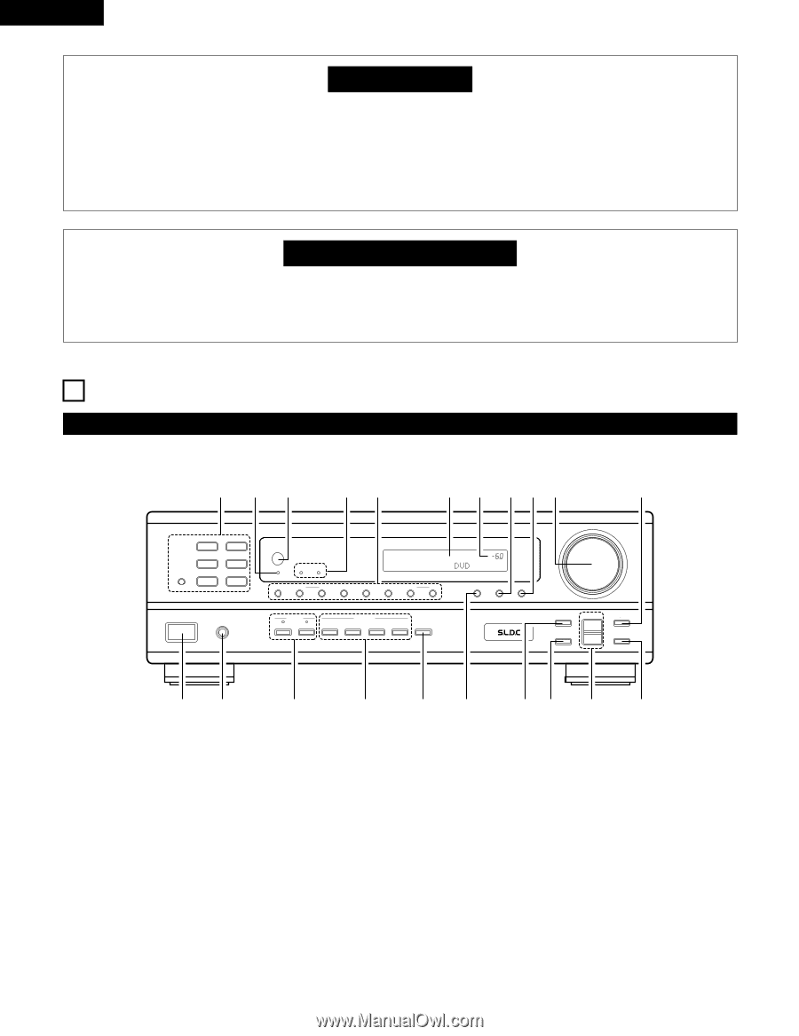
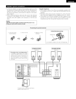
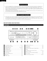
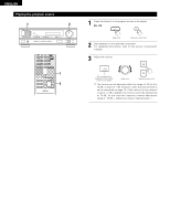
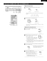
ENGLISH Protector circuit • This unit is equipped with a high-speed protection circuit. This circuit protects the internal circuitry from damage due to large currents flowing if the speaker jacks are not completely connected or if an output is generated by a short circuit. In such a case, the protection circuit will operate to cut off the output to the speakers. Should this happen, turn the power off and check the speaker connections. Then turn the power on again. After muting for several seconds, the receiver should be operating normally. If the protection circuit is activated again even though there are no problems with the wiring or the ventilation around the unit, switch off the power and contact a DENON service center. Note on speaker impedance • The protector circuit may be activated if the set is played for long periods of time at high volumes when speakers with an impedance lower than the specified impedance (for example speakers with an impedance of lower than 4 Ω/ohms) are connected. If the protector circuit is activated, the speaker output is cut off. Turn off the set's power, wait for the set to cool down, improve the ventilation around the set, then turn the power back on. 6 PART NAMES AND FUNCTIONS Front Panel • For details on the functions of these parts, refer to the pages given in parentheses ( ). @1 @0 !9 !8 !7 !6 !5 !4 !38 !2 !1 B PRECISION AUDIO COMPONENT / STEREO RECEIVER DRA-395 CD PHONO TUNER CDR / TAPE VCR DVD / VDP V.AUX REMOTE SENSOR ON / STANDBY Multi Room Music Entertainment System ZONE 2 ZONE 3 SHIFT DOWN UP PRESET BAND MODE MEMORY DOWN UP TUNING ON / STANDBY PHONES SPEAKER A B REC OUT REC / MULTI ZONE 2 ZONE 3 SELECT LOUDNESS VOLUME LEVEL MASTER VOLUME VIDEO SELECT DIMMER STATUS TONE DEFEAT CH VOL SELECT UP DOWN TREBLE BASS qw e r t y u i o !0 q Power operation switch 13, 21) w Headphone jacks (PHONES 19) e SPEAKER A/B buttons 13, 19, 24) r REC/MULTI buttons 17, 18) t LOUDNESS button 15) y VIDEO SELECT button 19) u TONE DEFEAT button 15) i CH VOL button 15) o SELECT UP/DOWN buttons 15) !0 BASS button 15) !1 TREBLE button 15) !2 MASTER VOLUME control 14) !3 STATUS button 20) !4 DIMMER button 20) !5 MASTER VOLUME indicator (VOLUME LEVEL 14) !6 Display !7 Tuning/Preset memory selector buttons 21ʙ 23) !8 ZONE 2, 3 indicator 18) !9 Remote control sensor (REMOTE SENSOR 11) @0 Power indicator 13) @1 Input source selector buttons 14, 22) 10

  • 1
  • 2
  • 3
  • 4
  • 5
  • 6
  • 7
  • 8
  • 9
  • 10
  • 11
  • 12
  • 13
  • 14
  • 15
  • 16
  • 17
  • 18
  • 19
  • 20
  • 21
  • 22
  • 23
  • 24
  • 25
  • 26
  • 27
  • 28
  • 29
  • 30
  • 31
  • 32
  • 33
  • 34
  • 35
  • 36
  • 37
  • 38
  • 39
  • 40
  • 41
  • 42
  • 43
  • 44
  • 45
  • 46
  • 47
  • 48
  • 49
  • 50

10
ENGLISH
Protector circuit
This unit is equipped with a high-speed protection circuit. This circuit protects the internal circuitry from damage due to
large currents flowing if the speaker jacks are not completely connected or if an output is generated by a short circuit.
In such a case, the protection circuit will operate to cut off the output to the speakers. Should this happen, turn the
power off and check the speaker connections. Then turn the power on again. After muting for several seconds, the
receiver should be operating normally.
If the protection circuit is activated again even though there are no problems with the wiring or the ventilation around
the unit, switch off the power and contact a DENON service center.
Note on speaker impedance
The protector circuit may be activated if the set is played for long periods of time at high volumes when speakers with
an impedance lower than the specified impedance (for example speakers with an impedance of lower than 4
/ohms)
are connected. If the protector circuit is activated, the speaker output is cut off. Turn off the set
s power, wait for the set
to cool down, improve the ventilation around the set, then turn the power back on.
6
PART NAMES AND FUNCTIONS
Front Panel
For details on the functions of these parts, refer to the pages given in parentheses (
).
VOLUME LEVEL
B
DRA-395
PRECISION AUDIO COMPONENT / STEREO RECEIVER
PHONES
ON / STANDBY
SPEAKER
A
B
TONE
DEFEAT
TREBLE
SELECT
UP
TUNING
MODE
BAND
MEMORY
VIDEO SELECT
DIMMER
STATUS
SHIFT
DOWN
UP
PRESET
DOWN
MASTER VOLUME
UP
DOWN
PHONO
DVD / VDP
VCR
CD
TUNER
V.AUX
ON / STANDBY
REMOTE
SENSOR
ZONE 2
REC OUT
ZONE 3
SELECT
LOUDNESS
BASS
CH VOL
CDR / TAPE
Music Entertainment System
M
ulti Room
ZONE 2
ZONE 3
REC / MULTI
q
w
r
e
!
4
!
5
!
6
!
7
!
9
!
8
@
0
y
i
u
o
!
0
t
!
1
!
3
8!
2
@
1
q
Power operation switch
....................................................
(13, 21)
w
Headphone jacks (PHONES)
...................................................
(19)
e
SPEAKER A/B buttons
................................................
(13, 19, 24)
r
REC/MULTI buttons
..........................................................
(17, 18)
t
LOUDNESS button
..................................................................
(15)
y
VIDEO SELECT button
............................................................
(19)
u
TONE DEFEAT button
.............................................................
(15)
i
CH VOL button
........................................................................
(15)
o
SELECT UP/DOWN buttons
....................................................
(15)
!
0
BASS button
............................................................................
(15)
!
1
TREBLE
button
.......................................................................
(15)
!
2
MASTER VOLUME control
.....................................................
(14)
!
3
STATUS button
.......................................................................
(20)
!
4
DIMMER button
......................................................................
(20)
!
5
MASTER VOLUME indicator (VOLUME LEVEL)
.....................
(14)
!
6
Display
!
7
Tuning/Preset memory selector buttons
........................
(21
23)
!
8
ZONE 2, 3 indicator
.................................................................
(18)
!
9
Remote control sensor (REMOTE SENSOR)
..........................
(11)
@
0
Power indicator
.......................................................................
(13)
@
1
Input source selector buttons
...........................................
(14, 22)