Denon DRA 395 Owners Manual - Page 6
CONNECTIONS, Connecting the audio components - remote control
 |
UPC - 081757504614
View all Denon DRA 395 manuals
Add to My Manuals
Save this manual to your list of manuals |
Page 6 highlights
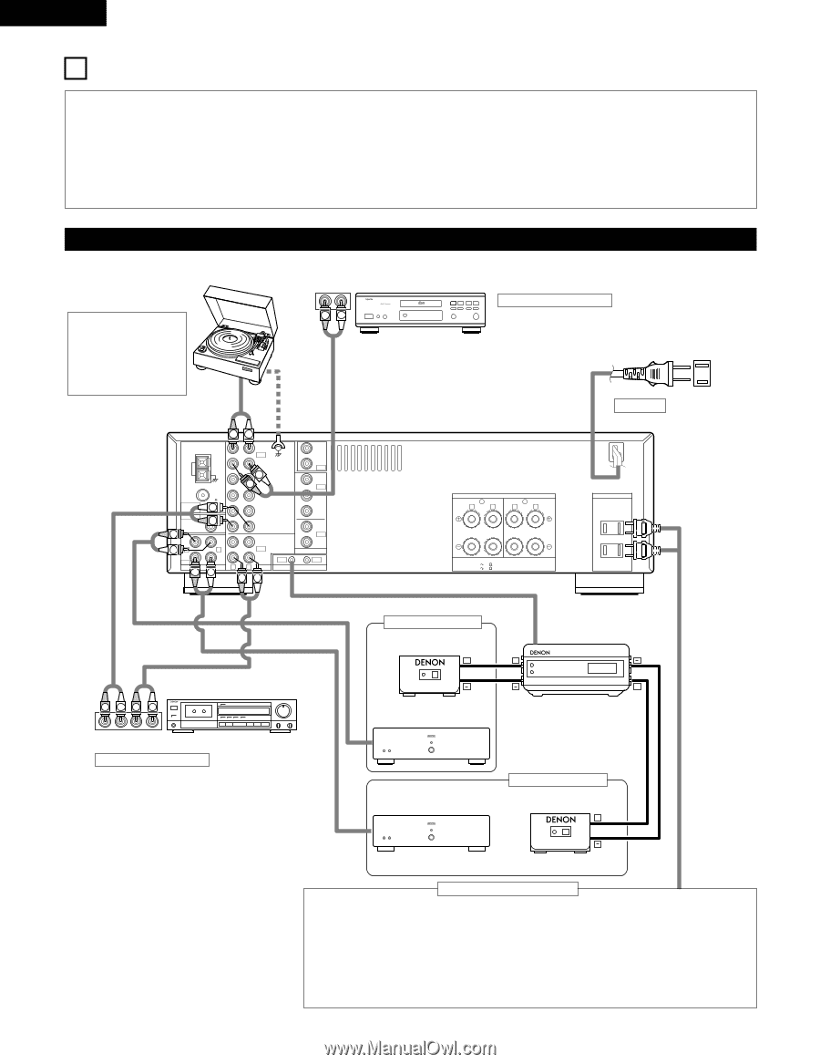
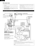
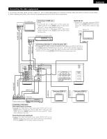
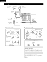
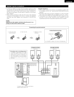
ENGLISH 5 CONNECTIONS • Do not plug in the power cord until all connections have been completed. • Be sure to connect the left and right channels properly (left with left, right with right). • Insert the plugs securely. Incomplete connections will result in the generation of noise. • Use the AC OUTLETS for audio equipment only. Do not use them for hair driers, etc. • Note that binding pin plug cords together with power cords or placing them near a power transformer will result in generating hum or other noise. • If hum or other noise is produced when the ground wire is connected, disconnect it. • Noise or humming may be generated if a connected component is used independently without turning the power of this unit on. If this happens, turn on the power of the this unit. Connecting the audio components Turntable (MM cartridge) NOTE: This unit cannot be used with MC cartridges directly. Use a separate head amplifier or stepup transformer. OUTPUT CD player RL RL DIGITAL AUDIO LINE OUT Ground wire RL LOOP ANT. AM FM COAX. 75 PHONO IN CD SIGNAL GND L DVD/ VDP R V. AUX ZONE 2 MULTI ROOM ZONE 3 OUT DVD/ VDP IN V. AUX ANTENNA TERMINALS L VCR VCR PRE OUT SUB R CDR/ WOOFER TAPE MONITOR R OUT ZONE 2 VCR VCR LR L OUT ZONE CDR/ VIDEO OUT 3 TAPE IN OUT MULTI ROOM R L AUDIO ROOM TO ROOM (REMOTE CONTROL) RL RL Connecting a CD player Connect the CD player's analog output jacks (ANALOG OUTPUT) to this unit's CD jacks using pin plug cords. AC CORD AC 120 V, 60 Hz SPEAKER SYSTEMS B A R L R L SPEAKER IMPEDANCE A OR B / 4 16 A + B / 8 16 AUX OUT AC OUTLETS AC 120V 60Hz SWITCHED TOTAL 120W(1A.) MAX. LINE OUT INPUT LINE IN Sub room (ZONE 2) RC-617 (Sold Separately) Infrared sensor + RC-616 (Sold Separately) Infrared retransmitter + Tape deck R LR L R LR L OUTPUT INPUT Connecting a tape deck Connections for recording: Connect the tape deck's recording input jacks (LINE IN or REC) to this unit's tape recording (OUT) jacks using pin plug cords. Connections for playback: Connect the tape deck's playback output jacks (LINE OUT or PB) to this unit's tape playback (IN) jacks using pin plug cords. OUTPUT INPUT Power amplifier + INPUT Power amplifier Sub room (ZONE 3) RC-617 (Sold Separately) Infrared sensor + OUTPUT Connecting the AC OUTLETS AC OUTLETS • SWITCHED (total capacity - 120 W (1 A.) The power to this outlet is turned on and off in conjunction with the POWER operation switch on the main unit, and when the power is switched between on and standby from the remote control unit. No power is supplied from these outlets when this unit's power is at standby. Never connect equipment whose total capacity is above 120 W (1 A.) NOTE: Use the AC OUTLETS for audio equipment only. Do not use them for hair driers, etc. 6
-
 1
1 -
 2
2 -
 3
3 -
 4
4 -
 5
5 -
 6
6 -
 7
7 -
 8
8 -
 9
9 -
 10
10 -
 11
11 -
 12
12 -
13
-
14
-
15
-
16
-
17
-
18
-
19
-
20
-
21
-
22
-
23
-
24
-
25
-
26
-
27
-
28
-
29
-
30
-
31
-
32
-
33
-
34
-
35
-
36
-
37
-
38
-
39
-
40
-
41
-
42
-
43
-
44
-
45
-
46
-
47
-
48
-
49
-
50
 |
 |