Dewalt D26451K Instruction Manual
Dewalt D26451K Manual
 |
View all Dewalt D26451K manuals
Add to My Manuals
Save this manual to your list of manuals |
Dewalt D26451K manual content summary:
- Dewalt D26451K | Instruction Manual - Page 1
revolutions per minute COMPONENTS (Fig. 1) A. On/Off switch B. Speed control dial (D26453) C. Sanding pad D. Dust collection bag E. Vac-adapter F. CFS disc (Fig. 6) Motor Your DEWALT tool is powered by a DEWALT built motor. Be sure your power supply agrees with the nameplate marking. (Volts, 120 - Dewalt D26451K | Instruction Manual - Page 2
it after every 5 hours of use. 2. As part of CFS (Controlled Finishing System®), your sander is equipped with a replaceable disc (F) which is located between the pad (C) and the sander body (G). It is designed to increase the dust collection efficiency and control the pad speed while the unit is off - Dewalt D26451K | Instruction Manual - Page 3
SERVICE DEWALT will maintain the tool and replace worn parts caused by normal use, for free, any time during the first year after purchase. 90 DAY MONEY BACK GUARANTEE If you are not completely satisfied with the performance of your DEWALT Power ou attacher les présent guide afin toute instruction - Dewalt D26451K | Instruction Manual - Page 4
D26451 D26453 PAPIERS ABRASIFS REQUIS Taille Méthode de disque d'attachement 127 auprès de son quincaillier local pour obtenir la liste des masques anti-poussières approuvés par de service autorisés. Pour obtenir plus d'information sur les accessoires, communiquer avec DEWALT Industrial Tool - Dewalt D26451K | Instruction Manual - Page 5
apartados de las piezas en movimiento. Las partes móviles pueden atrapar las prendas de vestir sueltas sección "Mantenimiento" de este manual. La utilización de piezas D26453) E. Adaptador para aspiradoras C. Disco de lijado F. Disco CFS (Fig. 6) Motor Su herramienta DEWALT tiene un motor DEWALT - Dewalt D26451K | Instruction Manual - Page 6
orbital . SIGA TODAS LAS INSTRUCCIONES DE SEGURIDAD DEL MANUAL DE INSTRUCCIONES DE LA PISTOLA TÉRMICA. NOTA de trabajo, para evitar la ingestión de partículas de pintura contaminadas. Los trabajadores deberán lavarse D26450, D26451, D26453 120 V CA 3,0A 50/60 Hz 330W IMPORTADOR: DEWALT S.A. DE C.V.
-
 1
1 -
 2
2 -
 3
3 -
 4
4 -
 5
5 -
 6
6
 |
 |

•
Avoid accidental starting. Be sure switch is off before plugging in.
Carrying tools with
your finger on the switch or plugging in tools that have the switch on invites accidents.
•
Remove adjusting keys or wrenches before turning the tool on.
A wrench or a key that
is left attached to a rotating part of the tool may result in personal injury.
•
Do not overreach. Keep proper footing and balance at all times.
Proper footing and bal-
ance enables better control of the tool in unexpected situations.
•
Use safety equipment. Always wear eye protection.
Dust mask, non-skid safety shoes,
hard hat, or hearing protection must be used for appropriate conditions.
TOOL USE AND CARE
•
Use clamps or other practical way to secure and support the workpiece to a stable
platform.
Holding the work by hand or against your body is unstable and may lead to loss of
control.
•
Do not force tool. Use the correct tool for your application.
The correct tool will do the
job better and safer at the rate for which it is designed.
•
Do not use tool if switch does not turn it on or off.
Any tool that cannot be controlled with
the switch is dangerous and must be repaired.
•
Disconnect the plug from the power source before making any adjustments, changing
accessories, or storing the tool.
Such preventative safety measures reduce the risk of
starting the tool accidentally.
•
Store idle tools out of reach of children and other untrained persons.
Tools are dan-
gerous in the hands of untrained users.
•
Maintain tools with care. Keep cutting tools sharp and clean.
Properly maintained tools,
with sharp cutting edges are less likely to bind and are easier to control.
•
Check for misalignment or binding of moving parts, breakage of parts, and any other
condition that may affect the tool’s operation. If damaged, have the tool serviced
before using.
Many accidents are caused by poorly maintained tools.
•
Use only accessories that are recommended by the manufacturer for your model.
Accessories that may be suitable for one tool, may become hazardous when used on
another tool.
SERVICE
•
Tool service must be performed only by qualified repair personnel.
Service or mainte-
nance performed by unqualified personnel could result in a risk of injury.
•
When servicing a tool, use only identical replacement parts. Follow instructions in the
Maintenance section of this manual.
Use of unauthorized parts or failure to follow mainte-
nance instructions may create a risk of electric shock or injury.
Additional Safety Instructions for Sanders
•
Accessories must be rated for at least the speed recommended on the tool warning
label.
Wheels and other accessories running over rated speed can fly apart and cause injury.
Accessory ratings must be above listed minimum wheel speed as shown on tool nameplate.
•
Hold tool by insulated gripping surfaces when performing an operation where the cut-
ting tool may contact hidden wiring or its own cord.
Contact with a “live” wire will make
exposed metal parts of the tool “live” and shock the operator.
•
Always wear eye protection and a respirator when sanding.
•
Sanding of lead-based paint is not recommended.
See
Precautions To Take When
Sanding Paint
for additional information before sanding paint.
•
Do not operate the unit without the dust collection bag.
•
Clean your tool out periodically.
•
Empty dust bag frequently, especially when sanding resin coated surfaces such as
polyurethane, varnish, shellac, etc.
Dispose of coated dust particles according to the finish
manufacturer’s guidelines, or place in a metal can with a tight-fitting metal lid. Remove coated
dust particles from the premises daily. The accumulation of fine sanding dust particles may
self ignite and cause fire.
•
Replace worn CFS disc when it causes high tool rpm.
High tool rpm caused by a worn
out CFS disc may result in separation of sanding pad from the sander, possibly causing per-
sonal injury. For instructions on replacing the CFS disc, see
Tool Care
.
WARNING:
Some dust created by power sanding, sawing, grinding, drilling, and other con-
struction activities contains chemicals known to cause cancer, birth defects or other reproduc-
tive harm. Some examples of these chemicals are:
•
lead from lead-based paints,
•
crystalline silica from bricks and cement and other masonry products, and
•
arsenic and chromium from chemically-treated lumber (CCA).
Your risk from these exposures varies, depending on how often you do this type of work. To
reduce your exposure to these chemicals:
work in a well ventilated area, and work with
approved safety equipment, such as those dust masks that are specially designed to filter out
microscopic particles.
•
Avoid prolonged contact with dust from power sanding, sawing, grinding, drilling, and
other construction activities. Wear protective clothing and wash exposed areas with
soap and water.
Allowing dust to get into your mouth, eyes, or lay on the skin may promote
absorption of harmful chemicals.
WARNING:
Use of this tool can generate and/or disburse dust, which may cause serious and
permanent respiratory or other injury. Always use NIOSH/OSHA approved respiratory protection
appropriate for the dust exposure. Direct particles away from face and body.
CAUTION: Wear appropriate hearing protection during use.
Under some conditions and
duration of use, noise from this product may contribute to hearing loss.
•
The label on your tool may include the following symbols. The symbols and their definitions
are as follows:
V
..............
volts
A
................
amperes
Hz
............
hertz
W
..............
watts
min
............
minutes
............
alternating current
..........
direct current
n
o
..............
no load speed
..............
Class II Construction
..............
earthing terminal
..............
safety alert symbol
.../min
........
revolutions per minute
COMPONENTS (Fig. 1)
A. On/Off switch
D. Dust collection bag
B. Speed control dial (D26453)
E. Vac-adapter
C. Sanding pad
F.
CFS disc (Fig. 6)
Motor
Your D
E
WALT tool is powered by a D
E
WALT built motor. Be sure your power supply agrees with
the nameplate marking. (Volts, 120 AC only). Voltage decrease of more than 10% will cause loss
of power and overheating. All D
E
WALT tools are factory tested; if this tool does not operate,
check the power supply.
Attaching Sanding Discs
Your sander is designed to use 5" (127mm) sanding discs with an 8-hole dust extraction pattern.
Sanding discs for the D26451 and D26453 attach with hook and loop. Sanding discs for the
D26450 attach using pressure sensitive adhesive (PSA).
TO ATTACH PAPER TO THE SANDING PAD (FIG. 2)
CAUTION: Turn off and unplug the tool before making any adjustments or removing
or installing attachments or accessories. Be sure the switch is in the OFF position.
1. Turn the sander over so that the sanding pad is facing upward.
2. Clean the dust from the vinyl pad face.
3. Hold the pad with one hand to keep it from rotating.
4. With the other hand, align the holes and place the disc directly on top of the pad.
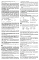
REQUIRED SANDP
APERS
Model
Disc
Attachment
Hole
Sander
Size
Method
Pattern
D26450
5"
PSA
8 Holes
D26451
5"
Hook & Loop
8 Holes
D26453
5"
Hook & Loop
8 Holes
INSTRUCTION MANUAL
GUIDE D'UTILISATION
MANUAL DE INSTRUCCIONES
D26450, D26451, D26453
Random Orbit Palm Sanders
Ponceuse de paume orbitale à mouvement aléatoire
Lijadoras planas de órbita aleatoria
INSTRUCTIVO DE OPERACIÓN, CENTROS DE SERVICIO Y PÓLIZA
DE GARANTÍA.
ADVERTENCIA:
LÉASE ESTE INSTRUCTIVO ANTES
DE USAR EL PRODUCTO.
IF YOU HAVE ANY QUESTIONS OR COMMENTS ABOUT THIS OR ANY D
E
WALT TOOL,
CALL US TOLL FREE AT:
1-800-4-DEWALT (1-800-433-9258)
General Safety Instructions
WARNING! Read and understand all instructions.
Failure to follow all instructions listed
below may result in electric shock, fire and/or serious personal injury.
SAVE THESE INSTRUCTIONS
WORK AREA
•
Keep your work area clean and well lit.
Cluttered benches and dark areas invite accidents.
•
Do not operate power tools in explosive atmospheres, such as in the presence of flam-
mable liquids, gases, or dust.
Power tools create sparks which may ignite the dust or
fumes.
•
Keep bystanders, children, and visitors away while operating a power tool.
Distractions
can cause you to lose control.
ELECTRICAL SAFETY
•
Grounded tools must be plugged into an outlet properly installed and grounded in
accordance with all codes and ordinances. Never remove the grounding prong or
modify the plug in any way. Do not use any adaptor plugs. Check with a qualified elec-
trician if you are in doubt as to whether the outlet is properly grounded.
If the tools
should electrically malfunction or break down, grounding provides a low resistance path to
carry electricity away from the user.
Applicable only to Class I (grounded) tools.
•
Double insulated tools are equipped with a polarized plug (one blade is wider than the
other.) This plug will fit in a polarized outlet only one way. If the plug does not fit fully
in the outlet, reverse the plug. If it still does not fit, contact a qualified electrician to
install a polarized outlet. Do not change the plug in any way.
Double insulation
elim-
inates the need for the three wire grounded power cord and grounded power supply system.
Applicable only to Class II (double insulated) tools.
•
Avoid body contact with grounded surfaces such as pipes, radiators, ranges and
refrigerators.
There is an increased risk of electric shock if your body is grounded.
•
Don’t expose power tools to rain or wet conditions.
Water entering a power tool will
increase the risk of electric shock.
•
Do not abuse the cord. Never use the cord to carry the tools or pull the plug from an
outlet. Keep cord away from heat, oil, sharp edges or moving parts. Replace damaged
cords immediately.
Damaged cords increase the risk of electric shock.
•
When operating a power tool outside, use an outdoor extension cord marked “W-A”
or “W.”
These cords are rated for outdoor use and reduce the risk of electric shock. When
using an extension cord, be sure to use one heavy enough to carry the current your product
will draw. An undersized cord will cause a drop in line voltage resulting in loss of power and
overheating. The following table shows the correct size to use depending on cord length and
nameplate ampere rating. If in doubt, use the next heavier gage. The smaller the gage num-
ber, the heavier the cord.
Minimum Gage for Cord Sets
Volts
Total Length of Cord in Feet
120V
0-25
26-50
51-100
101-150
240V
0-50
51-100
101-200
201-300
Ampere Rating
More
Not more
AWG
Than
Than
0
-
6
18
16
16
14
PERSONAL SAFETY
•
Stay alert, watch what you are doing and use common sense when operating a power
tool. Do not use tool while tired or under the influence of drugs, alcohol, or medication.
A moment of inattention while operating power tools may result in serious personal injury.
•
Dress properly. Do not wear loose clothing or jewelry. Contain long hair. Keep your hair,
clothing, and gloves away from moving parts.
Loose clothing, jewelry, or long hair can be
caught in moving parts. Air vents often cover moving parts and should also be avoided.
D
E
WALT Industrial Tool Co., 701 East Joppa Road, Baltimore, MD 21286
(AUG04) Form No. 624291-00
D26450, D26451, D26453
Copyright © 2004 D
E
WALT
The following are trademarks for one or more D
E
WALT power tools: the yellow and black color
scheme; the “D” shaped air intake grill; the array of pyramids on the handgrip; the kit box con-
figuration; and the array of lozenge-shaped humps on the surface of the tool.
Questions? See us in the World Wide Web at www.dewalt.com