Dewalt DC495B Instruction Manual
Dewalt DC495B Manual
 |
View all Dewalt DC495B manuals
Add to My Manuals
Save this manual to your list of manuals |
Dewalt DC495B manual content summary:
- Dewalt DC495B | Instruction Manual
- Page 1
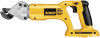
OR COMMENTS CALL US TOLL FREE AT: 1-800-4-DEWALT (1-800-433-9258) JAW REPLACEMENT INSTRUCTIONS DC495 COMPONENTS (FIG. 1) A. Trigger switch/variable speed assembly over and remove top half of head and then remove the blades. To replace blades, place lower jaw (P) onto two pins (R). Apply a thin layer - Dewalt DC495B | Instruction Manual
- Page 2
COMMENTAIRE, APPELEZNOUS À : 1 800 433-9258. INSTRUCTIONS DE REMPLACEMENT DE MÂCHOIRE DC495 COMPOSANTS (fig. 1) A. Détente/Commutateur à vitesses (S), côté conique vers le haut, sur la goupille au sommet du couteau mobile. Replacer la moitié supérieure de la tête (T) sur la moitié inférieure (U)
-
 1
1 -
 2
2
 |
 |
D
E
WALT Industrial Tool Co., 701 East Joppa Road, Baltimore, MD 21286
(DEC06)
Form No. 635693-00
Copyright © 2006 D
E
WALT
The following are trademarks for one or more D
E
WALT power tools: the yellow and black color scheme; the “D” shaped air intake grill; the array of
pyramids on the handgrip; the kit box configuration; and the array of lozenge-shaped humps on the surface of the tool.
IF YOU HAVE ANY QUESTIONS OR COMMENTS CALL US TOLL
FREE AT:
1-800-4-D
E
WALT (1-800-433-9258)
JAW REPLACEMENT INSTRUCTIONS
DC495
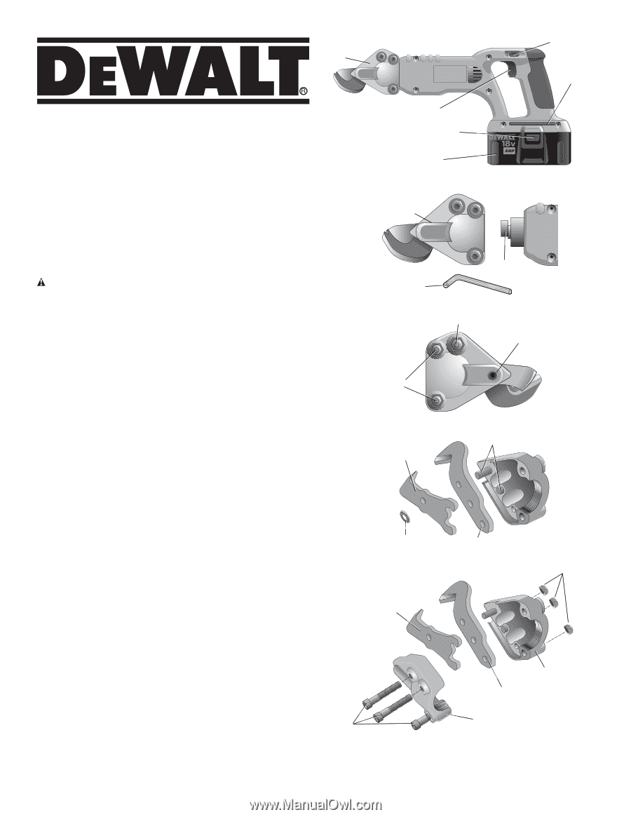
COMPONENTS (FIG. 1)
A. Trigger switch/variable speed switch
B. Swivel head shear
C. On/Lock-off control button
D. Hex wrench
E. Battery pack
F. Battery release buttons
Disassembly and Assembly (Fig. 2–5)
WARNING: Turn unit off and disconnect battery pack before
installing and removing accessories, before adjusting or when
making repairs.
To prevent inadvertant operation, lock the trigger
switch when the tool is not in use and when storing the tool.
To remove shear head from motor,
loosen the two back cap
screws (G) using the hex wrench (D) provided. Remove shear head
(B) from the body by pulling head firmly forward (Fig. 2). Slight
twisting action may be required if head does not slide off easily.
To remove cutter blades from the shear head,
completely loosen
the two back cap screws and remove shear head from motor unit.
Loosen the tensioning screw (O) 1/2 turn. Completely loosen all
three cap screws and remove head assembly. Turn assembly over
and remove top half of head and then remove the blades.
To replace blades,
place lower jaw (P) onto two pins (R). Apply a
thin layer of grease from the packet (included) around the pin and
on the top side of the blade. Place upper jaw (Q) onto pin. Apply the
rest of the grease provided onto the eccentric (L) on the output shaft
of the motor unit and into the area behind the upper moving blade
in the shear head.
Install replacement washer (S), cone side up, over the pin on top of
the moving blade. Place top half of head back (T) onto bottom half
(U), making sure to align the pin to the hole. Reinstall all three cap
screws (G) and nuts (V), but
DO NOT
tighten completely.
Slide shear head back onto motor unit, making sure that the
eccentric engages the moving blade. Once the head is on the motor
unit and aligned, tighten all three screws and follow adjustment
procedure below.
To ensure proper blade tension,
tighten tensioning screw (O) by
turning clockwise to seat the blades. Next, loosen tensioning screw
by turning counterclockwise slightly to allow blade movement.
NOTE
: The tensioning screw should be adjusted to correspond to
material thickness.
A
E
B
C
D
F
L
FIG. 2
B
D
G
(BACK)
(DOS)
(REVERSO)
G (FRONT / AVANT / FRENTE)
O
FIG. 3
FIG. 5
N
G
P
Q
T
U
FIG. 1
FIG. 4
S
P
Q
R