Dewalt DW717 Instruction Manual
Dewalt DW717 Manual
 |
View all Dewalt DW717 manuals
Add to My Manuals
Save this manual to your list of manuals |
Dewalt DW717 manual content summary:
- Dewalt DW717 | Instruction Manual - Page 1
www.dewalt.com INSTRUCTION MANUAL GUIDE D'UTILISATION MANUAL DE INSTRUCCIONES INSTRUCTIVO DE OPERACIÓN, CENTROS DE SERVICIO Y PÓLIZA DE GARANTÍA. ADVERTENCIA: LÉASE ESTE INSTRUCTIVO ANTES DE USAR EL PRODUCTO. DW717 (120 Volt), DW717 (230 Volt) 10" (254 mm) Double Bevel Sliding Compound Miter Saw - Dewalt DW717 | Instruction Manual - Page 2
WITH YOUR SAW 9 CROSSCUTS...10 BEVEL CUTS...10 QUALITY OF CUT ...10 BODY AND HAND POSITION 11 CLAMPING THE WORKPIECE 11 SUPPORT FOR LONG PIECES 11 CUTTING PICTURE FRAMES, SHADOW BOXES AND OTHER FOUR-SIDED PROJECTS 11 CUTTING TRIM MOLDING AND OTHER FRAMES 11 CUTTING COMPOUND MITERS 12 CUTTING - Dewalt DW717 | Instruction Manual - Page 3
outlet. Do not change the plug in any way. Safety Instructions For All Tools WARNING: To reduce the risk of eye injury, ALWAYS use eye protection when operating the miter saw. This miter saw accepts the DEWALT worklight and laser attachments. • KEEP GUARD IN PLACE and in working order. • REMOVE - Dewalt DW717 | Instruction Manual - Page 4
personal injury. • SECURE THE MACHINE TO A STABLE SUPPORTING SURFACE. Vibration can possibly cause the machine to slide, walk, or tip over, causing serious injury. • USE ONLY CROSSCUT SAW BLADES recommended for miter saws. For best results, use only zero-degree or negative hook angles when using - Dewalt DW717 | Instruction Manual - Page 5
cases, other locally obtained work supports, length stops, clamps, etc., may be more appropriate. Use care in selecting and using accessories. Laser Guide System: DW7187 Powered by the saw, the bright laser line delivers enhanced visibility in low and high light locations. Easy to install. Extension - Dewalt DW717 | Instruction Manual - Page 6
designed for this purpose. Unpacking Your Saw Check the contents of your miter saw carton to make sure that you have received all parts. In addition to this instruction manual, the carton should contain: 1. One DW717 miter saw. 2. One DEWALT 10" (254 mm) diameter saw blade. 3. One blade wrench in - Dewalt DW717 | Instruction Manual - Page 7
INSTRUCTIONS Changing or Installing a New Saw Blade (Fig. 3) WARNING: To reduce the risk of serious personal injury, turn off the tool and disconnect it from the power source before attempting to move it, change accessories or make any adjustments accept as written in laser adjustment instructions - Dewalt DW717 | Instruction Manual - Page 8
BEVEL LOCK HANDLE SLIDE STOP BEVEL LATCH LEVER (one each side) BEVEL SCALE LOCK DOWN PIN BLADE WRENCH FIG. 4 BLADE GUARD THUMBSCREW KERF PLATE MITER LATCH BUTTON BEVEL , change accessories or make any adjustments accept as written in laser adjustment instructions. NOTE: Your miter saw is fully - Dewalt DW717 | Instruction Manual - Page 9
, turn off the tool and disconnect it from the power source before attempting to move it, change accessories or make any adjustments accept as written in laser adjustment instructions. In order that the saw can bevel to a full 48º left or right, one of the fences can be adjusted to provide clearance - Dewalt DW717 | Instruction Manual - Page 10
accessories or make any adjustments accept as written in laser adjustment instructions. Inspect carbon brushes regularly by unplugging tool, removing the motor end cap (Fig. 4), lift the brush spring and withdraw the brush assembly. Keep brushes clean and sliding freely in their guides. Always - Dewalt DW717 | Instruction Manual - Page 11
allow the saw to slide along its rails. Miter crosscuts are made with the miter arm at some angle other than zero. This a sharp (60 tooth carbide) blade and a 10 FIG. 13A PROPER CUT FIG. 13B IMPROPER CUTS . Always let the blade come to a full stop before raising arm. If small fibers of wood still - Dewalt DW717 | Instruction Manual - Page 12
move it, change accessories or make any adjustments accept as written in laser adjustment instructions. 11 ALWAYS SUPPORT LONG PIECES. Never use another person as a substitute for a table extension; as additional support for a workpiece that is longer or wider than the basic miter saw table or to - Dewalt DW717 | Instruction Manual - Page 13
compound miter cuts. To use the chart, select the desired angle "A" (Figure 16) of your project and locate that angle on the appropriate arc in the chart. From that point follow the chart straight down to find the correct bevel angle and straight across to find the correct miter angle. Set your saw - Dewalt DW717 | Instruction Manual - Page 14
in the miter angle can be made without affecting the bevel angle. This way, when corners other than 90º are encountered, the saw can be quickly and easily adjusted for them. Use the crown molding fence accessory to maintain the angle at which the molding will be on the wall. INSTRUCTIONS FOR CUTTING - Dewalt DW717 | Instruction Manual - Page 15
inch (391 mm)] workpieces when a special set up is used. To set the saw up for these workpieces, follow these steps: 1. Remove both left and right sliding fences from the saw and set aside. To remove them, unscrew the fence knobs several turns and slide each fence outward. Adjust and lock the miter - Dewalt DW717 | Instruction Manual - Page 16
,563 5,582,089 5,199,343 Other patents may be pending. Troubleshooting Guide BE SURE TO FOLLOW SAFETY RULES AND INSTRUCTIONS TROUBLE! WHAT'S WRONG? WHAT TO DO SAW WILL NOT START 1. Saw not plugged in 1. Plug in saw 2. Fuse blown or circuit breaker 2. Replace fuse or reset circuit breaker - Dewalt DW717 | Instruction Manual - Page 17
THIS MITER ANGLE ON SAW TABLE 1 COMPOUND MITER CUT (Position wood with broad flat side on the table and the narrow edge against the fence.) 10 20 30 40 10 20 10 20 30 30 40 6-SIDED BOX 50 40 8-SIDED BOX 60 50 60 70 80 70 80 50 SQUARE BOX 60 70 80 SET THIS BEVEL - Dewalt DW717 | Instruction Manual - Page 18
Français TABLE DES MATIÈRES INSTRUCTIONS RELATIVES À LA DOUBLE ISOLATION ET À LA FICHE POLARISÉE 18 RÈGLES DE 24 AJUSTEMENT DROIT ET GAUCHE DE 45 º DE LA BUTÉE DE BISEAU ...........24 AJUSTEMENT DU GUIDE 25 FREIN ÉLECTRIQUE AUTOMATIQUE 25 ACTIVATION ET VISIBILITÉ DU PARE-MAIN 25 RÉGLAGE DE LA - Dewalt DW717 | Instruction Manual - Page 19
connexion à la terre. • REMARQUE : la double isolation ne remplace pas les précautions normales de à onglets est compatible avec la lampe de travail et le laser DEWALT. • MAINTENIR LE PROTÈGE-LAME EN PLACE et en é pièce sur la table et contre le guide. Faire de même lorsque le travail à effectuer - Dewalt DW717 | Instruction Manual - Page 20
V 240 V Intensité nominale Plus de Pas plus de 0- 6 6 - 10 10 - 12 12 - 16 Calibre minimal pour rallonge Longueur totale du cordon en mè avec un autre outil. Une liste des accessoires recommandés se par la table et le guide). Tenir la pièce à travailler fermement contre le guide et la table. Une - Dewalt DW717 | Instruction Manual - Page 21
SUR UNE SURFACE DE SUPPORT STABLE. Les vibrations sont . • UTILISER SEULEMENT DES LAMES DE DIMENSION ET DE TYPE APPROPRIÉS prévues pour tement lu et compris les instructions.. AVERTISSEMENT : Toujours porter PLACE SUR LA TABLE ET CONTRE LE GUIDE. AVERTISSEMENT : Certaines poussières produites par - Dewalt DW717 | Instruction Manual - Page 22
être utiles. Dans certains cas, d'autres supports d'ouvrage, butées réglables, fixations, etc. peuvent être plus appropriés. Faites attention lors du choix et de l'utilisation d'accessoires Système guidé par laser : DW7187 Alimenté par la scie, le trait laser brillant améliore la visibilité dans les - Dewalt DW717 | Instruction Manual - Page 23
est conçue pour accepter deux supports d'ouvrage, un de chaque de la sciure produite (non illustré). Guide de moulures couronnées : DW7084 1. Une scie à onglet DW717. 2. Une lame de scie DEWALT de 254 mm (10 po) de diamètre. ou gauche à 45 º. Note: Your saw is capable of cutting the following once a - Dewalt DW717 | Instruction Manual - Page 24
scie. 2. Tout en maintenant le bras et le support du pare-main relevés et le pare-main ceux indiqués dans les directives sur le réglage par laser. REMARQUE : Votre scie à onglet est réglée en CHELLE D'ONGLET (FIG. 5) Placez une équerre contre le guide de la scie et contre la lame, comme illustré. ( - Dewalt DW717 | Instruction Manual - Page 25
vis qui maintiennent l'échelle d'onglet sur la base et déplacez l'échelle vers la gauche ou la droite jusqu'à ce que la lame soit perpendiculaire au guide, en vous servant de l'équerre. Resserrez les quatre vis. Ne prêtez pas encore attention à la valeur lue sur le pointeur de l'onglet. RÉGLAGE DU - Dewalt DW717 | Instruction Manual - Page 26
sur le réglage par laser. Afin que la scie puisse biseauter à 48 degrés vers la gauche ou la droite, l'un des guides doit être ajusté fois. Si le problème persiste, faites réparer l'outil par un centre de service agréé DEWALT. Assurez-vous toujours que la lame s'est arrêtée avant de la retirer du - Dewalt DW717 | Instruction Manual - Page 27
ceux indiqués dans les directives sur le réglage par laser. Inspectez régulièrement les brosses en carbone : elles glissent librement dans leurs guides. Replacez toujours dans son support une brosse utilisée dans service DEWALT. Laissez l'outil « tourner à blanc » (tourner sans charge) pendant 10 - Dewalt DW717 | Instruction Manual - Page 28
fermement le bois en place sur la table et contre le guide. Après avoir serré la poignée de blocage de rail, ,8 mm (4,4 po.) [76,2 mm (3 po.) 45º miter] avec un onglet à 45 degrés, utilisez un mouvement exté avec des coups de scie réduits, la lame du DW717 s'étend plus profondément dans la table. Il - Dewalt DW717 | Instruction Manual - Page 29
de coupe, consultez la liste de lames de scie recommand directives sur le réglage par laser. AVERTISSEMENT : Une pièce DW717. Pour vous procurer le DW7082, contactez votre revendeur local ou un centre de service DEWALT blanc avant d'entamer la coupe. Les guides de gauche et de droite coulissent d'un - Dewalt DW717 | Instruction Manual - Page 30
dans les directives sur le réglage par laser. SOUTENEZ TOUJOURS LES PIÈCES LONGUES. tirer. Pour optimiser le résultat, utiliser le support DW7080 de travail en extension afin d'augmenter la type d'assemblage, réglez FIG. 19 GUIDE CORRECT FIG. 20 LAME LAME GUIDE INCORRECT le biseau sur zéro et - Dewalt DW717 | Instruction Manual - Page 31
PAS DE CÔTÉ 4 5 6 7 8 9 10 - EXEMPLES ONGLET OU BISEAU D'ANGLE 45° 36° 30° 25.7° 22.5° 20° 18 illustré à la figure 11. Toutes les coupes doivent être réalisées avec l'arrière de la moulure contre le guide et la base de la moulure contre la base COIN INTÉRIEUR : Côté gauche 1. Onglet gauche à 45 ° 2. - Dewalt DW717 | Instruction Manual - Page 32
formera la moulure avec le mur. INSTRUCTIONS POUR LA DÉCOUPE DE MOULURES COURONNÉES MISES EN ANGLE ENTRE LE GUIDE ET LA BASE DE LA SCIE POUR (celle qui sera adossée au mur lors de l'installation) se trouve contre le guide et que sa partie supérieure repose sur la base de la scie, comme illustr - Dewalt DW717 | Instruction Manual - Page 33
pour durer plusieurs années. Si elles ont besoin d'être remplacées, suivez les instructions de la Page 26 ou retournez l'outil au centre de service le plus proche pour réparation. Une liste des centres de service est livrée avec l'outil. Information sur les réparations ou l'entretien Avoir en main - Dewalt DW717 | Instruction Manual - Page 34
outils DEWALT sont couverts par notre : SERVICE D'ENTRETIEN GRATUIT DE 1 AN DEWALT entretiendra outil électrique, laser ou de votre marteau-cloueur DEWALT pour quelque raison 089 5,199,343 D'autres brevets peuvent être en instance. Guide de dépannage VEILLEZ À SUIVRE LES RÈGLES ET CONSIGNES DE - Dewalt DW717 | Instruction Manual - Page 35
SCIE TABLEAU 1 COUPE À ONGLET MIXTE (Positionnez le morceau de bois avec le large côté plat contre la table et l'arête étroite contre le guide.) 10 20 30 40 10 20 10 20 30 30 40 BOÎTE À 6 FACES 50 40 50 BOÎTE À 8 FACES 60 60 70 80 70 80 BOÎTE 50 CARR - Dewalt DW717 | Instruction Manual - Page 36
ÍNDICE DE TEMAS INSTRUCCIONES SOBRE DOBLE AISLAMIENTO / ENCHUFE POLARIZADO .....36 INSTRUCCIONES DE SEGURIDAD PARA TODAS LAS HERRAMIENTAS............36 NORMAS DE SEGURIDAD ADICIONALES 37 CONEXIÓN ELÉCTRICA 39 ACCESORIOS ...39 DESCRIPCIONES DE LAS HOJAS 40 CÓMO DESEMBALAR LA SIERRA 40 - Dewalt DW717 | Instruction Manual - Page 37
describen el nivel de gravedad de cada palabra de señal. Lea el manual y preste atención a estos símbolos. PELIGRO: indica una situación de ingletadora es compatible con los suplementos láser y de luz de trabajo DEWALT. • MANTENGA EL PROTECTOR INSTALADO ADECUADAMENTE y en funcionamiento. • RETIRE LAS - Dewalt DW717 | Instruction Manual - Page 38
amperios Desde Hasta: AWG 0- 6 18 16 16 14 6 - 10 18 16 14 12 10 - 12 16 16 14 12 12 - 16 14 12 No otra herramienta. Consulte el manual de instrucciones para obtener UTILICE DISCOS ABRASIVOS. El calor en exceso y las partículas abrasivas que estos discos generan pueden dañar - Dewalt DW717 | Instruction Manual - Page 39
Seguridad Ocupacional de EE.UU.) apropiada para la exposición al polvo. Aleje las partículas de la cara y el cuerpo. Para su comodidad y seguridad, la EN LA CUBIERTA DEL MOTOR: ADVERTENCIA: POR SU PROPIA SEGURIDAD, LEA EL MANUAL DE INSTRUCCIONES ANTES DE OPERAR LA SIERRA. AL REPARAR, SÓLO UTILICE - Dewalt DW717 | Instruction Manual - Page 40
de potencia y sobrecalentamiento. Todas las herramientas DEWALT están probadas en fábrica. Si esta áctico vaciado, la bolsa para polvo recoge la mayor parte del aserrín generado (no se muestra). Reborde para de corona. Sistema de luz de trabajo LED: DWS7085 Iluminación usada para mayor visibilidad y - Dewalt DW717 | Instruction Manual - Page 41
Además de este manual de instrucciones, la caja debe contener: 1. Una sierra ingletadora DW717. 2. Una hoja de sierra DEWALT de 254 mm (10 pulg.) de diá asegúrese de que los tornillos de montaje no sobresalgan de la parte inferior de la madera. La madera contrachapada debe quedar bien estabilizada - Dewalt DW717 | Instruction Manual - Page 42
TAPA DE EXTREMO DEL MOTOR MANGO DE ELEVACIÓN REGULACIÓN DEL TORNILLO DE SUJECIÓN DE RIELES CUBIERTA DEL MOTOR PERILLA DE BLOQUEO DE RIEL PALANQUITA DE BLOQUEO DE BISEL TOPE DESLIZANTE PALANCA CERROJO DE BISEL (una a cada lado) ESCALA DE BISEL PESTILLO DE SEGURIDAD LLAVE DE HOJA FIG. 4 - Dewalt DW717 | Instruction Manual - Page 43
ón del reborde antes de transportar la sierra. Para poder transportarla fácilmente de un lugar a otro, se ha incorporado una agarradera de transporte en la parte superior del brazo de la sierra y asideros en la base, como se muestra en la Figura 4. Ajustes ADVERTENCIA: Para reducir el riesgo de - Dewalt DW717 | Instruction Manual - Page 44
haga reparar la herramienta en un centro de servicio DEWALT autorizado. 43 Asegúrese siempre de que la hoja , usted puede elevar el protector en forma manual. NUNCA ELEVE EL PROTECTOR DE LA HOJA MANUALMENTE la barra de bloqueo de inglete (Fig. 10). Con un destornillador de cabeza plana, ajuste la - Dewalt DW717 | Instruction Manual - Page 45
no gire. Ajuste la tuerca de seguridad. FIG. 10 BARRA DE BLOQUEO DE INGLETE TUERCA DE SEGURIDAD Cepillos habrá que reemplazarlo. Utilice solamente cepillos DEWALT idénticos. Es fundamental utilizar cepillos corte de la ranura. Moviendo la palanca hacia la parte de atrás de la sierra se desvía el tope - Dewalt DW717 | Instruction Manual - Page 46
hacia atrás para completar el corte. No permita que la sierra toque la parte superior de la pieza de trabajo mientras la retira. La sierra podría correrse una mayor capacidad de cortes transversales con menor carrera, la hoja de la DW717 se extiende más hacia el centro de la mesa. Como resultado, es - Dewalt DW717 | Instruction Manual - Page 47
con la DW717. Para comprar la DW7082, comuníquese con el comercio minorista de su localidad o con el centro de servicios DEWALT. También pueden el orificio detrás de la guía. La abrazadera debe estar mirando hacia la parte posterior de la sierra ingletadora. La ranura en la barra de la abrazadera - Dewalt DW717 | Instruction Manual - Page 48
O BISEL 4 45° 5 36° 6 30° 7 25.7° 8 22.5° 9 20° 10 18° FIG. 17 REBORDE MESA MOLDURA DE CORONA PLANA SOBRE LA MESA Y CONTRA EL REBORDE De la misma manera, siga la línea de intersección vertical hacia la parte superior o inferior para obtener la regulación de ángulo de bisel en - Dewalt DW717 | Instruction Manual - Page 49
estándar (EE.UU) con ángulos de 52 y 38 grados. CONFIGURACIÓN DE BISEL TIPO DE CORTE LADO IZQUIERDO, ESQUINA INTERIOR: 33,85° izquierda 1. Parte superior de la moldura contra el reborde 2. Mesa de inglete a 31,62° a la derecha 3. Conserve el extremo izquierdo del corte LADO DERECHO, ESQUINA - Dewalt DW717 | Instruction Manual - Page 50
puede conseguir en el comercio minorista DEWALT de su localidad o en el centro de servicios DEWALT. Determinadas piezas de trabajo, debido de la hoja. De ser así, simplemente coloque su pulgar derecho en la parte superior del protector y enróllelo hacia arriba lo suficiente para despejar la pieza - Dewalt DW717 | Instruction Manual - Page 51
una plataforma usando una pieza de 38 mm (1,5 pulg.) de espesor de una placa de partículas o madera espesa similar plana y fuerte de 38 mm, con las siguientes dimensiones: su garantía y adquirir partes, refacciones y accesorios originales. Garantía limitada de tres años DEWALT reparará sin cargo - Dewalt DW717 | Instruction Manual - Page 52
en México, por favor llame al (55) 5326 7100 Si se encuentra en U.S., por favor llame al 1-800-433-9258 (1-800 4-DEWALT) Especificaciones DW717 Tensión de alimentación: 120 V AC Consumo de corriente: 15 A Frecuencia de alimentación: 60 Hz Potencia nominal: 1 600 W Rotación sin carga - Dewalt DW717 | Instruction Manual - Page 53
Guía para solucionar problemas ASEGÚRESE DE SEGUIR LAS REGLAS E INSTRUCCIONES DE SEGURIDAD PROBLEMA: ¿QUÉ SUCEDE? QUÉ HACER... LA SIERRA NO SE ENCIENDE 1. La sierra no está enchufada 2. Fusible quemado o interruptor automático activado 1. Enchufe la sierra 2. Reemplace el fusible o reinicie - Dewalt DW717 | Instruction Manual - Page 54
SIERRA TABLA 1 CORTE DE INGLETE COMPUESTO (Ubique la madera con el lado plano ancho sobre la mesa y el borde angosto contra el reborde.) 10 20 30 40 10 20 10 20 30 30 CAJA 40 DE SEIS 40 CAJA DE OCHO 50 50 LADOS LADOS 60 60 70 70 80 80 CAJA 50 - Dewalt DW717 | Instruction Manual - Page 55
- Dewalt DW717 | Instruction Manual - Page 56
Industrial Tool Co., 701 East Joppa Road, Baltimore, MD 21286 (JUN08) Part No. 658046-00 DW717 Copyright © 2008 DEWALT The following are trademarks for one or more DEWALT power tools: the yellow and black color scheme; the "D" shaped air intake grill; the array of pyramids on the handgrip; the
-
 1
1 -
 2
2 -
 3
3 -
 4
4 -
 5
5 -
 6
6 -
 7
7 -
8
-
9
-
10
-
11
-
12
-
13
-
14
-
15
-
16
-
17
-
18
-
19
-
20
-
21
-
22
-
23
-
24
-
25
-
26
-
27
-
28
-
29
-
30
-
31
-
32
-
33
-
34
-
35
-
36
-
37
-
38
-
39
-
40
-
41
-
42
-
43
-
44
-
45
-
46
-
47
-
48
-
49
-
50
-
51
-
52
-
53
-
54
-
55
-
56
 |
 |

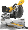
DW717 (120 Volt), DW717 (230 Volt) 10" (254 mm) Double Bevel Sliding Compound Miter Saw
DW717 (120 Volt), DW717 (230 Volt) Scie coulissante à onglet mixte 254 mm (10 po)
DW717 (120 Voltios), DW717 (230 Voltios) Sierra ingletadora compuesta deslizante de
doble bisel de 254 mm (10 pulg.)
INSTRUCTION MANUAL
GUIDE D’UTILISATION
MANUAL DE INSTRUCCIONES
INSTRUCTIVO DE OPERACIÓN, CENTROS DE SERVICIO Y PÓLIZA
DE GARANTÍA.
ADVERTENCIA:
LÉASE ESTE INSTRUCTIVO ANTES
DE USAR EL PRODUCTO.
Questions? See us on the World Wide Web at www.dewalt.com
Before returning this product call
1-800-4-D
E
WALT
IF YOU SHOULD EXPERIENCE A PROBLEM WITH YOUR D
E
WALT PURCHASE,
CALL 1-800-4 D
E
WALT
IN MOST CASES, A D
E
WALT REPRESENTATIVE CAN RESOLVE YOUR
PROBLEM OVER THE PHONE.
IF YOU HAVE A SUGGESTION OR COMMENT, GIVE US A CALL.
YOUR FEEDBACK IS VITAL TO THE SUCCESS OF D
E
WALT’S QUALITY
IMPROVEMENT PROGRAM.