EVGA 121-BL-E756-TR Visual Guide
EVGA 121-BL-E756-TR Manual
 |
View all EVGA 121-BL-E756-TR manuals
Add to My Manuals
Save this manual to your list of manuals |
EVGA 121-BL-E756-TR manual content summary:
- EVGA 121-BL-E756-TR | Visual Guide - Page 1
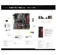
Micro VISUAL GUIDE The following quick steps will guide you through testing the absolute bare minimum essentials of your motherboard . After removing the EVGA X58 SLI® Micro from its packaging, connect your 24-Pin ATX Power Connector and 8-Pin CPU Power Connector to the motherboard. • a. SATA - EVGA 121-BL-E756-TR | Visual Guide - Page 2
Micro VISUAL GUIDE 4 24 Pin ATX Power 3; ; RX- TX- FIX support long term stability. vV`7A® Premium Services Advanced RMA: Protect yourself and accelerate the RMA process. www.evga.com/EAR 1+1 Warranty: Register the purchased product within 30 days to receive 2 year warranty. www.evga.com/warranty
-
 1
1 -
 2
2
 |
 |
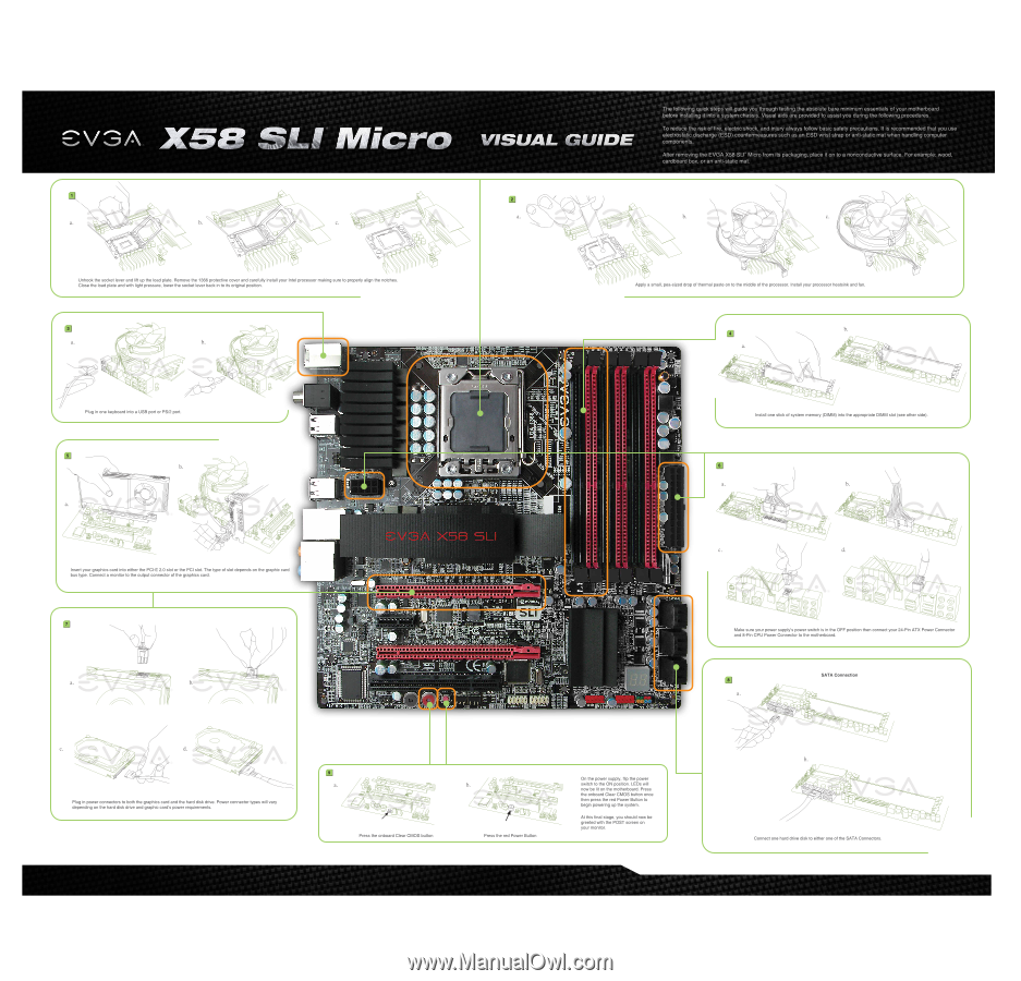
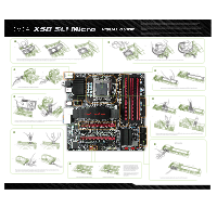
The
following
quick
steps
will
guide
you
through
testing
the
absolute
bare
minimum
essentials
of
your
motherboard
before
installing
it
into
a
system
chassis.
Visual
aids
are
provided
to
assist
you
during
the
following
procedures.
CVGA
X5P
"ILI
Micro
VISUAL
GUIDE
To
reduce
the
risk
of
fire,
electric
shock,
and
injury
always
follow
basic
safety
precautions.
It
is
recommended
that
you
use
electrostatic
discharge
(ESD)
countermeasures
such
as
an
ESD
wrist
strap
or
anti
-static
mat
when
handling
computer
components.
After
removing
the
EVGA
X58
SLI®
Micro
from
its
packaging,
place
it
on
to
a
nonconductive
surface.
For
example:
wood,
cardboard
box,
or
an
anti
-static
mat.
a.
b.
c.
'
2
0
Unhook
the
socket
lever
and
lift
up
the
load
plate.
Remove
the
1366
protective
cover
and
carefully
install
your
Intel
processor
making
sure
to
properly
align
the
notches.
Close
the
load
plate
and
with
light
pressure,
lower
the
socket
lever
back
in
to
its
original
position.
r
•
a.
a.
b.
Plug
in
one
keyboard
into
a
USB
port
or
PS/2
port.
b.
ot
1
0
Insert
your
graphics
card
into
either
the
PCI-E
2.0
slot
or
the
PCI
slot.
The
type
of
slot
depends
on
the
graphic
card
bus
type.
Connect
a
monitor
to
the
output
connector
of
the
graphics
card.
C.
a.
O
m©
d.
b.
O
Plug
in
power
connectors
to
both
the
graphics
card
and
the
hard
disk
drive.
Power
connector
types
will
vary
depending
on
the
hard
disk
drive
and
graphic
card's
power
requirements.
a.
cab
1,1
.
1%
Cj
•
•
•
•
It
‘
IC•Iti•Ont
•
,,-
AIM
I
re
i
I •
es
.030
•
Rtlail
•
10
'3
R34
004
0
11
34
‘
-t
.*.»
•
414
11
dRiaRiit
MIMI
§
•
a
s
ta
aat~nnumu
•
l
llll
:I
=•
Tlfi?liliflitifffititiffh
REV:0.0
nal;
O
wa
iv
2:A
•
iiiii
iiiiiii
rt.
".
4
4-4.•••
.
zz
3
"k20.1
•
Gs
5
F,
t214
02,0
arl
I
SDI
kit
fupj
,
4iii
di:47
•3
8
111:4
•1N,
I. .
>1
czszezocxecast
C34.7C2114C103C380
C244C1414C301021
conconannn
oecomancoo
camocomon
conconamon
croocna
can
30
41
•••
1•002.
"."••
1.15
••33
0434
0007
wi
g
elm
p01
lad
oil:
dV1
4
3
:
I!
*
0
4
444
.
N•
III
MEMOR
it
ir3iint33
ii
ay
ePCIE
X16
1
r•
*act*
liomovuo
0
131
Iyzt
CYI
Weal,
SI
RI•301.
tc
3
1.441
474
on
41.1
sa
t
so=
l`t
3
'4
4
455P
0
mows:NA,
L
C
VI
T
I.
11:7CC
.
3
I
••••••""
i
ds
2
*EXCI
*"
IP
0001
4
al
.
74
API •04ra
4,7
ICC
USE
9•34
cm
ca.
•
6
4*0-gesair
•
dial
id
#ribill*16:
diP
a
.....
..
.
IS
.,
lllllllllllllllllllllllllllllllllllllllll
MIMS
-
IP°n
•
,
.;ena
lEcto•
r‘..
V
K
t1
4
cE
—
MOM%
=am
3ii]i3
raet
VOW..
•
Cs:*
al
#1
I
.
S
FAN
boa
33
••••4444••44•
4
2,
C4•4
a
...it
4
3.•
a;.=
•
4
,
1
1
1
1 1 1
'gar
Mlnrf
iia
it
V
••••3
CAN
44141
GUS
11
cant
:
w
O
b.
o
c.
Apply
a
small,
pea
-sized
drop
of
thermal
paste
on
to
the
middle
of
the
processor.
Install
your
processor
heatsink
and
fan.
Pr
en
•
Ca••
•07
.
,S
I
OM
I
6
a
,
lit
',V
4P4
1
‘
143
,
1
"
•-`,"
SATA0/1
•
•
a.
b.
O
Press
the
onboard
Clear
CMOS
button
Press
the
red
Power
Button
On
the
power
supply,
flip
the
power
switch
to
the
ON
position.
LEDs
will
now
be
lit
on
the
motherboard.
Press
the
onboard
Clear
CMOS
button
once
then
press
the
red
Power
Button
to
begin
powering
up
the
system.
At
this
final
stage,
you
should
now
be
greeted
with
the
POST
screen
on
your
monitor.
b.
a.
iOQ
0
/7
o<>
J
270
L
..
Install
one
stick
of
system
memory
(DIMM)
into
the
appropriate
DIMM
slot
(see
other
side).
a.
b.
c.
00
00
"709
4
6:22r,,,,
O 5
0
0
d.
S
O
O
Make
sure
your
power
supply's
power
switch
is
in
the
OFF
position
then
connect
your
24
-Pin
ATX
Power
Connector
and
8
-Pin
CPU
Power
Connector
to
the
motherboard.
•
a.
b.
00
O
SATA
Connection
,
0
6,60
,9
.
VOa
O` QO
Q
OO
p~~
Connect
one
hard
drive
disk
to
either
one
of
the
SATA
Connectors.