EVGA 123-YW-E175-A1 User Manual
EVGA 123-YW-E175-A1 - nForce 750i SLI FTW Motherboard Manual
 |
UPC - 843368004507
View all EVGA 123-YW-E175-A1 manuals
Add to My Manuals
Save this manual to your list of manuals |
EVGA 123-YW-E175-A1 manual content summary:
- EVGA 123-YW-E175-A1 | User Manual - Page 1
- EVGA 123-YW-E175-A1 | User Manual - Page 2
User Guide EVGA nForce 750i SLI Motherboard - EVGA 123-YW-E175-A1 | User Manual - Page 3
of the Kit vi EVGA nForce 750i Motherboard 1 Motherboard Specifications 1 Motherboard Specifications continued 2 UnPacking and Parts Description 3 Equipment ...4 Motherboard Internal Connectors and Back Panel Connectors 5 I/O Panel description...6 Safety Instructions...6 Preparing the - EVGA 123-YW-E175-A1 | User Manual - Page 4
19 PCI Express x16 Slots 19 Onboard Buttons ...20 Configuring the BIOS 21 Enter BIOS Setup 21 Main Menu...22 Standard CMOS Features Menu 22 Date and SATA Channel 23 Drive A...23 Halt On ...23 Memory ...23 Advanced BIOS Features 24 Removable Device Priority 24 Hard Disk Boot Priority 25 Quick - EVGA 123-YW-E175-A1 | User Manual - Page 5
Advanced Chipset Features 26 Spread Spectrum 26 System BIOS Cacheable 26 Integrated Peripherals Menu 27 IDE Function Setup 27 RAID Config ...28 USB Config...28 MAC Config ...28 HD Audio ...29 IEEE1394 controller 29 - EVGA 123-YW-E175-A1 | User Manual - Page 6
& Memory Config 36 FSB Memory Clock Mode 36 Memory Timing Settings 37 System Voltages 38 CPU Core ...38 CPU FSB...38 System Monitor Menu Installing Drivers and Software Driver Installation Appendix A. POST Codes - EVGA 123-YW-E175-A1 | User Manual - Page 7
to install and connect your new EVGA nForce® 750i SLI motherboard. However, it does not contain the following items that must be purchased separately to make the motherboard functional. Intel microprocessor: Intel Core 2 Extreme, Intel Core 2 Quad, Intel Core 2 Duo Pentium EE, Pentium D, Pentium - EVGA 123-YW-E175-A1 | User Manual - Page 8
. Motherboard Specifications Size ATX form factor of 245mm x 305mm Microprocessor support Intel Core 2 Extreme, Intel Core 2 Quad, Intel Core 2 Duo, Pentium EE, Pentium D, Pentium Operating systems: Supports Windows XP 32bit/64bit and Windows Vista 32bit/64bit Contains NVIDIA nForce 750i SLI MCP - EVGA 123-YW-E175-A1 | User Manual - Page 9
nForce 750i SLI Motherboard Onboard Audio Azalia High-Definition audio Supports 8-channel audio Supports S/PDIF output Supports Jack-Sensing function Green Function Supports ACPI (Advanced Configuration and Power Interface) Supports S0 (normal), S1 (power on suspend), S3 (suspend to RAM), S4 ( - EVGA 123-YW-E175-A1 | User Manual - Page 10
lead-free) parts. Equipment The following equipment is included in the NVIDIA nForce 750i SLI motherboard box. NVIDIA nForce 750i SLI Motherboard This PCI Express motherboard contains the NVIDIA nForce 750i SLI SPP and MCP and is SLI-ready. I/O Shield Installs in the chassis to block radio frequency - EVGA 123-YW-E175-A1 | User Manual - Page 11
Cable Provides four additional USB ports to either the front or back panels of the chassis. SATA Signal Cable (Qty Four) Used to support the Serial ATA protocol and each one connects a single drive to the motherboard Comm2 Bracket Cable IDE-ATA 133 HDD Cable Driver Installation CD SLI Bridge 2-Way - EVGA 123-YW-E175-A1 | User Manual - Page 12
- EVGA 123-YW-E175-A1 | User Manual - Page 13
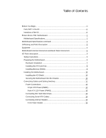
nForce 750i SLI Motherboard 1. CPU 775 Socket 2. CPU fan connector 3. DDR2 DIMM slots 0 - 3 4. 24-pin ATX power connector 5. IDE connector 6. Chipset fan connector 1 7 2 3 4 5 6 4 4 Figure 2. EVGA nForce 750i SLI Backpanel connectors 1. PS/2 Mouse Port 2. PS/2 Keyboard Port 3. 1394a ( - EVGA 123-YW-E175-A1 | User Manual - Page 14
section will guide you through the installation of the motherboard. The topics covered in this section are: Preparing the motherboard Installing the CPU Installing the CPU fan Installing the memory Installing the motherboard Connecting cables and setting switches Safety Instructions To reduce - EVGA 123-YW-E175-A1 | User Manual - Page 15
nForce 750i SLI Motherboard Installing the CPU Be very careful when handling the CPU. Make sure not to bend or break any pins on the back. Hold the processor only by the edges and do not touch the bottom of the processor. Use the following procedure to install the CPU onto the motherboard. 1. - EVGA 123-YW-E175-A1 | User Manual - Page 16
EVGA Installing Memory DIMMs Your new motherboard has four 1.8V 240-pin slots for DDR2 memory. These slots support 256 MB, 512 MB, 1 GB, and 2 GB DDR2 memory modules. They also support dual channel DDR2 memory technology up to 10.7GB/s. There must be at least one memory bank populated to ensure - EVGA 123-YW-E175-A1 | User Manual - Page 17
nForce 750i SLI Motherboard Installing the Motherboard The sequence of installing the motherboard into the chassis depends on the chassis you are using and if you are replacing an existing motherboard or working with an empty chassis. Determine if it would be easier to make all the connections prior - EVGA 123-YW-E175-A1 | User Manual - Page 18
EVGA Connecting Cables and Setting Switches This section takes you through all the connections and switch settings necessary on the motherboard. This will include: Power Connections 24-pin ATX power 8-pin ATX 12V power Internal Headers Front panel IEEE 1394a USB headers Audio Speaker COM FDD IDE - EVGA 123-YW-E175-A1 | User Manual - Page 19
nForce 750i SLI Motherboard Power Connections 24-pin ATX Power PWR1 is the main power supply connector located along the edge of the board next to the DIMM slots. Make sure that the power supply cable and pins are properly aligned with the connector on the motherboard. Firmly plug the power supply - EVGA 123-YW-E175-A1 | User Manual - Page 20
EVGA Connecting IDE Hard Disk Drives The IDE connector supports Ultra ATA 133/100/66 IDE hard disk drives. 1. Connect the blue connector (the cable end with a single connector) to the motherboard. 2. Connect the black connector (the cable with the two closely spaced black and gray connectors) to - EVGA 123-YW-E175-A1 | User Manual - Page 21
nForce 750i SLI Motherboard Connecting Serial ATA Cables The Serial ATA II connector is used to connect the Serial ATA II device to the motherboard. These connectors support the thin Serial ATA II cables for primary storage devices. The current Serial ATA II interface allows up to 300MB/s data - EVGA 123-YW-E175-A1 | User Manual - Page 22
EVGA Connecting Internal Headers Front Panel Header The front panel header on this motherboard is one connector used to connect the following four cables. (see Table 2 for pin definitions): PWRLED Attach the front panel power LED cable to these - EVGA 123-YW-E175-A1 | User Manual - Page 23
nForce 750i SLI Motherboard IEEE 1394a The IEEE 1394 expansion cable bracket is with the front panel option). 2. Connect the two ends of the cables to the IEEE 1394 connectors on the motherboard. v Pin Assignments Connector Pin Signal 1 TPA+ 3 GND 5 TPB+ 7 +12V 9 Empty Pin Signal 2 TPA4 - EVGA 123-YW-E175-A1 | User Manual - Page 24
Rear Audio. The front Audio supports re-tasking function. v Pin Assignments Connector Pin Signal Pin Signal 1 PORT1_L 2 AUD_GND 3 PORT1_R 4 PRECENCE_J 5 PORT2_R 6 SENSE1_RETURN 7 SENSE_SEND 8 Empty 9 PORT2_L 10 SENSE2_RETURN COM1 The motherboard kit provides an additional serial COM - EVGA 123-YW-E175-A1 | User Manual - Page 25
CPU fan cable can be either a 3-pin or a 4-pin connector. Connect a 3-pin connector to pins 1, 2, and 3 on the motherboard connector. CHASSIS FAN2 NFORCE FAN: Install the fan over the nForce 750i SLI SPP to draw heat from the MCP. The fans plug into a 3-pin connector. SYS FAN AUX FAN CHASSIS - EVGA 123-YW-E175-A1 | User Manual - Page 26
Expansion Slots The EVGA nForce 750i SLI motherboard contains six expansion slots, three PCI Express slots and three PCI slots. For a full list of PCI Express x16 graphics card supported by this motherboard, go to www.nvidia.com/estore. PCI Slots The three PCI slots support many expansion cards - EVGA 123-YW-E175-A1 | User Manual - Page 27
nForce 750i SLI Motherboard Onboard Buttons These onboard buttons include RESET, POWER and CMOS system easily, it is especially handy for debugging or testing the system. CMOS Button: The motherboard uses the CMOS RAM to store all the set parameters. The CMOS can be cleared by press the CMOS button. - EVGA 123-YW-E175-A1 | User Manual - Page 28
nForce 750i SLI Motherboard Configuring the BIOS This section discusses how to change the system settings through the BIOS Setup menus. Detailed descriptions of the BIOS parameters are also provided. This section includes the following information: Enter BIOS Setup Main Menu Standard CMOS Features - EVGA 123-YW-E175-A1 | User Manual - Page 29
EVGA Main Menu The main menu allows you to select from the list Date, Hard Disk Type.., Standard CMOS Features Use this menu to set up the basic system configuration. Advanced BIOS Features Use this menu to set up the advanced system features and boot sequence. Advanced Chipset Features Use this - EVGA 123-YW-E175-A1 | User Manual - Page 30
nForce 750i SLI Motherboard , change, and disable the password used to access the BIOS menu. Save & Exit Setup Use this command to save Channel 0 Master IDE Channel 0 Slave SATA Channel 1 (A0) Master SATA Channel 2 (A1) Master SATA Channel 3 (B0) Master SATA Channel 4 (C1) Master Sat, Jul 01 - EVGA 123-YW-E175-A1 | User Manual - Page 31
a halt instruction. Execute Disable Bit When this function is disabled, it forces the XD feature flag to always return to zero (0). Virtualization Technology When this function is enabled, it allows a VMM to utilize the additional hardware capabilities provided by Intel Virtualization Technology - EVGA 123-YW-E175-A1 | User Manual - Page 32
nForce 750i SLI Motherboard the + or - keys to move the device priority up or down in the list. To go back to the previous menu, press Esc. The Options - EVGA 123-YW-E175-A1 | User Manual - Page 33
EVGA MPS Version Control For OS Use this function to select the Multi-Processor Specification (MPS) version that BIOS passes to the AwardBIOS CMOS Setup Utility Advanced Chipset Features Spread Spectrum Control System BIOS Cacheable [Press Enter] [Disabled] Item Help Main Level Voltage - EVGA 123-YW-E175-A1 | User Manual - Page 34
nForce 750i SLI Motherboard Integrated Peripherals Menu Select Integrated Peripherals from the CMOS Setup Integrated Peripherals IDE Function Setup RAID Cofig OnChip USB USB Keyboard/Storage Support USB Mouse Support USB Park Mode USB TD Reads USB Periodic Data Reads USB Asyn - EVGA 123-YW-E175-A1 | User Manual - Page 35
EVGA IDE DMA transfer access Use this function to enable or disable IDE . Versions that can be selected are [V1.1+V2.0] or [V1.1]. USB Keyboard/Mouse Support Use these function to enable or disable the onchip WSB support of the keyboard and/or mouse. USB Park Mode The options are Enabled, Disabled. - EVGA 123-YW-E175-A1 | User Manual - Page 36
nForce 750i SLI Motherboard HD Audio This function on the Integrated Peripherals menu allows the optimal number of block read/ writes per sector the drive can support. Select [Disabled] if your drive does not support block mode. Onboard FDC Controller This function on the Integrated Peripherals menu - EVGA 123-YW-E175-A1 | User Manual - Page 37
EVGA Power Management Setup Select Power Management Setup from the CMOS Setup Function x KB Power ON Password x Hot Key Power On PWRON After PWR-Fail [Enabled] [S1&S3] [User Define] [DPMS Support] [Disabled] [Instant-Off] [Disabled] [Disabled] [Disabled] 0 0 : 0 : 0 [Enabled] [BUTTON ONLY] Enter - EVGA 123-YW-E175-A1 | User Manual - Page 38
nForce 750i SLI Motherboard ] to prevent poweron by alarm. When set to [Enable], you can manually put in the day of the month and the time of the alarm. the number using the keyboard number or the + and - keys. HPET Support This function allows you to enable or disable the High Precision Even Timer ( - EVGA 123-YW-E175-A1 | User Manual - Page 39
EVGA Mouse Left Mouse Right Any Key PWRON After PWR-Fail This item enables your computer to automatically restart or return to its last operating status - EVGA 123-YW-E175-A1 | User Manual - Page 40
nForce 750i SLI Motherboard Resources Controlled By This function on the PnP/PCI Configuration menu allows you to define if the BIOS can automatically configure all the boot and plug-and-play compatible devices or if you can manually select IRQ, DMA, and memory base address fields. Select [Auto( - EVGA 123-YW-E175-A1 | User Manual - Page 41
EVGA FSB Memory +3.3V +3.3V Dual +12V +5V +Vbat CPU Fan Speed Aux Fan Speed nForce Fan Speed Chassis Fan2 Speed 0 RPM [Press Enter] 47ºC/ 117ºF 1.28V 1.19V Fan Speed 100% If temp < 30oC, Set Fan Speed 1% x Manual Fan Speed, % 100 [SmartFan] Chassis Fan Speed Control If temp > 60oC, Set Fan Speed - EVGA 123-YW-E175-A1 | User Manual - Page 42
nForce 750i SLI Motherboard Frequency/Voltage Control Select Frequency/Voltage Control from the CMOS Setup Utility menu and press Enter to display the Frequency/Voltage Control menu. Phoenix - AwardBIOS - EVGA 123-YW-E175-A1 | User Manual - Page 43
EVGA FSB & Memroy Config From this menu, you are able to specify frequency realizes the complete optimized memory settings when SLI-Ready memory is installed Optimized memory settings by allowing X% CPU overclocking CPU overclocking may require manual overvolting of the CPU to improve system - EVGA 123-YW-E175-A1 | User Manual - Page 44
nForce 750i SLI Motherboard FSB (QDR), MHz Use the + or - keys to scroll through new F7:Defaults Optimal Use the Page Up and Page Down keys to select Optimal. Optimal prohibits you from manually setting any timing. All timing is set for optimal performance. Expert Use the Page Up and Page Down - EVGA 123-YW-E175-A1 | User Manual - Page 45
EVGA w Command Per Clock: This is the command timing setting on a per clock the System Voltages menu. Phoenix - AwardBIOS CMOS Setup Utility System Voltages Parameters CPU Core CPU FSB Memory nForce SPP NF200 Voltage Level Settings Current Value [Auto] 1.28 [Auto] 1.20V [Auto] 1.900V - EVGA 123-YW-E175-A1 | User Manual - Page 46
nForce 750i SLI Motherboard nForce SPP This function defines the core voltage level for the NVIDIA nForce SPP chip. Use the Page Up the voltage. NF200 Voltage Level This function defines the core voltage level for the NVIDIA nForce NF200 chip. Use the Page Up and Page Down keys to select a voltage - EVGA 123-YW-E175-A1 | User Manual - Page 47
- EVGA 123-YW-E175-A1 | User Manual - Page 48
motherboard supports Windows XP 32bit and 64bit and is Vista-capable. The kit comes with a CD that contains drivers and additional NVIDIA software. The CD that has been shipped with your EVGA motherboard contains the following software and drivers: ‰ NVIDIA nForce motherboard drivers ‰ Audio drivers - EVGA 123-YW-E175-A1 | User Manual - Page 49
Driver Installation 3. Insert the EVGA nForce 780i SLI installation CD for the motherboard included in the kit. 4. The CD will autorun, install the drivers and utilities listed on the install screen. If the CD does not run, go to My Computer and click on the CD to open. - EVGA 123-YW-E175-A1 | User Manual - Page 50
- EVGA 123-YW-E175-A1 | User Manual - Page 51
E000 Init Early Initialized the super IO Reset Video controller Keyboard controller init Test the Keyboard Initialized the mouse Check the integrity of the ROM,BIOS and message Check Flash type and copy flash write/erase routines - EVGA 123-YW-E175-A1 | User Manual - Page 52
Using NVIDIA Software Award POST Codes Code 12 Name Test CMOS 13 Reserved 14 Load (HPM) Early Programming of chipset registers Init PNP Shadow system/video BIOS Init onboard clock generator and sensor Setup BIOS DATA AREA (BDA) Chipset programming and CPU Speed detect Initialize Video - EVGA 123-YW-E175-A1 | User Manual - Page 53
Award POST Codes Code 2E Name Reserved 2F Reserved 30 Reserved 31 Reserved 32 Reserved 33 Early keyboard reset 34 Reserved 35 Test DMA Controller 0 36 Reserved 37 Test DMA Controller 1 38 Reserved 39 Test DMA Page Registers 3A Reserved 3B Reserved 3C Test Timer 3D - EVGA 123-YW-E175-A1 | User Manual - Page 54
Using NVIDIA Software Award POST Codes Code 48 Name Reserved 49 Size Memory 4A Reserved 4B Reserved 4C Reserved 4D Reserved 4E Init APIC 4F Reserved 50 - EVGA 123-YW-E175-A1 | User Manual - Page 55
-system initializing Initialize cache controller Enter setup check and autoconfiguration check up Initialize floppy disk drive Install FDD and setup BIOS data area parameters Initialize hard drive controller IDE device detection Initialize serial ports. Initialize parallel ports. HDD check for write - EVGA 123-YW-E175-A1 | User Manual - Page 56
Using NVIDIA Software Award POST Codes Code 82 Name Security Check 83 Write Enable Parity Check Enable IRQ12 if mouse present Detect and store boot partition head and cylinders values in RAM Final init for last micro details before boot Set NumLock status according to Setup Set low stack Boot - EVGA 123-YW-E175-A1 | User Manual - Page 57
Award POST Codes Code B0 Name Spurious B1 Unclaimed NMI BF E1-EF FF Program MCP Setup Pages Boot Description If interrupt occurs in protected mode. If unmasked NMI occurs, display Press F1 to disable NMI, F2 reboot. To program chipset from defaults values E1- Page 1, E2 - Page 2, etc. - EVGA 123-YW-E175-A1 | User Manual - Page 58
-
 1
1 -
 2
2 -
 3
3 -
 4
4 -
 5
5 -
 6
6 -
 7
7 -
8
-
9
-
10
-
11
-
12
-
13
-
14
-
15
-
16
-
17
-
18
-
19
-
20
-
21
-
22
-
23
-
24
-
25
-
26
-
27
-
28
-
29
-
30
-
31
-
32
-
33
-
34
-
35
-
36
-
37
-
38
-
39
-
40
-
41
-
42
-
43
-
44
-
45
-
46
-
47
-
48
-
49
-
50
-
51
-
52
-
53
-
54
-
55
-
56
-
57
-
58
 |
 |