EVGA 141-LF-E658-KR User Guide
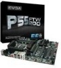
EVGA 141-LF-E658-KR - P55 FTW 200 Motherboard Manual
 |
UPC - 843368011727
View all EVGA 141-LF-E658-KR manuals
Add to My Manuals
Save this manual to your list of manuals |
EVGA 141-LF-E658-KR manual content summary:
- EVGA 141-LF-E658-KR | User Guide - Page 1
User's Guide EVGA P55 FTW 200 Motherboard 1 - EVGA 141-LF-E658-KR | User Guide - Page 2
2 - EVGA 141-LF-E658-KR | User Guide - Page 3
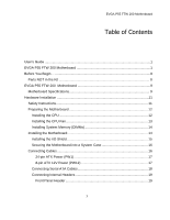
EVGA P55 FTW 200 Motherboard Table of Contents User's Guide ...1 EVGA P55 FTW 200 Motherboard 1 Before You Begin...8 Parts NOT in the Kit 8 EVGA P55 FTW 200 Motherboard 9 Motherboard Specifications 9 Hardware Installation 11 Safety Instructions 11 Preparing the Motherboard 12 Installing the - EVGA 141-LF-E658-KR | User Guide - Page 4
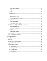
and LED Status Indicators 25 Post Port Debug LED 25 LED Status Indicators 25 Jumper Settings ...26 PCIE Disable Jumper 26 Voltage Measure Point 27 EVGA Control Panel V2 (ECP 28 Configuring the BIOS 32 Enter BIOS Setup 33 Main Menu...33 Standard BIOS Features Menu 36 System Time / System - EVGA 141-LF-E658-KR | User Guide - Page 5
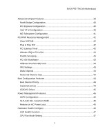
EVGA P55 FTW 200 Motherboard Advanced Chipset Features 39 North Bridge Configuration 40 PCI Express Configuration 40 Intel VT-d Configuration 40 ME Subsystem Configuration 41 PCI/PNP Resource Management 42 Clear NVRAM...42 Plug & Play O/S 42 PCI Latency Timer 42 Allocate IRQ to - EVGA 141-LF-E658-KR | User Guide - Page 6
Frequency/Voltage Control Menu 47 Memory Configure 48 CPU Configuration 48 Installing Drivers and Software 49 Windows XP/Vista/7 Driver Installation 49 Appendix A. POST Codes for the EVGA P55 FTW 200 Motherboard 50 6 - EVGA 141-LF-E658-KR | User Guide - Page 7
EVGA P55 FTW 200 Motherboard List of Figures Figure 1. PW1 Motherboard Connector 17 Figure 2. CMOS Setup Utility Main Menu 34 Figure 3. Standard BIOS Features Menu 36 Figure 4. Advanced BIOS - EVGA 141-LF-E658-KR | User Guide - Page 8
necessary to install and connect your new EVGA P55 FTW 200 Motherboard. However, it does not contain the following items that must be purchased separately to make the motherboard functional. Intel Socket 1156 Processor DDR3 System Memory Socket 1156 or Socket 775 Cooling fan PCI Express or - EVGA 141-LF-E658-KR | User Guide - Page 9
EVGA P55 FTW 200 Motherboard Motherboard Specifications Size ATX form factor of 12 inch x 9.6 inch Processor support Intel Socket 1156 CPU's Operating systems: Supports Windows XP 32bit/64bit, Windows Vista 32bit/64bit, and Windows 7 32bit/64bit Intel P55 Express Chipset System Memory - EVGA 141-LF-E658-KR | User Guide - Page 10
header) with a rate transmission of 400 Mbps Onboard Audio Realtek High-Definition audio Supports 8-channel audio Supports Jack-Sensing function Green Function Supports ACPI (Advanced Configuration and Power Interface) Supports S0 (normal), S1 (power on suspend), S3 (suspend to RAM), S4 (Suspend - EVGA 141-LF-E658-KR | User Guide - Page 11
This section will guide you through the installation of the motherboard. The topics covered in this section are: Preparing the motherboard Installing the CPU Installing the CPU fan Installing the memory Installing the motherboard Connecting cables Safety Instructions To reduce the - EVGA 141-LF-E658-KR | User Guide - Page 12
lever back and the load plate will automatically lift. There is a protective socket cover within the CPU socket to protect the socket when there is no CPU installed. Remove the protective socket cover from the CPU Socket in a straight up motion. Note: It is a good idea to save the cover so that - EVGA 141-LF-E658-KR | User Guide - Page 13
the load plate so it is resting on the CPU. Pull back the socket lever again to ensure the load plate tip engages under the shoulder screw cap many different fan types that can be used with this motherboard. Follow the instruction that came with you fan assembly. Be sure that the fan orientation is - EVGA 141-LF-E658-KR | User Guide - Page 14
Installing System Memory (DIMMs) Your new motherboard has four 240-pin slots for DDR3 memory. These slots support 256 MB, 512 MB, 1GB, 2GB, 4GB DDR3 technologies. There must be at least one memory bank populated to ensure normal operation. Use the following - EVGA 141-LF-E658-KR | User Guide - Page 15
the connections prior to this step or to secure the motherboard and then make all the connections. It is normally easier to secure the motherboard first. Use the following procedure to install the I/O shield and secure the motherboard into the chassis. Installing the I/O Shield The motherboard kit - EVGA 141-LF-E658-KR | User Guide - Page 16
the connectors to the I/O shield. 4. Ensure that the fan assembly is aligned with the chassis vents according to the fan assembly instruction. 5. Secure the motherboard with a recommended minimum of nine (9) screws. Connecting Cables This section takes you through all the necessary connections on - EVGA 141-LF-E658-KR | User Guide - Page 17
24-pin ATX Power (PW1) PW1 is the main power supply connector located along the edge of the board next to the DIMM slots. Make sure that the power supply cable and pins are properly aligned with the connector on the motherboard. Firmly plug the power supply cable into the connector and make sure it - EVGA 141-LF-E658-KR | User Guide - Page 18
the Serial ATA II device to the motherboard. These connectors support the thin Serial ATA II cables for primary storage devices. designed to be angled to not interfere with any expansions cards. These connection points support RAID 0, RAID 1, and RAID 10 configurations. SATA 4 (bottom) SATA 2 - EVGA 141-LF-E658-KR | User Guide - Page 19
Connecting Internal Headers Front Panel Header The front panel header on this motherboard is one connector used to connect the following four cables. (see Table 2 for pin definitions): PWRLED Attach the front panel power LED cable to these two pins of the connector. The Power LED indicates the - EVGA 141-LF-E658-KR | User Guide - Page 20
IEEE1394a (Firewire) This motherboard has one IEEE 1394a onboard header. Alternatively, you can also connect this to your system case (if applicable). 1. Secure the bracket to either the front or rear panel of the system case (not all system cases are equipped with the front panel option). Connect - EVGA 141-LF-E658-KR | User Guide - Page 21
USB Headers This motherboard contains seven (7) USB 2.0 ports that are exposed on the rear panel of the chassis (Figure 2). The motherboard also contains three (3) 10pin internal header connectors onboard that can be used to connect an optional external bracket containing up to six (6) USB 2.0 ports - EVGA 141-LF-E658-KR | User Guide - Page 22
HD audio standard and provides two kinds of audio output choices: the Front Audio, the Rear Audio. The front Audio supports re-tasking function. Table 5. Front Audio Connector Connector Front Audio Connector 10 9 8 7 6 5 4 3 2 1 Pin Signal 1 PORT1_L 2 AUD_GND 3 PORT1_R 4 PRECENCE_J - EVGA 141-LF-E658-KR | User Guide - Page 23
slot that is designed to accommodate PCIe x1 cards, such as an EVGA Killer Xeno Network Card or Sound Card. The x1 slot provides 250 Cards and PCI Express x1 and x4 devices. The design of this motherboard supports multiple Graphic Card technology. When installing a PCI Express Graphic Card, be sure - EVGA 141-LF-E658-KR | User Guide - Page 24
These onboard buttons allow you to easily turn on/off the system. These buttons allow for easy debugging and testing of the system during troubleshooting situations. The POWER button with LED indicates the system's status. When the system is powered on, the LED remains a solid red. The RESET - EVGA 141-LF-E658-KR | User Guide - Page 25
Status Indicators Post Port Debug LED Provides two-digit POST codes to show why the system may be failing to boot. It is useful during troubleshooting situations. This Debug LED will also display current CPU temperatures after the system has fully booted into the Operating System. Debug LED with CPU - EVGA 141-LF-E658-KR | User Guide - Page 26
Jumper Settings PCIE Disable Jumper For the ease of troubleshooting Multiple Video Cards, or testing individual Video Card's Overclocking, EVGA has implemented 3 Jumpers you can use to disable individual PCIE slots. You don't need to remove any of your video cards but simply disable the - EVGA 141-LF-E658-KR | User Guide - Page 27
Voltage Measure Point The motherboard is equipped with eight voltage measure point pad. You can use a voltmeter to measure the voltage you want to know. CPU Vcore voltage CPU VTT voltage Memory voltage P55 chipset voltage CPU PLL voltage Ground 27 - EVGA 141-LF-E658-KR | User Guide - Page 28
V2 (ECP) For the convenience of users, EVGA has bundled an easy to Access Control Panel: To use the ECP, simply hook up the black ECP Cable to the motherboard at the ECP header location. (See visual guide) The other end of the Cable should be connected to the ECP as shown - EVGA 141-LF-E658-KR | User Guide - Page 29
If you wish to access the PCIE Disable Function via the ECP, please follow these instructions: Locate the PCIE Disable Jumpers (see visual guide) Remove the 3 jumpers. Connect the PCIE Cable with the Red wires occupying the left most pins: It doesn't matter which end of the PCIE Cable - EVGA 141-LF-E658-KR | User Guide - Page 30
The Red wires should be occupying the pins on the top row. Now, access the Disable/Enable Function at the front of the Control Panel: From Right to Left, PCIE Slots 1,2,3. When Jumper is in top position, PCIE slot is enabled. When in bottom position PCIE slot is disabled. Above shows example of PCIE - EVGA 141-LF-E658-KR | User Guide - Page 31
will go down to what you have set. The 2 buttons are exactly the same in function each. Vtt Booster The far right button on the EVGA ECP increases the VTT voltage by +0.1v. 31 - EVGA 141-LF-E658-KR | User Guide - Page 32
Configuring the BIOS This section discusses how to change the system settings through the BIOS Setup menus. Descriptions of the BIOS parameters are also provided. This section includes the following information: Enter BIOS Setup Main Menu Standard BIOS Features Advanced BIOS Features - EVGA 141-LF-E658-KR | User Guide - Page 33
Configuring the BIOS Enter BIOS Setup The BIOS is the communication bridge between hardware and software. Correctly setting the BIOS parameters is critical to maintain optimal system performance and stability. Use the following procedure to verify/change BIOS settings. 3. Power on the computer. 4. - EVGA 141-LF-E658-KR | User Guide - Page 34
CMOS Setup Utility - Copyright (C) 1985-2005, American Megatrends Standard BIOS Features Advanced BIOS Features Advanced Chipset Features PCI/PNP Resource Management Boot Configuration Features Power Management Features Hardware Health Configure Frequency/Voltage Control Load - EVGA 141-LF-E658-KR | User Guide - Page 35
Configuring the BIOS Frequency/Voltage Control Use this menu to optimize system performance and configure clocks, voltages, memory timings, and more. Load Optimal Defaults Load default system settings. Discard Changes Use this command to abandon all setting changes and exit setup. Save - EVGA 141-LF-E658-KR | User Guide - Page 36
1985-2005, American Megatrends Standard BIOS Features System Overview AMIBIOS Version :08.00.16 Build Date:07/16/10 ID :1E658A19 Processor Intel(R) Core(TM) CPU Speed :2666MHz Count :1 750 @ 2.67GHz Help Item Use [ENTER] , [TAB] Or [SHIFT-TAB] to select a field. Use [+] or [-] to - EVGA 141-LF-E658-KR | User Guide - Page 37
Configuring the BIOS System Time / System Date Using the arrow keys, position the cursor over the month, day, and year. Use the + and - keys to scroll through dates and times. Note that the weekday (Sun through Sat) cannot be changed. This field changes to correspond to the date you enter. Note - EVGA 141-LF-E658-KR | User Guide - Page 38
CMOS Setup Utility - Copyright (C) 1985-2005, American Megatrends Advanced BIOS Features Advanced Settings WARNING: Setting wrong values in below sections may cause system to malfunction. Help Item Main Level IDE Configuration [Press Enter] Boot Settings Configuration[Press Enter] - EVGA 141-LF-E658-KR | User Guide - Page 39
more. USB Configuration This option menu allows you to enable Legacy USB support, force USB 1.1 mode and more. Advanced Chipset Features Select Advanced Chipset [Press Enter] PCI Express Configuration [Press Enter] Intel VT-d [Disabled] HD Audio Controller [Enabled] IEEE1394 [Enabled - EVGA 141-LF-E658-KR | User Guide - Page 40
such as Payload size. It is not recommended to adjust these settings. Intel VT-d Configuration This option menu allows you to enable, or disable, are using an external Network Controller, such as an EVGA Killer Xeno card. LAN2 Controller This function allows you to enable or - EVGA 141-LF-E658-KR | User Guide - Page 41
Configuring the BIOS controller. It is recommended to leave this enabled, unless you are using an external Network Controller, such as an EVGA Killer Xeno card. ESATA Controller This function allows you to enable or disable the SATA interface. PE1 Slot This function allows you to enable or - EVGA 141-LF-E658-KR | User Guide - Page 42
PCI/PNP Resource Management Select PCI/PNP Resource Management from the CMOS Setup Utility menu and press Enter to display the advanced settings. CMOS Setup Utility - Copyright (C) 1985-2005, American Megatrends PCI/PNP Resource Management Advanced PCI/PnP Settings WARNING: Setting wrong values - EVGA 141-LF-E658-KR | User Guide - Page 43
BusMaster This function allows the BIOS to use PCI BusMastering for reading or writing to IDE drives. OffBoard PCI/ISA IDE Card This function allows manual override of PCI/ISA external cards. A setting of [Auto] works for most devices. IRQ Settings The various IRQ settings allows you to reserve IRQ - EVGA 141-LF-E658-KR | User Guide - Page 44
Boot Configuration Features Select Boot Configuration Features from the CMOS Setup Utility menu and press Enter to display the settings. CMOS Setup Utility - Copyright (C) 1985-2005, American Megatrends Boot Configuration Features Boot Device Priority Hard Disk Drives CD/DVD Drives [Press - EVGA 141-LF-E658-KR | User Guide - Page 45
Configuring the BIOS CD/DVD Drives This option menu allows you specification of the CD/DVD boot priority sequence. Power Management Features Select Power Management Features from the CMOS Setup Utility menu and press Enter to display the settings. CMOS Setup Utility - Copyright (C) 1985-2005, - EVGA 141-LF-E658-KR | User Guide - Page 46
ACPI Configuration This menu will allow adjustment of Advanced ACPI configurations. SLP_S4# Min. Assertion Width This function allows adjustment of the SLP assertion width. Restore on AC Power Loss This menu allows adjustment of the AC Power Loss parameters. Hardware Health Configure Select - EVGA 141-LF-E658-KR | User Guide - Page 47
Frequency Setting [Auto] PCIE Frequency Setting [100] QPI Frequency Selection [Auto] MCH Strap [Auto] Main Level Extreme Cooling [Disabled] EVGA VDroop Control [With VDroop] Current CPU VCore : 1.20000V Bootup CPU VCore [Auto] Eventual CPU VCore [Auto] Current Dimm Voltage : 1.50V - EVGA 141-LF-E658-KR | User Guide - Page 48
Figure 10. Frequency/Voltage Control Memory Configure This menu will allow the configuration of advanced memory timings, including memory frequency and memory timings. CPU Configuration This menu will allow the configuration of advanced CPU settings, such as Virtualization Technology, CPU SpeedStep, - EVGA 141-LF-E658-KR | User Guide - Page 49
with the EVGA P55 FTW 200 Motherboard contains the following software and drivers: Chipset Drivers Audio drivers LAN Drivers RAID Drivers EVGA E-LEET Overclocking Utility Adobe Acrobat Reader User's Manual Windows XP/Vista/7 Driver Installation 1. Insert the Intel P55 installation CD - EVGA 141-LF-E658-KR | User Guide - Page 50
Appendix A. POST Codes for the EVGA P55 FTW 200 Motherboard This section provides the AMI POST Codes (Table 6) for the EVGA P55 FTW 200 Motherboard during system boot up. The POST Codes are displayed on the Debug LED readout located directly onboard the motherboard. This Debug LED will also - EVGA 141-LF-E658-KR | User Guide - Page 51
Configuring the BIOS Code 0B 0C 0E 13 20 24 2A 2C 2E 31 33 37 38 39 3A 3B 3C 40 52 60 75 78 7C 84 85 87 8C 8D 8E Description Detect Mouse Detect Keyboard Test input devices Early POST initialization of chipset registers Relocate System Management interrupt vector Uncompress and initialize BIOS - EVGA 141-LF-E658-KR | User Guide - Page 52
for Int 19 boot End of POST initialization Save system context for ACPI Pass control to OS Show CPU Temp (if enabled) EVGA Glossary of Terms ACPI - Advanced Configuration and Power Interface AFR - Alternate Frame Rendering APIC - Advanced Programmable Interrupt Controller BIOS - Basic Input Output - EVGA 141-LF-E658-KR | User Guide - Page 53
DRAM - Dynamic random access memory DVD - Digital Versatile Disc DVI - Digital Video Interface FDC - Floppy Disk Controller FSB - Front Side Bus FTW - For The Win! GHz - Gigahertz GPU - Graphics Processing Unit HDD - Hard Disk Drive HDMI - High-Definition Multimedia Interface HDR - High Dynamic - EVGA 141-LF-E658-KR | User Guide - Page 54
NB - Northbridge NCQ - Native Command Queuing NIC - Network Interface Card NTFS - New Technology File System OEM - Original Equipment Manufacturer PATA - Parallel Advanced Technology Attachment PCB - Printed Circuit Board PCI - Peripheral Component Interconnect PCIe - Peripheral Component
-
 1
1 -
 2
2 -
 3
3 -
 4
4 -
 5
5 -
 6
6 -
 7
7 -
8
-
9
-
10
-
11
-
12
-
13
-
14
-
15
-
16
-
17
-
18
-
19
-
20
-
21
-
22
-
23
-
24
-
25
-
26
-
27
-
28
-
29
-
30
-
31
-
32
-
33
-
34
-
35
-
36
-
37
-
38
-
39
-
40
-
41
-
42
-
43
-
44
-
45
-
46
-
47
-
48
-
49
-
50
-
51
-
52
-
53
-
54
 |
 |

1
User
’s
Guide
EVGA P55 FTW 200 Motherboard