Edimax ES-5500G Quick Install Guide
Edimax ES-5500G Manual
 |
View all Edimax ES-5500G manuals
Add to My Manuals
Save this manual to your list of manuals |
Edimax ES-5500G manual content summary:
- Edimax ES-5500G | Quick Install Guide - Page 1
cost of all necessary servicing repak and any inddental from those shown in this Manual. The software and specifications are sers. The ES-5500G/ES-5800G supports dynamic detection of cable length and • One Gigabit Switch • Quick installation Guide • 5V 1A (ES.550DG)/ 12V problem pandit CO- CE FC
-
 1
1
 |
 |

NEIVIO0.1010
PEOPLE
TOSETMER
5
/
8
Ports
Desktop
Gigabit
Ethernet
Switches
ES
-5500G
/
ES
-5800G
Quick
Installation
Guide
Version
1.0
/
September,
2009
Thank
you
for
purchasing
Edimax
gigabit
sedan.
This
high
cost
-efficiency
swath
complies
with
10/100/1000
-Base
-TX
standards
is
the
best
Stoic*
for
Small
office
/
Flame
office
sers.
The
ES-5500G/ES-5800G
supports
dynamic
detection
of
cable
length
and
dynamic
adjustment
of
power
required
for
the
detected
cable
imp
for
power
seines
.
Th
e
switch
also
can
detect
link
status
for
each
port:.
When
the
port
is
Idle,
the
ES-55(10G/ES-5800G
wel
reduce
power
usage
for
the
pod.
Easy
Metall
procedures
allows
any
computer
users
to
setup
a
network
environment
In
very
short
time
.
Product
Package
The
package
contains
the
following
components:
•
One
Gigabit
Switch
•
Quick
installation
Guide
•
5V
1A
(ES.550DG)/
12V
1A
(ES
-5800G)
•
Accessories
kit
•
am
item
is
missing
or
damaged,
please
contact
your
local
re
-sellers
for
orrice.
Feature
•
Complies
with
the
IEEE
802.3,
IEEE
802.3u
and
IEEE
802.3ab
standards.
•
Smart
Green
Ethemet
technology
to
reduce
power
consumption
35%-50%.
•
Provides
Store
and
Forward
architecture,
full
wire
speed
fltedng
and
forwarding
rates.
•
Supports
Auto-MDINDI-X.
full/hall
duplex
modes
and
auto.negotiation.
•
Supports
fl
ow
control:
back
pressure
for
half
-duplex,
IEEE
802.3x
for
full-cluplex
mode.
•
Supports
Jumbo
Frame
in
all
speeds
mode
(10/100/1000Mbps).
•
Automatic
source
address
learning
and
aging,
°dens.
front
-panel
diagnostic
LEDs.
2
m7!iP!w5.
Copyright0by
Edimax
Technology
Co,
LTD.
all
rights
reserved.
No
part
Syria
pubtication
rary
be
reproduced,
transmitted,
honseribed,
stored
e
a
retrieval
system,
or
translated
into
any
language
a
computer
temp.'e.
In
any
born
Or
by
any
means,
etedoonk,
mxbaNpl,
meta.,
oat.,
cheml.,
mama
or
Mena,
without
the
Mandato
permission
of
Ns
co
mpany
This
company
makes
no
re
presentations
or
warrantee,
either
expressed
crimpled,
with
resod°
the
co.nd
hereof
and
specifically
disclaims
any
warmtim,
marchturlability
a
fi
tness
for
any
particular
purpose.
Any
software
deealbed
in
this
manual
is
sold
or
licensed
'as
is
.
Should
the
programs
prove
defective
folkwing
their
purchase,
the
buyer
(end
not
ar
ia
company.
its
distributor,
or
its
dealer)
assumes
the
entire
cost
of
all
necessary
servicing
repak
and
any
inddental
co
nsequential
damages
resubng
from
any
detest
in
the
solbsere.
Further,
this
company
reserves
the
right
to
re
ds
this
publication
and
to
make
changes
from
ti
me
to
ti
me
in
the
conted
hereof
withan
obligation
to
notify
any
pawn
Sauce
re
vi
sion
or
enemas.
The
product
you
have
purehased
and
the
setup
screen
may
appear
slightly
different
from
those
shown
in
this
Manual.
The
software
and
specifications
are
subject
to
change
without
not..
Please
visit
our
web
site
wormed...am
for
the
update.
All
dghb
reserved
including
all
brand
and
product
names
me.ned
in
the
man.
ere.demerks
anaor
registered
trademarks
of
their
respective
holders.
Federal
Communication
Commission
interference
Statement
This
equipment
.
been
tested
and
found
to
comply
wail
the
limits
for
a
Cress
B
dlpal
dm.,
pursuant
to
Part
15
of
FCC
Rules
Th
ese
limits
are
designed
to
provide
reasonable
nation
against
hannful
Interference
Ina
residential
Installation.
This
equipment
generates,
we,
and
can
radiate
radio
frequency
energy
and,
if
not
in.!ted
and
used
in
awardersce
nth
the
.8..08,
may
cause
harmful
interference
to
ratio
communication.
However,
there
is
no
guarantee
that
interference
will
not
occur
in
a
particular
installation.
If
the
equipment
doe
cause
harmful
interference
b
radio
or
television
reception,
which
can
be
determined
by
turning
the
equipment
off
and
on,
the
user
is
encouraged
to
try
to
correct
the
i.rfanince
by
one
or
more
of
ma
following
measures:
1.
Reorient
or
.ssate
the
meek',
antenna.
2.
Increase
the
eeparatlon
between
th
e
eaten..
and
receiver.
S.
Connect
the
equipment
into
an
cutlet
co
a
deed
different
from
that
toyMich
the
receiver
is
connected.
S.
Consult
the
dealer
°ran
operienced
radio
technician
for
help.
FCC
Caution
This
device
end
fi
e
antenna
must
re
d
be
co
-located
or
operating
In
co
njunction
WM
any
other
a.nna
or
tr
anamitter.T.
device
complies
with
Pad
15
of
the
FCC
Rule.
Ops.on
is
subject
to
the
following
boo
conditions:
(1)
this
device
may
fl
atware
harmful
Interference,
and
(2)
this
device
m.
meant
any
'Madelyn.
received
including
interferers:4,MR
may
care
undeei.
opera..
My
changes
a
.
modifications
.
expressly
approved
by
the
party
responsible
for
compliance
could
void
the
e.ority
to
operate
equipment.
CE
Mink
Warning.
This
is
a
Cleo
A
pmduct
Ina
domestic
environment.
the
pmduct
may
cause
radio
int.,
in
ankh
nee
the
user
may
be
required
to
take
adequate
measures.
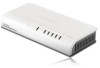
Front
Panels
Connector.
WI%
ES
-5500C
I
1
EB-SBOOG
3
Fast
Ethernet
Switch
LED
Panel
PWR
Lit
The
switch
is
powered
on
(Power)
Green
Off
The
switch
b
powered
on
LNK/ACT
Lit
Avalid
link
is
established
Flash
Data
packets
received
(Link/Activity)
Green
Off
No
link
is
established
1.
Operating
Environment
This
switching
hub
must
be
installed
and
operated
within
the
limits
of
specified
operating
temperature
0
,
40°C
(32°-104°F)
and humidity
10%
-
90%
(non
-condensing).
.
Do
not
place
objects
on
top
of
the
unit.
.
Do
not
obstruct
any
vents
at
the
sides
of
the
uniL
.
Do
not
position
the
unit
near
any
healing
source
such
as
heater,
radiator,
or
direct
exposure
to
sun.
Prevent
entering
of
water
and
moisture
into
the
unit.
If
necessary,
use
dehumidifier
to
reduce
humidity.
2.
Connecting
to
network
devisee
The
RJ-45
ports
on
the
switch
support
Auto-MDIAADI-X
function
which
allows
using
straight
-through
or
cross
-over
type
cables
to
connect
this
switch
to
workstation
or
hub.
Connect
one
end
ti
the
network
cable
to
the
RJ-45
port
on
the
rear
panel,
and
connect
the
other
end
of
the
network
cable
to
the
Redo
port
on
the
nehvork
device.
Follow
the
same
procedure
to
connect
all
the
RJ-45
ports
of
the
switch.
The
UTP
network
cables
must
comply
with
EINTIA
588
specifications
and
Category
5
standard
for
100Mbps
data
transmission.
Maximum
length:
wing
LITP
cable,
between
the
snitch
and
connected
device
is
100
meters
(3000).
Once
the
nehvork
cable
is
connected
to
both
ends
and
the
attached
network
device
is
powered
on,
the
green
LNK/ACT
LED
should
be
lit.
4
3.
Connecting
the
power
Conned
the
power
adapter
to
the
power
connector
on
the
rear
panel
of
the
unit;
the
green
Power
LED
on
the
front
panel
should
be
lit
Moulds
Shooting
1.
Power
LED
is
not
lit
.
Check
Bas
power
cord
is
properly
connected
to
the
e:demal
power
adapter
and
the
power
outlet.
Make
sure
the
DC
power
jack
is
fi
rmly
plugged
into
the
power
socket
of
the
switch.
2.
Link/Activity
le
not
If
when
conned
to
device
.
Check
the
power
switch
cl
aw
nehvork
device
attached
to
are
switch;
make
sure
it
is
timed
ON.
.
Check
the
network
cable;
make
sum
it
is
properly
conneded
to
the
switch
and
the
nebsiork
device.
.
Check
the
network
cable;
make
sure
the
IITP
cables
co
mply
with
EIAMA
588
and
Category
5
seeder:Mon.
Ill Cont.
your
dealer
If
problem
pandit
CO-
CE
FC