Electrolux E30EW75PPS Wiring Diagram English
Electrolux E30EW75PPS Manual
 |
View all Electrolux E30EW75PPS manuals
Add to My Manuals
Save this manual to your list of manuals |
Electrolux E30EW75PPS manual content summary:
- Electrolux E30EW75PPS | Wiring Diagram English - Page 1
satisfactory manner. 2. Before servicing or moving an appliance, Door Open Door Closed Bread Proof X Rack Supports not installed Conv. P11 X* X X Door EOC- display board. For trouble-shooting purposes, it is possible above approximately 2500 RPM. If problem persists replace both the fan+ - Electrolux E30EW75PPS | Wiring Diagram English - Page 2
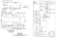
USER INTERFACE BOARD P9 OUT CONNECTS TO J5 P10 SWITCH 1 OUT P6 PROGRAMMING HEADER P18 MEAT PROBE P13 AUX OUT CONNECTS TO J6 P2 LIN COMM 1 CONNECTS TO TRIAC P8 BACKLIGHT POWER CONNECTS TO POWER SUPPLY RELAY BOARD P8 P10 P12 1 P1 TEMP PROBE P7 EXT LEDS/KEY, RING LIGHTS, PANEL BACKLIGHT CONTROL/ - Electrolux E30EW75PPS | Wiring Diagram English - Page 3
faire de manière satisfaisante et sécuritaire. 2. Avant de procéder au service d'entretien ou de déplacer tout appareil ménager, débranchez le cordon d' ère X Porte ouverte X Porte fermée Pâte à pain X X Support grille pas installé Sur panneau d'affichage Interr. porte P10-3 / P10 - Electrolux E30EW75PPS | Wiring Diagram English - Page 4
PLAQUETTE D'INTERFACE DE UTILISATEUR P9 POUR RACCORDER J5 P12 COMMUTATEUR 1 SORTIE P6 PROGRAMMATION TÊTE P13 AUX SORTIE CONNECTE SUR J6 P2 LIN COMM 1 CONNECTE SUR TRIAC P8 ECLAIRAGE ALIMENTATION PERMET DE CONNECTER ALIMENTATION CARTE RELAIS P8 P10 P12 L1 INFÉRIEUR 1 P18 SONDE THERMIQUE P1
-
 1
1 -
 2
2 -
 3
3 -
 4
4
 |
 |
IMPORTANT
DO NOT REMOVE THIS BAG
OR DESTROY THE CONTENTS
WIRING DIAGRAMS AND SERVICE
INFORMATION
ENCLOSED
REPLACE CONTENTS IN BAG
p/n 807436906 REV A (1607)
ELECTRONIC OVEN CONTROL (EOC) FAULT CODE DESCRIPTIONS
Note: Generally speaking “F1X” implies a control failure, “F3X” an oven probe problem, and “F9X” a latch motor problem.
Failure Code/ Condition/Cause
Suggested Corrective Action
F10
Control has sensed a potential runaway oven
condition. Control may have shorted relay, RTD
sensor probe may have a gone bad.
Check RTD sensor probe and replace if necessary. If oven is overheating, disconnect power. If oven continues to overheat when
power is reapplied, replace relay board and/or display board.
F11
Shorted Key: a key has been detected as
pressed for a long period and will be considered
a shorted key alarm and will terminate all
oven activity.
Press any key to clear the error.
If fault returns, replace the keyboard (touch panel).
If the problem persists, replace the display board.
F13
Control's internal checksum may have
become corrupted.
Press any key to clear the error.
Disconnect power, wait 30 seconds and reapply power. If fault returns upon power-up, replace display board.
F14
Misconnected keyboard cable
Verify connection between display board and touch panel (2 ribbon cables). Make sure the cables are well connected at both ends.
If the cables are good, replace the touch panel.
If the problem persists, replace the display board.
F15
Controller self check failed.
Verify if relay board receives 120VAC between J4 pin 1 and 3.
Verify the wiring between J2 on the relay board and P16 on the display board.
If wiring and 120VAC supply is good replace the display board.
If problem persists replace the relay board.
F23
The controller failed to communicate with the
oven lights control board.
Verify wiring between P2 on the display board and P2 on the oven lights control board.
If wiring is good, replace oven lights board.
If the problem persists, replace the display board.
F30
Open RTD sensor probe/ wiring problem.
Note: EOC may initially display an "F10", thinking a
runaway condition exists.
Check wiring in probe circuit for possible open condition.
Check RTD resistance at room temperature (compare to probe resistance chart). If resistance does not match the chart, replace the RTD sensor probe.
F31
Shorted RTD sensor probe / wiring problem.
Let the oven cool down and restart the function.
If the problem persists, replace the display board.
Note: F30 or F31 is displayed when oven is in active mode or an attempt to enter an active mode is made.
F43
The cooling fan speed, as read by the
tachometer input of the EOC-display board,
is abnormally too slow.
Determine first if the problem appears to be caused by a cooling fan not turning or turning slowly or by a problem with the sensing of
the fan speed. Start a Bake and check during the first 15 seconds if the fan is turning (should feel air flowing through the vent above
the upper oven door).
If the fan does not appear to be turning or turn slowly check the 120VAC at the fan. If 120VAC is present at the fan motor but the fan
does not turn replace the fan motor. If 120VAC is not present at the fan motor when a Bake is started check the connection to the
relay board (J3 pin 7) and Neutral: is there 120VAC on J3 pin 7? Does it reach the fan motor? Is the other terminal of the fan motor
connected to Neutral? If the harness or relay board are faulty replace them.
If the fan appears to be normally turning but an F43 error code is generated, it means there is a problem with the reading of the fan
speed sensor. Make sure the connection of the fan speed sensor is properly made (refer to wiring diagram), between the sensor on
the fan and the EOC- display board.
For trouble-shooting purposes, it is possible to enter a test mode that will indicate on the display the reading of the fan speed in RPM:
to enter the test mode, power-up the unit and within 30 seconds press and hold the upper oven Bake and Broil keys for 3 seconds
(until you see all segments in the screen illuminated). Once in the test mode, pressing the upper oven Light key once will display the
fan speed in RPM. In normal client mode the F43 error is generated for a fan speed below approximately 700 RPM.
F44
The cooling fan speed, as read by the
tachometer input of the EOC- display board,
is abnormally too fast.
Inspect the cooling fan. Does it appear to be turning normally (air flow, noise)? Verify the fan blade is well assembled.
Verify there is nothing blocking the air flow of the fan (that could make the fan turn faster).
Check the 120VAC voltage on the fan. A voltage higher than 120VAC + 10% could make it go too fast.
Make sure the connection of the fan speed sensor is properly made (refer to wiring diagram), between the sensor on the fan and the
EOC- display board.
For trouble-shooting purposes, it is possible to enter a test mode that will indicate on the display the reading of the fan speed in RPM: to enter
the test mode, power-up the unit and within 30 seconds press and hold the upper oven Bake and Broil keys for 3 seconds (until you see all
segments in the screen illuminated). Once in the test mode, pressing the upper oven Light key once will display the fan speed in RPM. In normal
client mode the F44 error is generated for a fan speed above approximately 2500 RPM.
If problem persists replace both the fan+sensor assembly and the EOC- display board.
F90
Door motor mechanism failure.
Press any key to clear the error.
I
f it does not eliminate the problem, turn off power for 30 seconds, then turn on power.
Check wiring of Lock Motor, Lock Switch and Door Switch circuits.
Unplug the lock motor from the board and apply power (L1) directly to the Lock Motor. If the motor does not rotate, replace Lock Motor Assembly.
Check Lock Switch for proper operation (do they open and close, check with ohmmeter). The Lock Motor may be powered as in above
step to open and close Lock Switch. If the Lock Switch is defective, replace Motor Lock Assembly.
If all above steps fail to correct situation, replace the display board and/or the relay board in the event of a motor that does not rotate.
If all the above steps fail to correct the situation, replace the display board in the event of a motor that rotates endlessly.
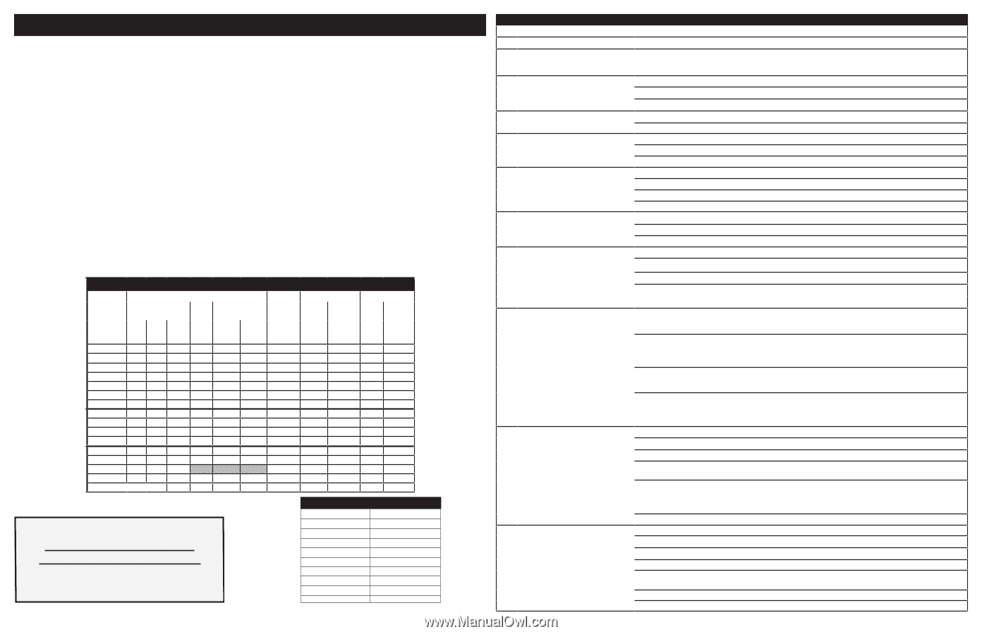
SINGLE WALL OVEN CIRCUIT ANALYSIS MATRIX
On Relay Board
On Oven
lights
control
board
On Display Board
On Relay Board
ELEMENTS
Door
Motor
J3-5
Convection Fan
Door
Switch
P10-3/
P10-5
Rack
Sense
Switch
P10-2/
P10-5
DLB
L2 out
P1
Cooling
Fan
J3-7
Bake
P9
Broil
P7
Conv.
P11
Low
speed
J3-8
High
speed
J3-4
Light
P2-1
Bake
X
X
X*
X*
X
X
Keep Warm
X
X
X
Broil
X
X
X
Conv. Bake
X
X
X
X**
X
X
X
Conv. Roast
X
X
X
X
X
X
Conv. Broil
X
X
X
X
Clean
X
X
X
X
Locking
X
Locked
Unlocking
X
Unlocked
Light
X
Door Open
X
Door Closed
X
Bread Proof
X
X
X
X
Rack Supports not installed
X
Resistance (ohms)
1000 ± 4.0
1091 ± 5.3
1453 ± 8.9
1654 ± 10.8
1852 ± 13.5
2047 ± 15.8
2237 ± 18.5
2697 ± 24.4
Open circuit/infinite resistance
RTD SCALE
Temperature °F (°C)
32 ± 1.9 (0 ± 1.0)
75 ± 2.5 (24 ± 1.3)
250 ± 4.4 (121 ± 2.4)
350 ± 5.4 (177 ± 3.0)
450 ± 6.9 (232 ± 3.8)
550 ± 8.2 (288 ± 4.5)
650 ± 9.6 (343 ± 5.3)
900 ± 13.6 (482 ±7.5)
Probe circuit to case ground
SERVICE DATA SHEET
Appliance with 63x Electronic Oven Control
NOTICE:
This service data sheet is intended for use by persons having electrical and me-
chanical training and a level of knowledge of these subjects generally considered acceptable
in the appliance repair trade. The manufacturer cannot be responsible, nor assume any
liability, for injury or damage of any kind arising from the use of this data sheet.
IMPORTANT NOTE:
This unit includes an EOC (electronic oven control). This board is not
field-repairable.
SAFE SERVICING PRACTICES
To avoid the possibility of personal injury and/or property damage, it is important that safe
servicing practices be observed. The following are some, but not all, examples of safe
practices.
1.
Do not attempt a product repair if you have any doubts as to your ability to complete it
in a safe and satisfactory manner.
2.
Before servicing or moving an appliance, remove power cord from electric outlet, trip
circuit breaker to Off, or remove fuse.
3.
Never interfere with the proper installation of any safety device.
4.
Use only replacement parts specified for this appliance. Substitutions may not comply
with safety standards set for home appliances.
5.
Grounding: The standard color coding for safety ground wires is green or green with
yellow stripes. Ground leads are not to be used as current carrying conductors. It is
extremely important that the service technician reestablish all safety grounds prior to
completion of service. Failure to do so will create a potential hazard.
6.
Prior to returning the product to service, ensure that:
•
All electric connections are correct and secure.
•
All electrical leads are properly dressed and secured away from sharp edges,
high-temperature components, and moving parts.
•
All uninsulated electrical terminals, connectors, heaters, etc. are adequately
spaced away from all metal parts and panels.
•
All safety grounds (both internal and external) are correctly and securely reas-
sembled.
•
All panels are properly and securely reassembled.
OVEN CALIBRATION
Set the electronic oven control for normal baking at 350°F. Allow oven to preheat to set
temperature. Obtain an average oven temperature after a minimum of five cycles. Press the
STOP
key to end the Bake mode.
TEMPERATURE ADJUSTMENT
1.
While in a non-cooking mode, press and hold the
Bake
key for 6 seconds.
2.
The current calibration offset (temperature adjustment) should appear in the tempera-
ture display.
3.
Use the number keys (0-9) to enter the desired amount of adjustments (up to 35°F).
4.
Press the
Self Clean
key to change the sign of the adjustment to a (-), if necessary. A
positive adjustment will not display a sign.
5.
Once the desired adjustment (-35° to 35° F) has been entered, press the
Start
key to
accept the change or the
Cancel
key to reject the change.
Note:
Changing calibration affects all baking modes. The adjustments made will not change
the self-cleaning temperature.
2-SPEED COOLING FAN
The EOC controls the speed of the cooling fan. The cooling fan is activated at low speed
during any cooking function and will remain on until the oven is cooled down. The high speed
is activated during the broil (with open door) and during clean cycles only when the tempera-
ture is above apporximately 575°F/302°C.