Electrolux EI30GS55JS Installation Instructions (All Languages)
Electrolux EI30GS55JS Manual
 |
View all Electrolux EI30GS55JS manuals
Add to My Manuals
Save this manual to your list of manuals |
Electrolux EI30GS55JS manual content summary:
- Electrolux EI30GS55JS | Installation Instructions (All Languages) - Page 1
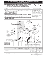
30" GAS SLIDE-IN RANGE INSTALLATION INSTRUCTIONS (Models with Sealed Top Burners) INSTALLATION AND SERVICE MUST BE PERFORMED BY A QUALIFIED INSTALLER. IMPORTANT: SAVE FOR LOCAL ELECTRICAL INSPECTOR'S USE. READ AND SAVE THESE INSTRUCTIONS FOR FUTURE REFERENCE. If the information in this manual is - Electrolux EI30GS55JS | Installation Instructions (All Languages) - Page 2
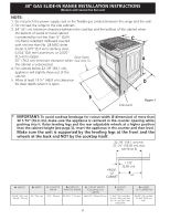
30" GAS SLIDE-IN RANGE INSTALLATION INSTRUCTIONS (Models with Sealed Top Burners) NOTE: 1. Do not pinch the power supply cord or the flexible gas conduit between the range and the wall. 2. Do not seal the range to the side cabinets. 3. 24" (61 cm) minimum clearance between the cooktop and the - Electrolux EI30GS55JS | Installation Instructions (All Languages) - Page 3
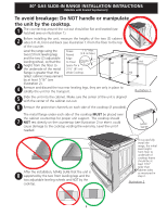
30" GAS SLIDE-IN RANGE INSTALLATION INSTRUCTIONS (Models with Sealed Top Burners) To avoid breakage: Do NOT handle or manipulate the unit by the cooktop. 1 The counter-top around the cut-out should be flat and leveled (see hatched area on illustration 1). 2 Before installing the unit, measure the - Electrolux EI30GS55JS | Installation Instructions (All Languages) - Page 4
operation. FOR MODELS WITH SELF-CLEAN FEATURE: • Remove oven racks, broiler pan, food and other utensils before self-cleaning the oven. Wipe up excess spillage. Follow the precleaning instructions in the Use and Care Guide. • Unlike the standard gas range, THIS COOKTOP IS NOT REMOVABLE. Do not - Electrolux EI30GS55JS | Installation Instructions (All Languages) - Page 5
30" GAS SLIDE-IN RANGE INSTALLATION INSTRUCTIONS (Models with Sealed Top Burners) 1 Cabinet Construction To eliminate the risk of cabinet burns and fire, do not have cabinet storage space above the range. If there is cabinet storage space above range, reduce risk by installing a range hood that - Electrolux EI30GS55JS | Installation Instructions (All Languages) - Page 6
30" GAS SLIDE-IN RANGE INSTALLATION INSTRUCTIONS (Models with Sealed Top Burners) 3 Seal the openings Seal any openings in the wall behind the range and in the floor under the range after gas supply line is installed. 4 Connect the range to the gas supply Important: Remove all packing material and - Electrolux EI30GS55JS | Installation Instructions (All Languages) - Page 7
30" GAS SLIDE-IN RANGE INSTALLATION INSTRUCTIONS (Models with Sealed Top Burners) The conversion must be performed by a qualified service technician in accordance with the manufacturer's instructions and all local codes and requirements. Failure to follow these instructions could result in serious - Electrolux EI30GS55JS | Installation Instructions (All Languages) - Page 8
30" GAS SLIDE-IN RANGE INSTALLATION INSTRUCTIONS (Models with Sealed Top Burners) 8.10 Position range in front leg base and turn clockwise to lower or counterclockwise to raise. b.Remove the rear legs using a wrench on the leg base and turn counterclockwise until the legs are removed from the unit - Electrolux EI30GS55JS | Installation Instructions (All Languages) - Page 9
30" GAS SLIDE-IN RANGE INSTALLATION INSTRUCTIONS (Models with Sealed Top Burners) 10 Check Operation Refer to the Use and Care Guide packaged with the range for operating instructions and for care and cleaning of your range. Do not touch the elements or burners. They may be hot enough to cause - Electrolux EI30GS55JS | Installation Instructions (All Languages) - Page 10
30" GAS SLIDE-IN RANGE INSTALLATION INSTRUCTIONS (Models with Sealed Top Burners) 10.4 Adjust the "low" setting for regular surface burner valves (Figure 11) Be careful when performing this operation. a. Push in and turn control to LITE until burner ignites. b. Quickly turn knob to LOWEST POSITION - Electrolux EI30GS55JS | Installation Instructions (All Languages) - Page 11
30" GAS SLIDE-IN RANGE INSTALLATION INSTRUCTIONS (Models with Sealed Top Burners) 10.6.2 Air Shutter-Oven Burner The approximate oven burner flame length is 1 inch (distinct inner cone of blue flame). To determine if the oven burner flame is proper, remove the oven bottom and burner baffle and set - Electrolux EI30GS55JS | Installation Instructions (All Languages) - Page 12
30" GAS SLIDE-IN RANGE INSTALLATION INSTRUCTIONS (Models with Sealed Top Burners) 11 Anti-Tip Brackets Installation Instructions To reduce the risk of tipping of the range, the range must be secured to the floor by properly installed anti-tip bracket and screws packed with the range. These parts - Electrolux EI30GS55JS | Installation Instructions (All Languages) - Page 13
aparato se debe instalar con un largo conector flexible de gas de tres (3) pies/36 pulgadas. Una válvula manual de gas de tipo manija de forma de "T" se debe instalar en la línea del suministro de gas de este aparato. PARED 30" Mín. (76,2 cm Mín.) La superficie debe estar plana y nivelada (area - Electrolux EI30GS55JS | Installation Instructions (All Languages) - Page 14
INSTALACIÓN DE COCINAS DE GAS DE 30" (Modelos con quemadores sellados) NOTAS: 1. No pellizque el cordón eléctrico o el conducto flexible de gas entre la estufa y la soportada por las patas adelante y por las ruedas en la parte de atrás y NO por la cubierta superior sobre la encimera. 22 7/8" (58,1 cm) - Electrolux EI30GS55JS | Installation Instructions (All Languages) - Page 15
INSTRUCCIONES DE INSTALACIÓN DE COCINAS DE GAS DE 30" (Modelos con quemadores sellados) Para evitar fractura para dejar espacio 3 ruedas ajustables, de manera que la altura del para una unidad con suelo a la parte de abajo del un dimensión de 31 ½" (81 cm). reborde de metal sea de al H2 H1 - Electrolux EI30GS55JS | Installation Instructions (All Languages) - Page 16
GAS DE 30" (Modelos con quemadores sellados) Notas importantes para el Instalador 1. Lea todas las instrucciones contenidas en este manual sobre la temperatura ambiental sin provocar encogimiento, deformación o decoloración. No instale la estufa sobre una alfombra al menos que coloque una plancha de - Electrolux EI30GS55JS | Installation Instructions (All Languages) - Page 17
piso y 3" (7.6 cm) del centro de la linea. Zona 2 - Por medio del piso (~2" X 24") - La linea de gas puede salir del suelo con 12" (30.5 cm) del centro de la linea con respecto al la pared de atrás. Puede remover la pieza de metal en "L" localizada atrás del aparato. No existe problema alguno al - Electrolux EI30GS55JS | Installation Instructions (All Languages) - Page 18
estufa antes de conectar el gas y la fuente eléctrica. Para evitar fugas, aplique sellador de tuberías en todas las partes roscadas machos (exterior) de la por resultado una fuga de gas y un fuego o una explosión. Valvula de FLUJO DEL GAS Regulador cierre Unión manual Unión de presión Abierto - Electrolux EI30GS55JS | Installation Instructions (All Languages) - Page 19
apague la válvula de cierre manual de gas. Asegúrese de que la 30" (76.2 cm) de espacio entre ellas. Asegúrese que estos estén verticales y alineados antes de instalar la plancha de cocinar. Lije el borde del mostrador para obtener las 31 1/2 (80 cm)" en la parte superior del mostrador. 8.3 Instale - Electrolux EI30GS55JS | Installation Instructions (All Languages) - Page 20
GAS DE 30" (Modelos con quemadores sellados) 8.6 Quite y deshágase de las dos patas ajustables traseras, solo sirven para sostener la unidad durante el transporte. 8.7 Instale de la abertura del armario. 8.11 Asegúrese que la parte de abajo de la cubierta libre la superficie del mostrador o - Electrolux EI30GS55JS | Installation Instructions (All Languages) - Page 21
INSTRUCCIONES DE INSTALACIÓN DE COCINAS DE GAS DE 30" (Modelos con quemadores sellados) 10 Comprobación del Funcionamiento Consulte el Manual del Usuario incluido con la estufa para instrucciones de operación y instrucciones para el cuidado y limpieza de su estufa. No toque los elementos o - Electrolux EI30GS55JS | Installation Instructions (All Languages) - Page 22
INSTRUCCIONES DE INSTALACIÓN DE COCINAS DE GAS DE 30" (Modelos con quemadores sellados) 10.5 Adjust the "LOW" Setting of the Dual Burner Surface Valve (Figure 11) Note: On the dual valve the low setting of each portion should be adjusted individually. a. Push in and turn control to LITE until the - Electrolux EI30GS55JS | Installation Instructions (All Languages) - Page 23
COCINAS DE GAS DE 30" (Modelos fondo del horno, retire los tornillos de ajuste del horno en la parte posterior del fondo del horno. Jale hacia arriba, desenganche el frente al Servicio Lea la sección Evite Llamadas de Servicio en su Manual del Usuario. Esto le podrá ahorrar tiempo y gastos. Esta - Electrolux EI30GS55JS | Installation Instructions (All Languages) - Page 24
INSTRUCCIONES DE INSTALACIÓN DE COCINAS DE GAS DE 30" (Modelos con quemadores sellados) 11 Instrucciones de instalación . Si no hay pared posterior, dibujar otra línea en el piso que corresponda a la parte posterior de la cocina. 2. Desplegar el molde de papel y colocarlo alisado sobre el piso con - Electrolux EI30GS55JS | Installation Instructions (All Languages) - Page 25
ÈRE ENCASTRABLE DE 30" À GAZ (Modèles avec brûleurs fermés) UN INSTALLATEUR QUALIFIÉ DOIT EFFECTUER L'INSTALLATION ET LE SERVICE. IMPORTANT: CONSERVEZ CES INSTRUCTIONS POUR LES INSPECTEURS LOCAUX. LISEZ CES INSTRUCTIONS ET CONSERVEZ‑LES POUR RÉFÉRENCES ULTÉRIEURES. Si les instructions de ce manuel - Electrolux EI30GS55JS | Installation Instructions (All Languages) - Page 26
INSTRUCTIONS D'INSTALLATION POUR CUISINIÈRE ENCASTRABLE DE 30" À GAZ (Modèles avec brûleurs fermés) 34), insérez l'appareil dans le comptoir et ensuite nivelez- le. Assurez-vous que l'appareil est bien supporté par les pattes et roulettes de nivellement et non par la table de cuisson. 22 7/8" (58,1 - Electrolux EI30GS55JS | Installation Instructions (All Languages) - Page 27
INSTRUCTIONS D'INSTALLATION POUR CUISINIÈRE ENCASTRABLE DE 30" À GAZ (Modèles avec brûleurs fermés) Pour é côté de la table de cuisson DOIT reposer sur le comptoir pour que l'appareil soit bien supporté. 7 La table de cuisson ne doit PAS toucher directement le comptoir (voir illustration 2), sinon - Electrolux EI30GS55JS | Installation Instructions (All Languages) - Page 28
instructions avec le guide de l'utilisateur pour référence ultérieure. INSTRUCTIONS DE SÉCURITÉ IMPORTANTES Cette cuisinière doit être install faire un cycle autonettoyant du four. Essuyez tous les renversements excessifs. Suivez les instructions pour le pré-nettoyage dans le Guide de l'utilisateur - Electrolux EI30GS55JS | Installation Instructions (All Languages) - Page 29
INSTRUCTIONS D'INSTALLATION POUR CUISINIÈRE ENCASTRABLE DE 30" À GAZ (Modèles avec brûleurs fermés) 1 Construction de l'armoire Pour éliminer les risques de brûlures ou de feu, en étendant le bras au‑dessus des surfaces de cuisson chaudes, évitez d'installer des armoires au‑dessus de ces dernières. - Electrolux EI30GS55JS | Installation Instructions (All Languages) - Page 30
INSTRUCTIONS D'INSTALLATION POUR CUISINIÈRE ENCASTRABLE DE 30" À GAZ (Modèles avec brûleurs fermés) 3 Scellez les ouvertures Scellez toutes les ouvertures dans le mur à l'arrière de la cuisinière ainsi que celles dans le plancher sous l'appareil une fois que la ligne de gaz est install tre installé - Electrolux EI30GS55JS | Installation Instructions (All Languages) - Page 31
30" À GAZ (Modèles avec brûleurs fermés) PROPANE». Suivez les instructions d'installation se trouvant dans l'enveloppe. Un installateur qualifié doit effectuer la conversion conformément aux instructions de l'appareil en vue d'en faire le service ou pour faire du nettoyage Coupez l'alimentation é - Electrolux EI30GS55JS | Installation Instructions (All Languages) - Page 32
INSTRUCTIONS D'INSTALLATION POUR CUISINIÈRE ENCASTRABLE DE 30" À GAZ (Modèles avec brûleurs fermés) 8.8 Afin d'obtenir une installation plancher qui supporte la cuisinière service. Installation de panneaux latéraux Vous pouvez commander un nécessaire pour panneaux latéraux dans un centre de service - Electrolux EI30GS55JS | Installation Instructions (All Languages) - Page 33
INSTRUCTIONS D'INSTALLATION POUR CUISINIÈRE ENCASTRABLE DE 30" À GAZ (Modèles avec brûleurs fermés) 10 Vérification du Fonctionnement Référez‑vous au Guide de l'utilisateur inclus avec la cuisinière pour les directives de fonctionnement et pour l'entretien et le nettoyage de votre cuisinière. Ne - Electrolux EI30GS55JS | Installation Instructions (All Languages) - Page 34
INSTRUCTIONS D'INSTALLATION POUR CUISINIÈRE ENCASTRABLE DE 30" À GAZ (Modèles avec brûleurs fermés) 10.4 Réglage de la position "LOW" des La flamme du brûleur s'éteint entre 20 et 30 secondes après que l'allumeur eut été coupé. Ce cycle continuera pour maintenir toute température réglée jusqu'à - Electrolux EI30GS55JS | Installation Instructions (All Languages) - Page 35
INSTRUCTIONS D'INSTALLATION POUR CUISINIÈRE ENCASTRABLE DE 30" À GAZ (Modèles avec brûleurs fermés) de l'expédition. Avant d'appeler le service d'entretien Révisez la liste de vérifications préventives et les instructions d'opération dans votre Guide de l'utilisateur. Vous sauverez probablement du - Electrolux EI30GS55JS | Installation Instructions (All Languages) - Page 36
POUR CUISINIÈRE ENCASTRABLE DE 30" À GAZ (Modèles avec brûleurs fermés) 11 Instructions d'installation du support anti‑bascule Pour réduire le risque de basculement de la cuisinière, protégez-la en installant les vis et le support anti‑bascule fournis avec la cuisinière. Ils sont situés dans - Electrolux EI30GS55JS | Installation Instructions (All Languages) - Page 37
NOTES - NOTAS 37 - Electrolux EI30GS55JS | Installation Instructions (All Languages) - Page 38
NOTES - NOTAS 38 - Electrolux EI30GS55JS | Installation Instructions (All Languages) - Page 39
WIRING DIAGRAM - Diagrama de la instalación alámbrica - SCHÉMA DE CÂBLAGE - Electrolux EI30GS55JS | Installation Instructions (All Languages) - Page 40
WIRING DIAGRAM - Diagrama de la instalación alámbrica - SCHÉMA DE CÂBLAGE
-
 1
1 -
 2
2 -
 3
3 -
 4
4 -
 5
5 -
 6
6 -
 7
7 -
8
-
9
-
10
-
11
-
12
-
13
-
14
-
15
-
16
-
17
-
18
-
19
-
20
-
21
-
22
-
23
-
24
-
25
-
26
-
27
-
28
-
29
-
30
-
31
-
32
-
33
-
34
-
35
-
36
-
37
-
38
-
39
-
40
 |
 |
30" GAS SLIDE-IN RANGE INSTALLATION INSTRUCTIONS
(Models with Sealed Top Burners)
E
E
P/N 318201686 (1010) Rev. B
English – pages 1-12; Español – páginas 13-24;
Français - pages 25-36; Notes - pages 37-38;
Wiring Diagrams - pages 39-40
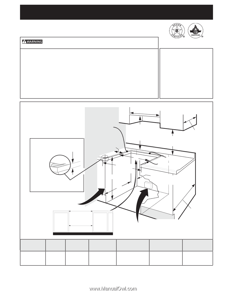
If the information in this manual is not followed exactly, a fire
or explosion may result causing property damage, personal injury or death.
FOR YOUR SAFETY:
— Do not store or use gasoline or other flammable vapors and liquids in the
vicinity of this or any other appliance.
— WHAT TO DO IF YOU SMELL GAS:
• Do not try to light any appliance.
• Do not touch any electrical switch; do not use any phone in your building.
• Immediately call your gas supplier from a neighbor's phone. Follow the
gas supplier's instructions.
• If you cannot reach your gas supplier, call the fire department.
— Installation and service must be performed by a qualified installer, service
agency or the gas supplier.
INSTALLATION AND SERVICE MUST BE PERFORMED BY A QUALIFIED INSTALLER.
IMPORTANT: SAVE FOR LOCAL ELECTRICAL INSPECTOR'S USE.
READ AND SAVE THESE INSTRUCTIONS FOR FUTURE REFERENCE.
NOTE: Wiring diagram for these appliances are enclosed in this booklet.
Printed in United States
Appliances Installed in the
state of Massachusetts:
This Appliance can only be installed
in the state of Massachusetts by a
Massachusetts licensed plumber or
gasfitter.
This appliance must be installed
with a three (3) foot / 36 in. long
flexible gas connector.
A"T" handle type manual gas
valve must be installed in the gas
supply line to this appliance.
Refer to your serial plate for
applicable agency certification
1/2” min.
3/8” min.
1/2” min.
WALL
5" Min.
(12,7 cm Min.)
From Wall Both Sides
30" Min.
(76,2 cm Min.)
18" Min.
(45,7 cm) Min.
Approx. 1 7/8"
(4,8 cm)
Grounded Junction Box or Wall Outlet Should Be
Located 8" to 17" (20,3 cm to 43,2 cm) From Right
Cabinet and 2" to 4" (5,1 cm to 10,2 cm) From Floor.
Locate Cabinet Doors 1" (2,5 cm)
Min. from Cutout Opening.
F
G
E
31 1/2"
(81 cm)
Exact
13"
(33 cm)
24" Min.
(61 cm Min.)
Shave
Raised
Edge
to Clear
Space
for a 31½"
(80 cm) Wide
Cooktop.
1 ½" Max.
(3,8 cm Max.)
30" Min.
(76,2 cm) Min.
(see Note 3)
These surfaces should be flat
& leveled (hatched area).
A
. HEIGHT
B
.
WIDTH
C.
COOKTOP
WIDTH
D
.
DEPTH TO
FRONT OF RANGE
E
.
CUTOUT WIDTH*
(Countertop and
Cabinet)
F
.
CUTOUT
DEPTH
G
.
HEIGHT
OF COUNTERTOP
35 5/8" (90.5 cm)
- 36 5/8" (93 cm)
30" (76,2 cm)
31½" (80 cm)
28 5/16" (71,9 cm)
30±1/16" (76,2±0,15 cm)
21 3/4" (55,2 cm) Min.
22 1/8" (56,2 cm) Max
24" (61 cm) Min. with
backguard
36 5/8" (93 cm) Max.
35 3/4" (90.8 cm)
Min.
IMPORTANT:
Cabinet and
countertop width
should match the
cutout width.