Electrolux EW27MC65JW Installation Instructions (All Languages)
Electrolux EW27MC65JW Manual
 |
View all Electrolux EW27MC65JW manuals
Add to My Manuals
Save this manual to your list of manuals |
Electrolux EW27MC65JW manual content summary:
- Electrolux EW27MC65JW | Installation Instructions (All Languages) - Page 1
of supporting 275 pounds (125 kg) for 27" models and 350 pounds (159 kg) for 30" models. 2. Allow at least 21" (53.3 cm) clearance in front of oven for door depth when it is open. 3. Dimension G (cutout depth) is critical to the proper installation of the built-in oven. If the oven decorative trim - Electrolux EW27MC65JW | Installation Instructions (All Languages) - Page 2
Consumer Keep these instructions with your Owner's Guide for future reference. Do not discard oven removal tools found in the literature bag. IMPORTANT SAFETY INSTRUCTIONS • Be sure your combination oven is installed and grounded properly by a qualified installer or service technician. • This wall - Electrolux EW27MC65JW | Installation Instructions (All Languages) - Page 3
MICROWAVE/ WALL OVEN COMBINATION INSTALLATION INSTRUCTIONS Electrical Shock Hazard • Electrical ground is a new branch circuit installation (1996 NEC), mobile home, recreational vehicles, where local code do not permit grounding trough the neutral (white) wire or in Canada, disconnect the white and - Electrolux EW27MC65JW | Installation Instructions (All Languages) - Page 4
trim of the oven and visible when the door is opened. When ordering parts for or making inquires about your oven, always be sure to include the model and serial numbers and a lot number or letter from the serial plate on your oven. 4. Cabinet Installation disengage the hinge supports. Keep pulling - Electrolux EW27MC65JW | Installation Instructions (All Languages) - Page 5
supports (see owner's guide for further instructions). 4 Find the 2 mounting screws included in the literature package. 5 Insert the unit into the cabinet opening. Slide unit inward leaving 1½" (3.8 cm) clearance between the unit and front of cabinet (see Figure 7). 7 Install now the bottom trim - Electrolux EW27MC65JW | Installation Instructions (All Languages) - Page 6
IMPORTANT NOTE A cooling fan inside the upper rear part above the oven (some models) provides cooling of the oven electrical and electronic components Before You Call for Service Read the "Before You Call for Service Checklist" and the "Operating Instructions" in your Use and Care Guide. It may save - Electrolux EW27MC65JW | Installation Instructions (All Languages) - Page 7
LE MODÈLE COMBINÉ FOUR À ENCASTRER/FOUR À MICRO-ONDES L'INSTALLATION ET L'ENTRETIEN DOIVENT ÊTRE EFFECTUÉS PAR UN INSTALLATEUR QUALIFIÉ. IMPORTANT : CONSERVEZ POUR L'INSPECTEUR D'ÉLECTRICITÉ LOCAL. LISEZ ET CONSERVEZ CES INSTRUCTIONS POUR RÉFÉRENCES ULTÉRIEURES. POUR VOTRE SÉCURITÉ : N'entreposez - Electrolux EW27MC65JW | Installation Instructions (All Languages) - Page 8
POUR LE MODÈLE COMBINÉ FOUR À ENCASTRER/FOUR À MICRO-ONDES Notes importantes pour l'installateur 1. Lisez toutes les instructions contenues dans ce feuillet avant l'installation du four encastré. 2. Enlevez tout le matériel d'emballage du four avant de procéder au raccordement électrique - Electrolux EW27MC65JW | Installation Instructions (All Languages) - Page 9
INSTRUCTIONS D'INSTALLATION POUR LE MODÈLE COMBINÉ FOUR À ENCASTRER/FOUR À MICRO-ONDES Risque de locaux n'autorisent pas la connexion du conducteur de mise à la terre du châssis au neutre ou au Canada, débranchez les fils blanc et vert des autres et utilisez le fil de mise à la terre pour mettre - Electrolux EW27MC65JW | Installation Instructions (All Languages) - Page 10
de l'appareil et ainsi faciliter sa manipulation et son installation. Suivre les instructions suivantes pour enlever la porte du four: 1. Ouvrez , soulevez légèrement la porte et tirez-la vers vous pour dégager les supports de charnières. Continuez à tirer la porte vers vous en faisant pivoter - Electrolux EW27MC65JW | Installation Instructions (All Languages) - Page 11
INSTRUCTIONS D'INSTALLATION POUR LE MODÈLE COMBINÉ FOUR À ENCASTRER/FOUR À MICRO-ONDES 3 Retirez tous l'emballage et les accessoires des fours et retirez aussi les grilles et les supports de grilles du four inférieur (voir manuel d'utilisation pour plus de détails). 4 Localisez les vis de fixation - Electrolux EW27MC65JW | Installation Instructions (All Languages) - Page 12
INSTRUCTIONS D'INSTALLATION POUR LE MODÈLE COMBINÉ FOUR À ENCASTRER/FOUR À MICRO-ONDES 9 lorsque l'on ouvre la porte du four. Avant d'appeler le service d'entretien Réviser la liste de vérifications préventives et les instructions d'opération dans votre Manuel d'utilisation et d'entretien. Vous
-
 1
1 -
 2
2 -
 3
3 -
 4
4 -
 5
5 -
 6
6 -
 7
7 -
8
-
9
-
10
-
11
-
12
 |
 |

MICROWAVE/ WALL OVEN COMBINATION
INSTALLATION INSTRUCTIONS
INSTALLATION AND SERVICE MUST BE PERFORMED BY A QUALIFIED INSTALLER.
IMPORTANT: SAVE FOR LOCAL ELECTRICAL INSPECTOR'S USE.
READ AND SAVE THESE INSTRUCTIONS FOR FUTURE REFERENCE.
FOR YOUR SAFETY: Do not store or use gasoline or other
flammable vapors and liquids in the vicinity of this or any other appliance.
P/N 318201539 (1007) Rev. D
English – pages 1-6
Français -pages 6-12
All dimensions are in inches (cm).
Printed in United States
Canada
United States
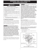
Figure 1
Do not remove spacers (if equipped) on the side walls and/or on the back of the built-in
oven. These spacers center the oven in the space provided.
The oven must be centered to prevent excess
heat buildup that may result in heat damage or fire.
NOTES:
1.
Base must be capable of supporting 275 pounds (125 kg)
for 27" models and 350 pounds (159 kg) for 30" models.
2.
Allow at least 21" (53.3 cm) clearance in front of oven
for door depth when it is open.
3.
Dimension
G
(cutout depth) is critical to the proper
installation of the built-in oven. If the oven decorative
trim does not butt against the cabinet, or if noise is heard
on convection models, verify dimension
G
to assure it is
according to the required dimension.
**4.
For a cutout height
(H)
between
44"
(111.8cm)
and
44
5
/
8
"
(113.3 cm) add a 2" (5 cm) wide wood
shim of appropriate height to each side of the
opening under the appliance side rails. Lifting the
unit will allow you to hide the cutout openings
showing above the unit. The bottom trim of the unit
will hide the shims at the bottom.
**5.
For a cutout height
(H)
between
44
5
/
8
"
(113.3 cm)
and
46
3
/
8
"
(117.8 cm) you can order a larger bottom
trim through your Service Center.
Door Open
(see note 2)
Hole for
Cable
Electrical
Junction Box
2" (5 cm) Wide Wood Spacer
if Needed (see note 4)
Spacer
*
Suggested distance from floor is 11½" (29.2 cm).
Minimum required distance is 4 ½" (11.4 cm).
*
PRODUCT DIMENSIONS
MODEL
A
B
C
D
27" (68.6 cm) Wall Oven
27 (68.6)
45
1
/
4
(114.9)
24
5
/
8
(62.5)
24½ (62.2)
30" (76.2 cm) Wall Oven
30 (76.2)
45
1
/
4
(114.9)
28¼ (71.8)
24½ (62.2)
CUTOUT DIMENSIONS AND CABINET WIDTH
F
G (Min.)
H. Standard Height
(**Others, see notes 4 & 5)
I
MODEL
Min.
Max.
Min.
Max
.
27" (68.6 cm) Wall Oven
25
5
/
8
(65.1)
25
7
/
8
(65.7)
23½ (59.7)
43
7
/
8
(111.3)
44 (111.8)
27
1
/
8
(68.9) Min
30" (76.2 cm) Wall Oven
28½ (72.4)
29 (73.7)
23½ (59.7)
43
7
/
8
(111.3)
44 (111.8)
30
1
/
8
(76.5) Min
Your new wall oven has been designed to fit a limited variety of cutout sizes to make the job of installing easier.
The first step of your installation should be to measure your current cutout dimensions and compare them to the
cutout dimensions chart below for your model. You may find little or no cabinet work being necessary.