Electrolux EW30EF65GS Installation Instructions (All Languages)
Electrolux EW30EF65GS - 30 Inch Electric Range Manual
 |
UPC - 012505544514
View all Electrolux EW30EF65GS manuals
Add to My Manuals
Save this manual to your list of manuals |
Electrolux EW30EF65GS manual content summary:
- Electrolux EW30EF65GS | Installation Instructions (All Languages) - Page 1
Guide. Note: Changing calibration affects normal Bake mode. The adjustments made will not change the Self-Cleaning cycle temperature. ELECTRONIC OVEN CONTROL (EOC) FAULT CODE DESCRIPTIONS Symptom Likely failure condition/cause Suggested corrective action Control Beeping No Error Codes Display - Electrolux EW30EF65GS | Installation Instructions (All Languages) - Page 2
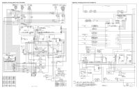
GENERAL TROUBLESHOOTING DIAGRAM GENERAL TROUBLESHOOTING SCHEMATIC
-
 1
1 -
 2
2
 |
 |
NOTICE
-
This service data sheet is intended for use by persons having
electrical and mechanical training and a level of knowledge of these
subjects generally considered acceptable in the appliance repair trade.
The manufacturer cannot be responsible, nor assume any liability for
injury or damage of any kind arising from the use of this data sheet.
SAFE SERVICING PRACTICES
To avoid the possibility of personal injury and/or property damage, it is
important that safe servicing practices be observed.
The following are
examples, but without limitation, of such practices.
1.
Before servicing or moving an appliance remove power cord from electrical
outlet, trip circuit breaker to OFF, or remove fuse.
2.
Never interfere with the proper installation of any safety device.
3.
GROUNDING:
The standard color coding for safety ground wires is
p/n 316904409
(0905)
SERVICE DATA SHEET
-
Electric Ranges with ES 630A Electronic Oven Control
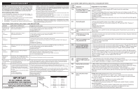
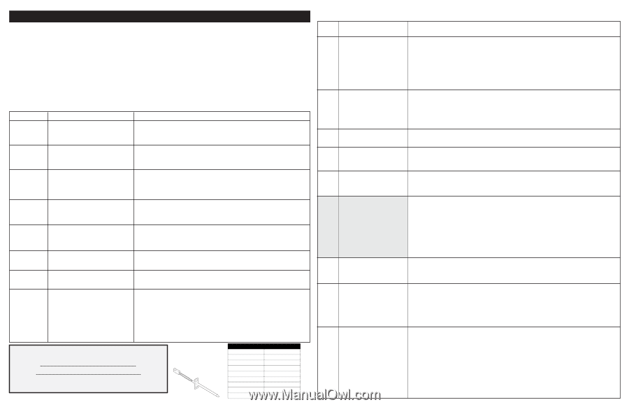
ELECTRONIC OVEN CONTROL (EOC) FAULT CODE DESCRIPTIONS
IMPORTANT
DO NOT REMOVE THIS BAG
OR DESTROY THE CONTENTS
WIRING DIAGRAMS AND SERVICE INFORMATION
ENCLOSED
REPLACE CONTENTS IN BAG
Resistance
Temperature
Detector
F10
F11
F13
F14
F15
F20
F23
F25
F30
F31
F90
Runaway temperature.
Oven heats when no cook
cycle is programmed.
Shorted keypad.
Internal software error in
EOC.
TST Display tail missing
or not connected.
Signal loss between oven
relay board & EOC.
Communication failure
between EOC & ESEC.
(Electric models only)
Communication failure
between VSC board and
EOC.
Open probe connection.
Shorted Probe
connection
Door lock motor latch
failure
1. Check RTD Sensor Probe using the RTD scale found in the tech sheet.
Replace if defective.
2. If oven is overheating dsiconnect power from the range and unplug connector P1 from
power supply board. Reapply power to the range. If oven continues to heat when the power
is reapplied, replace the oven relay board.
3. Replace the EOC.
NOTE: Severe overheating may require the entire oven to be replaced should damage be
extensive.
1. Reset power supply to range to see if failure code will clear.
2 Test ribbon harness and connectors between the TST panel and EOC. Replace if
defective.
3. Replace the TST panel.
4. Replace the EOC.
Disconnect power, wait 30 seconds and reapply power. If fault returns upon power-up,
replace EOC.
1.Test ribbon harness and connections between TST panel and EOC. Replace if defective
2. Replace the TST panel.
3. Replace the EOC.
1. Test the harness and connections from EOC connector P16 to oven relay board J2.
2. Replace the oven relay board.
3. Replace the EOC.
1. Test wiring harness and connections between EOC connector P2 and ESEC 30 UIB P9.
2. Test wiring harness and connections between ESEC 30 UIB and ESEC 20 relay board.
3. Test wiring harness and connections between PS board 2 (P2) and ESEC 30 UIB
connector P7
4. Test for approximately 9 volts DC output from PS board 2 at ESEC 30 UIB connector
P7, pins 1 & 5. If output voltage is incorrect test incoming power supply to PS board 2 at
harness connector P1 pins 1 & 4.
If incoming power is correct (120 VAC) replace PS
board 2. If output voltage is correct replace ESEC 30 UIB
5. Replace EOC.
1.
Check harness and connections between VSC board and EOC.
2.
Test for approximately 5 volts DC to VSC board at P6 connector pins 1 & 6. If voltage is
correct replace VSC board. If voltage is incorrect replace EOC.
1. (F30 or F31) Check resistance at room temperature & compare to RTD Sensor
resistance chart. If resistance does not match the RTD chart replace RTD Sensor Probe.
Check Sensor wiring harness between EOC & Sensor Probe connector.
2. (F30 or F31) Check resistance at room temperature, if less than 500 ohms, replace
RTD Sensor Probe. Check for shorted Sensor Probe harness between EOC & Probe
connector.
If latch motor does not run
when clean cycle is selected:
1. Check to see if latch motor coil is open. If open, replace latch motor assembly.
2. Test for 120 volts to the terminals of the latch motor. If voltage is correct and motor
does not run replace
latch motor assembly. If voltage is not correct replace EOC.
If latch motor runs
when clean cycle is selected:
1. Check the wiring harness between EOC & latch motor switch. Repair or replace
harness as needed.
2. Test operation of the switch contacts. Replace latch motor assembly if defective.
3. Check for binding of the latch cam, latch motor rod & latch motor cam.
4. If all situations above do not solve problem, replace EOC.
Fault
Code
Symptom
Suggested Corrective Action
GREEN
or
GREEN WITH YELLOW STRIPES
.
Ground leads are not to be used as
current carrying conductors.
It is extremely important that the service technician
reestablish all safety grounds prior to completion of service.
Failure to do so
will create a potential safety hazard.
4.
Prior to returning the product to service, ensure that:
• All electric connections are correct and secure.
• All electrical leads are properly dressed and secured away from sharp edges, high-
temperature components, and moving parts.
• All uninsulated electrical terminals, connectors, heaters, etc. are adequately
spaced away from all metal parts and panels.
• All safety grounds (both internal and external) are correctly and securely reassembled.
Oven Calibration/
Temperature adjustment - See Use & Care Guide.
Note: Changing calibration affects normal Bake mode. The adjustments made will not
change the Self-Cleaning cycle temperature.
Control Beeping
No Error Codes
Display
“ E “
In Displays
“E
11”
In Displays
“ E
14 “
In Displays
“ E
15 “
In Displays
“HE” and no
Element
Power
“HE” in display
even when surface
is cold.
Surface
Element hot,
but no “HE”
appears
1. Check ribbon connection J3 connection on the ESEC 30 UIB to J5 on TST panel.
2. Test continuity of ribbon harness. Replace if defective.
3. Replace ESEC 30 UIB.
4. Replace TST panel.
1. Check ribbon connection J2 connection on the ESEC30 UIB to J4 on TST panel.
2. Test continuity of ribbon harness. Replace if defective.
3. Replace ESEC 30 UIB.
4. Replace TST panel.
1. Reset power supply to range to see if failure code will clear.
2 Test ribbon harness and connectors between the TST panel and ESEC 30 UIB. Replace if
defective.
3. Replace the TST panel.
4. Replace the ESEC 30 UIB.
1. Check ribbon connection J4 connection on the ESEC 30 UIB to J3 on TST panel.
2. Test continuity of ribbon harness. Replace if defective.
3. Replace ESEC 30 UIB.
4. Replace TST panel.
1. Check harness and connections between connector P6 of ESEC30 UIB
to connector J2 of
ESEC relay board. Repair or replace harness as needed.
2. If connection and harness are good. then replace ESEC relay board.
3. If error remains ESEC30 UIB.
1.Correct wiring of that element and its hot surface limiter.
1. With power disconnected, check continuity of hot surface limiter contacts (1b-2b) at that
element’s terminalblock.contacts are closed even when the surface is cold replace element.
2. If hot surface limiter contacts (1B-2B) are open replace power board.
1. Check the wire harness connector and seat properly to Relay Board J4 connector.
2. Check surface harness for correct wiring from each element’s hot surface limiter - correct wiring
or replace harness if necessary.
3.Turn on all elements to Hi. Wait 3 minutes to ensure all surfaces are hot. Check continuity
of limiter switch circuit for each element. If circuit is open replace that surface element. NOTE:
Limiter contacts can be tested through the harness on Relay Board connector J4
4.Check the wire harness and connectors from ESEC 30 UIB P5 to Relay Board Connector J5.
Replace harness if defective.
5. Replace Relay Board.
6. Replace ESEC 30 UIB.
RTD SCALE
Temperature (°F)
Resistance (ohms)
32 ± 1.9
1000 ± 4.0
75 ± 2.5
1091 ± 5.3
250 ± 4.4
1453 ± 8.9
350 ± 5.4
1654 ± 10.8
450 ± 6.9
1852 ± 13.5
550 ± 8.2
2047 ± 15.8
650 ± 9.6
2237 ± 18.5
900 ± 13.6
2697 ± 24.4
ESEC key display ribbon cable is
disconnected or defective
ESEC key display ribbon cable is
disconnected or defective.
Shorted keypad.
ESEC key read ribbon cable is disconnected
or defective.
Signal loss between ESEC 30 UIB and
ESEC relay board.
At power-up,
“
HE
”
in display and surface
element will not come ON. Surface element
and its hot surface limiter mis-wired.
1. Hot surface limiter contacts stuck closed.
2. Defective Relay Board.
3. Defective ESEC 30 UIB.
1. Loose connector from surface element
harness to ESEC Relay Board J4 connector.
2. Miswiring of surface element harness.
3. Open limiter contacts in surface element.
(1b - 2b).
4. Failed harness or connector from UIB to
Relay Board.
5. Defective Relay Board.
6. Defective ESEC 30 UIB.
Symptom
Likely failure condition/cause
Suggested corrective action
ELECTRONIC OVEN CONTROL (EOC) FAULT CODE DESCRIPTIONS