Fisher and Paykel DD24DCX7 BOOK INSTL DD24D Ph7 US CA EN (English)
Fisher and Paykel DD24DCX7 Manual
 |
View all Fisher and Paykel DD24DCX7 manuals
Add to My Manuals
Save this manual to your list of manuals |
Fisher and Paykel DD24DCX7 manual content summary:
- Fisher and Paykel DD24DCX7 | BOOK INSTL DD24D Ph7 US CA EN (English) - Page 1
INSTALLATION INSTRUCTIONS DishDrawerTM dishwasher DD24D 7 & DD24DT 7 models US CA 590204C 03.12 - Fisher and Paykel DD24DCX7 | BOOK INSTL DD24D Ph7 US CA EN (English) - Page 2
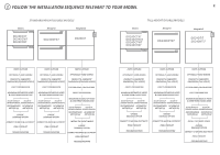
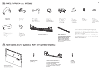
THE INSTALLATION SEQUENCE RELEVANT TO YOUR MODEL 2 STANDARD HEIGHT DOUBLE MODELS Classic Designer Integrated DD24DCX7 DD24DCW7 DD24DCB7 DD24DDFX7 DD24DI7 Classic TALL HEIGHT DOUBLE MODELS Designer DD24DCTX7 DD24DCHTX7 DD24DCTW7 DD24DCTB7 DD24DDFTX7 Integrated DD24DTI7 DD24DHTI7 PARTS - Fisher and Paykel DD24DCX7 | BOOK INSTL DD24D Ph7 US CA EN (English) - Page 3
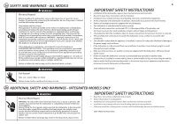
of electric shock. Check with a qualified electrician or service representative if you are in doubt as to whether the appliance is properly grounded. If the dishwasher is installed as a permanently connected appliance: GROUNDING INSTRUCTIONS - This appliance must be connected to a grounded metal - Fisher and Paykel DD24DCX7 | BOOK INSTL DD24D Ph7 US CA EN (English) - Page 4
ADDITIONAL PARTS SUPPLIED WITH INTEGRATED MODELS If the Drain hoses supplied are not long enough to reach your services, you must use a Drain Hose Extension Kit P/N 525798 which will extend the drain hoses by 11' 10" (3.6m). The kit is available from the nearest Fisher & Paykel Authorized Service - Fisher and Paykel DD24DCX7 | BOOK INSTL DD24D Ph7 US CA EN (English) - Page 5
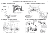
4 OPTIONALLY HARD WIRING PRIOR TO INSTALLATION 5 4a REMOVE THE LOWER DRAWER 43 4b REMOVE THE ACCESS COVER & POWER CORD 4 1 2 41"0(100m0mmm) Access cover To prevent kinked hoses, we recommend rotating the - Fisher and Paykel DD24DCX7 | BOOK INSTL DD24D Ph7 US CA EN (English) - Page 6
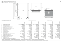
5 PRODUCT DIMENSIONS O KI AN LO Plan DC F Side G B 6 E M J Product dimensions inches (mm) H STANDARD HEIGHT MODELS TALL HEIGHT MODELS Integrated Designer Classic Integrated Designer Classic A overall height1 of product 32 5⁄16 - 34 5⁄8"(820-880)2 32 5⁄16 - 34 5⁄8"(820-880)2 32 5⁄16 - 34 - Fisher and Paykel DD24DCX7 | BOOK INSTL DD24D Ph7 US CA EN (English) - Page 7
6 CABINETRY DIMENSIONS S Side P T 7 Q R Plan Minimum clearances from adjacent cabinetry min. ½" (13 mm) clearance from a corner cupboard min. 1⁄16" (2 mm) clearance to adjacent cupboard door Cabinetry dimensions inches (mm) STANDARD HEIGHT MODELS TALL HEIGHT MODELS Integrated Designer - Fisher and Paykel DD24DCX7 | BOOK INSTL DD24D Ph7 US CA EN (English) - Page 8
7a STANDARD HEIGHT INTEGRATED MODELS ONLY - CUSTOM PANEL CALCULATIONS 8 The following calculations assume the top of the upper panel is aligned with the top of the adjacent cabinetry. The final panel/cabinetry alignment is achieved by adjusting the feet: WIDTH OF ALL PANELS Measure A (the width - Fisher and Paykel DD24DCX7 | BOOK INSTL DD24D Ph7 US CA EN (English) - Page 9
7b TALL HEIGHT INTEGRATED MODELS ONLY - CUSTOM PANEL CALCULATIONS 9 The following calculations assume the top of the upper panel is aligned with the top of the adjacent cabinetry. The final panel/cabinetry alignment is achieved by adjusting the feet: WIDTH OF ALL PANELS Measure A (the width - Fisher and Paykel DD24DCX7 | BOOK INSTL DD24D Ph7 US CA EN (English) - Page 10
11⁄16" (450 mm) ø max. 1½"(38 mm) Services hole Can be located either side of dishwasher, preferably at the bottom of the cavity, as shown. If adequate clearance, services hole can be made higher to clear toekick space. If hole acceptability with your local rabbi in respect to kosher installations. - Fisher and Paykel DD24DCX7 | BOOK INSTL DD24D Ph7 US CA EN (English) - Page 11
9 MAXIMUM DISTANCE OF HOSES & CORD FROM CHASSIS EDGE 11 Left hand side Drain hoses - 78 ½" (2000 mm) Inlet hose - 64 ¾" (1650 mm) Power cord (excl. plug) - 29 ½" (750 mm) Right hand side Drain hoses - 70 ½" (1800 mm) Inlet hose - 49 " (1250 mm) Power cord (excl. plug) - 27 ½" (700 mm) - Fisher and Paykel DD24DCX7 | BOOK INSTL DD24D Ph7 US CA EN (English) - Page 12
12 NOW CHOOSE WHICH INSTALLATION METHOD (a) or (b) IS MORE SUITABLE FOR YOUR CABINETRY... RECOMMENDED METHOD (a) - SECURE WITHOUT DRAWER REMOVAL (FRAMELESS CABINETRY ONLY) 10a ATTACH SIDE MOUNTING BRACKETS Clip all four - Fisher and Paykel DD24DCX7 | BOOK INSTL DD24D Ph7 US CA EN (English) - Page 13
12a SECURE TO THE CABINETRY ON THE SIDES Open the drawer halfway. Using a flat-bladed screwdriver, prize the gray rubber plug out of the trim moulding. 2 Using a small Philips screwdriver, screw through the trim moulding, securing the side mounting bracket to the cabinetry. Do not damage the rubber - Fisher and Paykel DD24DCX7 | BOOK INSTL DD24D Ph7 US CA EN (English) - Page 14
14 - Fisher and Paykel DD24DCX7 | BOOK INSTL DD24D Ph7 US CA EN (English) - Page 15
15 ALTERNATIVE METHOD (b) - SECURE BY DRAWER REMOVAL 10b PULL THROUGH HOSES & PUSH INTO THE CAVITY optionally attach the (x2) two top mounting brackets You can initially level the product 11b REMOVE THE LOWER DRAWER To prevent kinked hoses, we recommend rotating the drawer counter-clockwise and - Fisher and Paykel DD24DCX7 | BOOK INSTL DD24D Ph7 US CA EN (English) - Page 16
12b SECURE TO THE CABINETRY ON THE SIDES For further adjustment, using the most appropriate length Hexagonal socket supplied, fully extend leveling feet up to required distance by hand. To access the side brackets, you might have to push aside the insulation. After securing, ensure the sound - Fisher and Paykel DD24DCX7 | BOOK INSTL DD24D Ph7 US CA EN (English) - Page 17
15b FIT THE SUPPLIED TOEKICK PANEL (OPTIONAL FOR INTEGRATED MODELS) Where the toekick 1 meets the bottom of the tub is the 3 cut-off point Lay the toekick face down on a chopping board or similiar 4 2 Mark this point on the toekick with a pencil 19 Score along with a knife 5 19 Turn the - Fisher and Paykel DD24DCX7 | BOOK INSTL DD24D Ph7 US CA EN (English) - Page 18
INTEGRATED MODELS ONLY - INSTALLING THE FRONT PANELS 18 16 REMOVE BRACKETS FROM PRODUCT WARNING! Electrical Shock Hazard Before continuing, ensure that the product is disconnected from the power supply. - Fisher and Paykel DD24DCX7 | BOOK INSTL DD24D Ph7 US CA EN (English) - Page 19
INTEGRATED MODELS ONLY - INSTALLING THE FRONT PANELS 19 20 ADJUST PANEL HEIGHT TO ALIGN THE CABINETRY GAPS 21 FITTING A CUSTOM TOEKICK PANEL 15⁄86"m(1m6mxm5) x5 + or - 1⁄16" (2 mm) - Fisher and Paykel DD24DCX7 | BOOK INSTL DD24D Ph7 US CA EN (English) - Page 20
. CHOOSE WHICH IS MORE SUITABLE. 20 Dishwasher and Standpipe Ø 1½" (38 mm) Dishwasher using Air Break with Drain Hose Joiner Dishwasher using sink trap with drain hose joiner If space is limited for fixing, push hose through drain hose support to required height 2 2 Supplied drain hose - Fisher and Paykel DD24DCX7 | BOOK INSTL DD24D Ph7 US CA EN (English) - Page 21
from closing properly eg sound insulation, hoses or drawer latches. If a problem occurs, consult the 'Troubleshooting' section of the User guide. If after checking these points you still need assistance, please refer to the Service & Warranty book for warranty details and your nearest Authorized - Fisher and Paykel DD24DCX7 | BOOK INSTL DD24D Ph7 US CA EN (English) - Page 22
- Fisher and Paykel DD24DCX7 | BOOK INSTL DD24D Ph7 US CA EN (English) - Page 23
-
 1
1 -
 2
2 -
 3
3 -
 4
4 -
 5
5 -
 6
6 -
 7
7 -
8
-
9
-
10
-
11
-
12
-
13
-
14
-
15
-
16
-
17
-
18
-
19
-
20
-
21
-
22
-
23
 |
 |
US CA
590204C
03.12
INSTALLATION INSTRUCTIONS
DishDrawer
TM
dishwasher
DD24D 7 & DD24DT 7 models