Fluke 115 Fluke 114,115,117 Manual
Fluke 115 Manual
 |
View all Fluke 115 manuals
Add to My Manuals
Save this manual to your list of manuals |
Fluke 115 manual content summary:
- Fluke 115 | Fluke 114,115,117 Manual - Page 1
® 114, 115, and 117 True-rms Multimeters Users Manual PN 2572573 July 2006, Rev. 1, 2/07 © 2006, 2007 Fluke Corporation, All rights reserved. Printed in China All product names are trademarks of their respective companies. - Fluke 115 | Fluke 114,115,117 Manual - Page 2
. This warranty does not cover fuses, disposable batteries, or damage from accident, neglect, misuse, alteration, contamination, or abnormal conditions of operation or handling. Resellers are not authorized to extend any other warranty on Fluke's behalf. To obtain service during the warranty period - Fluke 115 | Fluke 114,115,117 Manual - Page 3
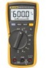
True-rms Multimeters Introduction The Fluke Model 114, Model 115, and Model 117 are battery-powered, true-rms multimeters (hereafter "the Meter") with a 6000-count display and a bar graph. This manual applies to all three models. All figures show the Model 117. These meters meet CAT III IEC 61010-1 - Fluke 115 | Fluke 114,115,117 Manual - Page 4
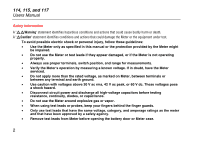
. • Do not use the Meter or test leads if they appear damaged, or if the Meter is not operating properly. • Always use proper terminals, switch position, and range for measurements. • Verify the Meter's operation by measuring a known voltage. If in doubt, have the Meter serviced. • Do not apply more - Fluke 115 | Fluke 114,115,117 Manual - Page 5
True-rms Multimeters Safety Information • Comply with local and national safety requirements when working in hazardous locations. • Use proper protective equipment, as required by local or national authorities when working in hazardous areas. • Avoid working alone. • Use only the replacement fuse - Fluke 115 | Fluke 114,115,117 Manual - Page 6
114, 115, and 117 Users Manual Display No. A B C D E 4 Symbol w s R O Y 6 5 4 3 2 1 16 15 VoltAlert 7 14 17 8 9 10 11 12 13 18 Meaning The Meter is in the VoltAlert™ non-contact voltage detect mode. The Meter function is set to Continuity. The Meter function is set to Diode Test Input is a - Fluke 115 | Fluke 114,115,117 Manual - Page 7
the range for best resolution. 114, 115, & 117 Manual Manual ranging. User sets the Meter's range. 114, 115, & 117 P + Bar graph polarity 114, 115, & 117 Q 0L W The input is too large for the selected range. 114, 115, & 117 R LEAd W Test lead alert. Briefly displayed whenever the - Fluke 115 | Fluke 114,115,117 Manual - Page 8
and testing diodes. edy01f.eps Model 115 & 117 114, 115, & 117 114, 115, & 117 bAtt CAL Err EEPr Err F11 Err Error Messages Battery must be replaced before the Meter will operate. Calibration required. Meter calibration is required before the Meter will operate. Internal error. The Meter must - Fluke 115 | Fluke 114,115,117 Manual - Page 9
True-rms Multimeters and turns off at >250 Ω. 114, 115 & 117 114, 115 & 117 R S j Hz (button) I w Diode Test. Displays OL above 2.0 V. Farads from 1 nF 117 115 & 117 115 & 117 115 & 117 117 Note: All ac functions and Auto-V LoZ are true-rms. AC voltage is ac-coupled. Auto-V LoZ, AC mV and AC amps - Fluke 115 | Fluke 114,115,117 Manual - Page 10
114, 115, and 117 Users Manual Battery Saver ("Sleep Mode") The Meter automatically enters "Sleep mode" and blanks the display if there is no function change, range change, or button press for 20 minutes. Pressing any button or turning the rotary switch awakens the Meter. To disable the Sleep mode, - Fluke 115 | Fluke 114,115,117 Manual - Page 11
turning the Meter on. Power-Up Options are canceled when you turn the Meter off and when sleep mode is activated. True-rms Multimeters Power-Up test leads to the circuit or device, connect the common (COM) test lead before connecting the live lead; when removing the test leads, remove the live lead - Fluke 115 | Fluke 114,115,117 Manual - Page 12
114, 115, and 117 Users Manual Measuring Resistance Testing for Continuity XWWarning edy04f.eps To avoid electric shock, injury, or damage to the Meter, disconnect circuit power and discharge all highvoltage capacitors before testing resistance, continuity, diodes, or capacitance. 10 edy06f. - Fluke 115 | Fluke 114,115,117 Manual - Page 13
Volts AC Volts DC V True-rms Multimeters Making Basic Measurements This function also sets the Meter's input impedance to approximately 3 eps Using Auto Volts Selection (114 & 117 only) With the function switch in the x position, the Meter automatically selects a dc or ac voltage measurement - Fluke 115 | Fluke 114,115,117 Manual - Page 14
and 117 Users Manual Measuring AC or DC Current (115 & 117) XWWarning To avoid personal injury or damage to the Meter: • Never attempt to make an in-circuit current measurement when the opencircuit potential to earth is >600 V. • Check the Meter's fuse before testing. (See "Testing the Fuse") • Use - Fluke 115 | Fluke 114,115,117 Manual - Page 15
of the Meter. Make sure the Meter has the correct function selected, AC or DC, for your current probe. Refer to a Fluke catalog or contact your local Fluke representative for compatible current clamps. True-rms Multimeters Making Basic Measurements Measuring Capacitance (115 & 117 only) edy14f - Fluke 115 | Fluke 114,115,117 Manual - Page 16
114, 115, and 117 Users Manual Measuring Frequency (115 & 117 only) XWWarning To avoid electrical shock, disregard the lower ranges using manual ranging for a stable reading. Detecting AC Voltage Presence (117 only) VoltAlert Hot Neutral VoltAlert RANGE Lo edy09f.eps The Meter measures the - Fluke 115 | Fluke 114,115,117 Manual - Page 17
rely on the VoltAlert detector with shielded wire. Operation may be effected by differences in socket design, insulation thickness and type. saved when the Meter is turned off or goes into sleep mode. True-rms Multimeters Making Basic Measurements Testing Diodes (115 & 117) Good Diode - Fluke 115 | Fluke 114,115,117 Manual - Page 18
114, 115, and 117 Users Manual Using the Bargraph The bar graph is like the needle on an analog meter. It has an overload indicator (>) to the right and a polarity indicator (+)to the left. Because the bar graph is much faster than the digital display, the bar graph is useful for making peak and - Fluke 115 | Fluke 114,115,117 Manual - Page 19
Maintenance of the Meter consists of battery and fuse replacement, as well as case cleaning. Replacing the Battery and Fuse XWWarning To avoid shock, injury, or damage to the Meter: • Remove test leads from the Meter before opening the case or battery door. • Use ONLY a fuse with the amperage - Fluke 115 | Fluke 114,115,117 Manual - Page 20
114, 115, and 117 Users Manual To open the case for fuse replacement: 1. Remove the test leads from the Meter 2. Remove the Meter from its holster. 3. Remove two screws from the case bottom. 4. Separate the case bottom from the case top. 5. Remove the fuse from its holder and replace it with an 11 - Fluke 115 | Fluke 114,115,117 Manual - Page 21
True-rms Multimeters General Specifications General Specifications Accuracy is specified for 1 year after calibration, at operating temperatures of 18 °C to 28 °C, with relative humidity at 0 % to 90 %. Extended specifications are available at www.Fluke.com. Maximum voltage between any terminal and - Fluke 115 | Fluke 114,115,117 Manual - Page 22
and 117 Users Manual Certifications UL, P, CSA, TÜV, ; (N10140), VDE IP Rating (dust and water protection IP42 Table 1. Accuracy Specifications Function DC millivolts DC Volts Range 600.0 mV 6.000 V 60.00 V 600.0 V Auto-V LoZ[1] True-rms 600.0 V AC millivolts[1] Truerms AC Volts[1] True-rms - Fluke 115 | Fluke 114,115,117 Manual - Page 23
test Capacitance Lo-Z Capacitance (Power-up option) True-rms Multimeters General Specifications Table 1 Accuracy Specifications + 2 1.9 % + 2 1.9 % + 2 100 μF - 1000 μF: 1.9 % + 2 > 1000 μF: 5 % + 20 1 nF to 500 μF 10% + 2 typical Model 114, 115, 117 114, 115, 117 115, 117 115, 117 115, 117 21 - Fluke 115 | Fluke 114,115,117 Manual - Page 24
not specified, it is normal for this and other true-rms meters to display nonzero readings when the test leads are disconnected from a circuit or are shorted together. For volts, crest factor of ≤3 at 4000 counts, decreasing linearly to 1.5 at full scale. For amps, crest factor of ≤3. AC volts is ac - Fluke 115 | Fluke 114,115,117 Manual - Page 25
True-rms Multimeters General Specifications Function Volts AC Volts DC Auto-V LoZ Ohms Diode Test Table 2. Input Characteristics Input Impedance or 60 Hz ~3 kΩ 60 dB at dc, 50 or 60 Hz Open Circuit Test Voltage - Fluke 115 | Fluke 114,115,117 Manual - Page 26
114, 115, and 117 Users Manual 24
-
 1
1 -
 2
2 -
 3
3 -
 4
4 -
 5
5 -
 6
6 -
 7
7 -
8
-
9
-
10
-
11
-
12
-
13
-
14
-
15
-
16
-
17
-
18
-
19
-
20
-
21
-
22
-
23
-
24
-
25
-
26
 |
 |

®
PN 2572573
July 2006, Rev. 1, 2/07
© 2006, 2007 Fluke Corporation, All rights reserved. Printed in China
All product names are trademarks of their respective companies.
114, 115, and 117
True-rms Multimeters
Users Manual